Harley Davidson 1986-2003 XL/XLH Sportster. Service Manual - page 10
TROUBLESHOOTING
69
2
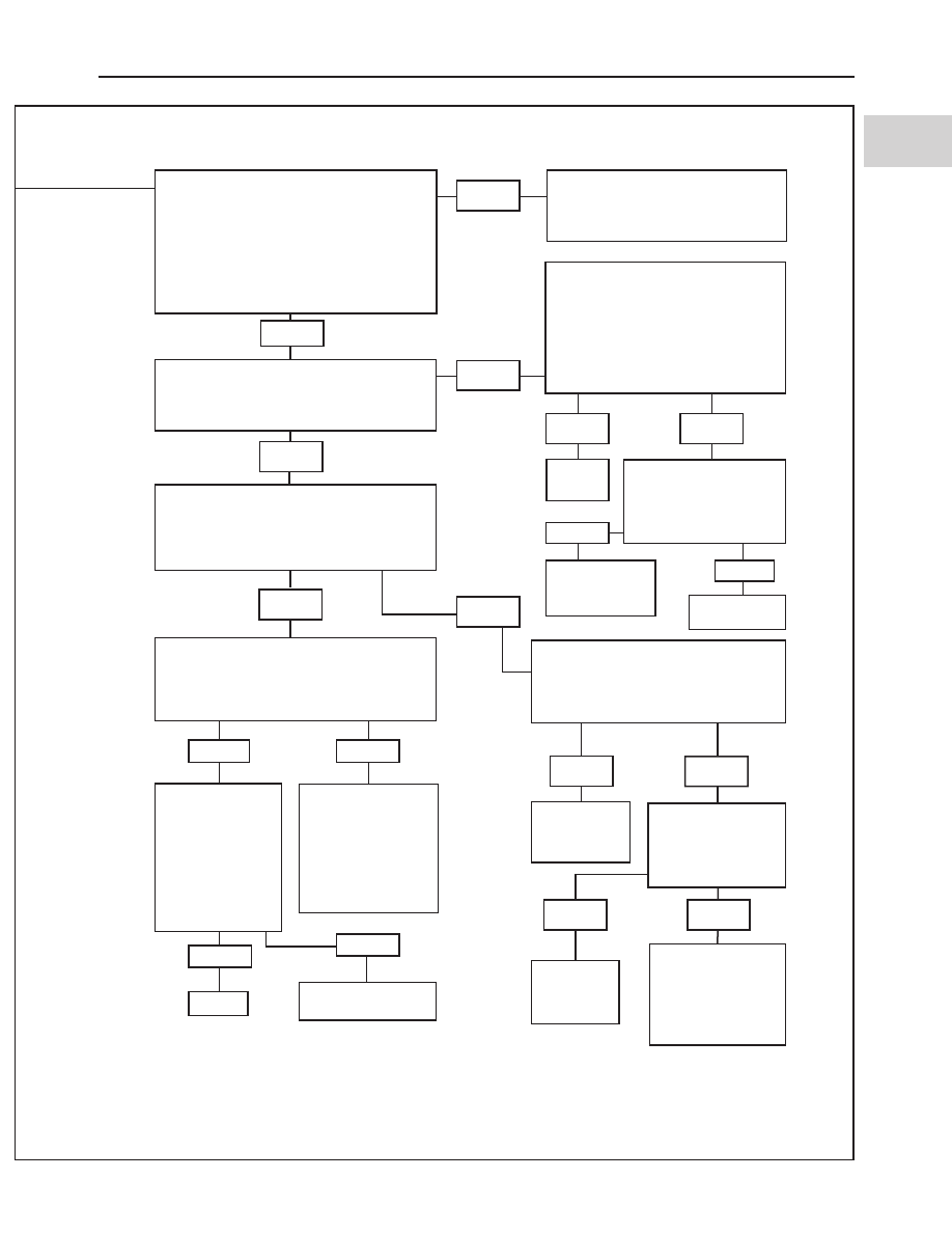
Connect both test harnesses (Figure 44) be-
tween the ignition module and the module
connectors. Check the continuity between
Terminal A in the ignition coil connector
[83B] and Pin 7 on the black test harness.
Measure the resistance between Terminal C
in the ignition coil connector and Pin 6 in the
black test harness. Is the resistance less
than 1.0 ohm?
Poor connection at the ignition mod-
ule connector [10B] or an open in the
harness between the coil and ignition
module. Repair open.
Yes
Disconnect the cam position sensor connec-
tor [14]. With the ignition on, measure volt-
age between terminal A and terminal C of
connector [14B]. Is 5VDC present?
Yes
Reconnect the cam position sensor [14] con-
nector. Turn the ignition on, and measure the
voltage between Pins 3 and 8 on the gray
test harness while cranking the engine. Is
the voltage 0-5 volts?
Yes
No
Remove the test harnesses. Reconnect both
ignition module connectors to the ignition
module and reconnect the cam position sen-
sor connector to the sensor. Try to start the
engine. Does it start?
The crankshaft and
camshaft may be out
of time. Check for
proper cam timing,
pinion gear key fail-
ure, loose rotor cup
or other mechanical
failure.
Replace the cam po-
sition sensor.
Repair.
Turn the ignition off. Measure the resis-
tance between Terminal A in the cam
position sensor connector [14B] and
Pin 1 in the gray test harness. Measure
the resistance between Terminal C in
the cam position sensor connector and
Pin 8 on the gray test harness. Is the re-
sistance greater than 1.0 ohm?
Repair short to
ground the on
red/white wire.
Repair the
open in the
connection.
Remove the cam
timing cover and
crank the engine.
Does the rotor cup
rotate?
Replace the
cam posi-
tion sensor.
Mechanical failure
indicated. Inspect
for a loose rotator
cup and sheared
pinion gear key
(Chapter Five).
Yes
Yes
No
No
No
Yes
Repair
open.
Yes
No
No
Check continuity between
terminal A in the cam po-
sition sensor connector
[14B] and ground. Is con-
tinuity present?
*Replace igni-
tion module.
No
Yes
No
No
Yes
Disconnect the cam position sensor
connector [14]. Measure the resistance
between terminal B on the connector
and Pin 3 in the gray test harness. Is the
resistance greater than 1.0 ohm?
With the engine
running, wiggle
the cam position
sensor and wires
to identify any
loose connections
(engine misfires or
stalls). Were any
found?
*Before replacing the ignition module, confirm it is defective by taking it to a dealership. Further testing
requires the Scanalyzer.