Ford Mondeo (petrol engines). Manual - part 121
 

  Index      Ford     Ford Mondeo - service and repair manual (petrol engines)


Search            


Content   ..  119  120  121  122   ..


Ford Mondeo (petrol engines). Manual - part 121


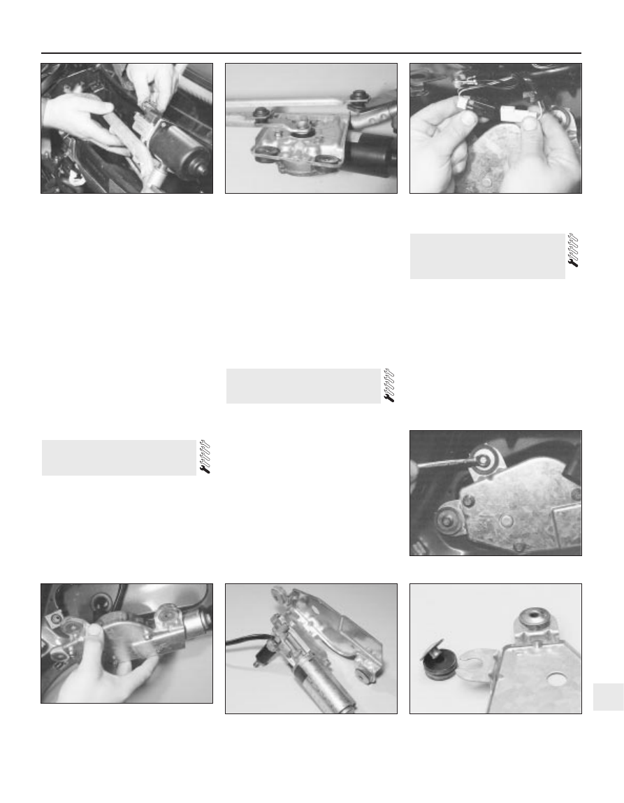
Disconnect the wiper motor multi-plug.
Withdraw the wiper motor, complete with
the linkage, from the bulkhead (see
illustration)
.
10 Mark the position of the motor arm on the
mounting plate, then unscrew the centre nut
(see illustration).
11 Unscrew the motor mounting bolts, and
separate the motor from the linkage assembly.

Refitting

12 Refitting is a reversal of the removal
procedure. There are two tightening torques
for the motor mounting bolts - the lower one
for bolts that are being re-inserted into an old
motor, and the higher ones for bolts that are
being inserted into a new motor. Make sure
that the wiper motor is in its “parked” position
before fitting the motor arm, and check that
the wiper linkage is in line with the motor arm.

Removal

Disconnect the battery negative (earth) lead
(refer to Chapter 5, Section 1).
Remove the tailgate wiper arm as
described in Section 15.
Remove the tailgate inner trim panel by
unscrewing the retaining screws.
Release the multi-plug from the clip, then
disconnect it (see illustration).

Disconnect the wiper motor earth lead.
Unscrew the mounting bolts, and remove
the wiper motor from inside the tailgate (see
illustrations)
.
Unbolt and remove the mounting plate. If
necessary, remove the mounting rubbers for
renewal (see illustrations).

Refitting

Refitting is a reversal of the removal
procedure. Make sure that the wiper motor is
in its “parked” position before fitting the wiper
arm.

Removal

Disconnect the battery negative (earth) lead
(refer to Chapter 5, Section 1).
Using a small screwdriver, prise the trip
computer module out of the facia. To prevent
damage to the facia, place a cloth pad
beneath the screwdriver.
Disconnect the multi-plug from the rear of
the trip computer module, and withdraw the
unit.
If necessary, the bulb can be removed by
twisting it anti-clockwise.

Refitting

Refitting is a reversal of the removal
procedure.

Some models are fitted with an auxiliary
warning system, which monitors brake lights,
sidelights, dipped beam and tail lights,
external temperature, and door/tailgate/
bootlid opening. An engine oil level warning
light on the instrument panel is also part of the
system.
The auxiliary warning system module and
graphic warning display are combined into
one unit.

Service interval reminder

The system also includes a service interval
reminder warning light, which is illuminated if

19 Auxiliary warning system -

general information and
component renewal

18 Trip computer module -

removal and refitting

17 Tailgate wiper motor 

assembly - removal and refitting

Body electrical system  12•17

12

17.6B  . . . and remove the tailgate wiper

motor assembly (Hatchback shown -

Estate similar)

17.7A  Tailgate wiper motor assembly and

mounting plate

17.7B  A mounting rubber removed from

the mounting plate

17.6A  Unscrew the mounting bolts . . .

16.9  Removing the wiper motor and

linkage

16.10  Wiper motor arm and mounting

plate located on the motor

17.4  Disconnecting the tailgate wiper

motor multi-plug

the specified mileage (or time) since the last
service has been reached.
To reset the service interval system and
turn off the light, a switch inside the glovebox
must be depressed for a minimum of 4
seconds with the ignition switched on. This
should be carried out by a Ford dealer if the
vehicle is still in the warranty period.

Component renewal

The following paragraphs describe brief
removal procedures for the auxiliary warning
system components. Disconnect the battery
negative (earth) lead before commencing
work (refer to Chapter 5, Section 1). Refitting
procedures are a reversal of removal.

Display warning bulb

Remove the control assembly.
Prise off the cover, and pull out the relevant
bulb and bulbholder.

Low air temperature warning sender
unit

Remove the front bumper.
Unclip the sender unit and disconnect the
multi-plug (see illustration).

Engine oil level sensor

10 Apply the handbrake, jack up the front of
the vehicle and support it on axle stands.
11 Place a container beneath the oil level
sensor, to catch any spilt oil.

12 Unscrew the screws and remove the
cover from the sensor.
13 Disconnect the multi-plug.
14 Unscrew and remove the sensor, and
remove the seal (see illustration).

Door ajar sensor

15 Remove the door lock as described in
Chapter 11, Section 14.
16 Unclip the sensor and disconnect the
multi-plug.

Low coolant warning switch

17 Refer to Chapter 3, Section 6.

Low washer fluid switch

18 Disconnect the multi-plug from the
washer fluid reservoir.
19 Drain or syphon out the fluid from the
reservoir.
20 Using a screwdriver, lever out the switch
from the reservoir (see illustration).

Service indicator reset switch

21 Remove the glove compartment lid as
described in Chapter 11, Section 32.
22 Carefully lever out the switch using a
small screwdriver.
23 Remove the rear cover and disconnect
the wiring (see illustration).

Control assembly

24 Remove the instrument panel surround,
referring to Section 10.

25 Unscrew the mounting screws,
disconnect the multi-plugs and remove the
assembly.

Bulb failure module

26 Remove the lower facia panel from under
the steering wheel.
27 Unclip the bulb failure module and
disconnect the multi-plug.

Note:  From November 1993, for added
security, a complex Bosch immobiliser system
was fitted to some models. For further details,
refer to your Ford dealer
.
All UK models are fitted with an anti-theft
alarm system, incorporating movement
sensors and an ignition immobiliser. The
system is activated when the vehicle is
locked.
The system includes a start inhibitor circuit,
which makes it impossible to start the engine
with the system armed.
The movement sensors consist of two
ultrasonic units, located in the “B” pillars,
incorporating transmitters and receivers (see
illustrations)
. The receivers check that the
echo frequency matches the original
frequency. If there is any significant
difference, the system triggers the alarm.

20 Anti-theft alarm system - general

information

12•18 Body electrical system

19.9  Low air temperature sender unit

removal

1  Clip     2  Sender unit     3  Multi-plug

19.14  Engine oil level sensor removal

1  Cover    2  Multi-plug    3  Sensor    4  Seal

19.20  Removing the low washer fluid

switch

19.23  Service indicator switch removal

1  Lever out the switch    2  Cover    3  Wiring

20.3A  Disconnecting a movement sensor

multi-plug

20.3B  Removing a movement sensor

The system module is located on a bracket
beneath the right-hand side of the facia. The
set and reset switches are located in a
housing by the lock barrel holder in the doors,
tailgate or bootlid.
To allow temporary opening of the tailgate
or bootlid, an inhibit switch is fitted to the lock
barrel. This suppresses the alarm system until
the tailgate or bootlid is closed again.
Where remote central locking is fitted, an
infra-red receiver is located on the exterior
door handle (see illustration). Note that
excessive heat can destroy this receiver;
therefore, it should be covered with aluminium
tape if (for instance) a paint-drying heat
process is to be used.
The alarm system is fitted with its own horn.
On Hatchback and Saloon models, it is
located on the left-hand side of the luggage
compartment; on Estate models, it is located
on the right-hand side of the luggage
compartment 

(see illustration).

The alarm system incorporates a self-test
function, which can be activated by operating
the bonnet switch or one of the lock position
switches eight times within 10 seconds.
During the check, the horn or buzzer issues
acoustic signals which should occur every
time a door, bonnet or tailgate is opened. If
the doors are double-locked, the signal will
occur when something is moved within the
passenger compartment. A more
comprehensive test can be made using the
Ford FDS 2000 diagnostic tester.
The door lock switches associated with the
alarm system are located behind the door trim
panels (see illustration).

Cruise control is available as an option on
some models.
The cruise control system components are
shown in the accompanying illustration (see
illustration)
. The system is active at road
speeds between 25 mph and 125 mph.
The system comprises an electronic speed
control unit with integral actuator and

21 Cruise control system -

general information

Body electrical system  12•19

12

21.2  Cruise control component location on left-hand drive models

1  Speed control unit
2  Vehicle speed sensor (VSS)
3  Throttle valve actuator
4  Interrupt relay (vehicles with traction control 

system only)

5  Stop-light switch, brake and clutch pedal-

operated disable switches

6  Driver’s controls (buttons on steering wheel)

20.6  Infra-red receiver location on the

door handle

1  Receiver   2  Infra-red eye on the door handle

20.7  Alarm system horn location on

Hatchback and Saloon models

20.10  Alarm system door lock switch

removal

1  Clips (arrowed)     2  Multi-plug

switches mounted in the engine compartment
with a control cable connected to the throttle
valve actuator, driver-operated switches,
brake and clutch pedal switches, an indicator
light, and a road speed sensor.
The driver-operated switches are mounted
on the steering wheel, and allow the driver to
control the various functions.
The vehicle speed sensor uses the
speedometer cable drive pinion to generate
pulses which are fed to the speed control unit.
The stop-light switch, brake pedal switch
and (when applicable) clutch pedal switch are
used to disable the cruise control system. The
stop-light switch is activated when the brake
pedal is applied gently, and the brake pedal
switch is activated when the brake pedal is
applied forcibly.
An indicator light on the instrument panel is
illuminated when the system is in operation.
The following paragraphs describe brief
removal procedures for the cruise control
system components. The battery negative
(earth) lead should be disconnected before
commencing work (refer to Chapter 5, Sec-
tion 1). Refitting is a reversal of removal. 

Speed control switch

Remove the steering column upper and
lower shrouds, with reference to Chapter 10.
10 Remove the air bag module as described
in Section 29.

11 Disconnect the multi-plugs, then unscrew
the screws and remove the switch.

Disable switches

12 Remove the lower facia panel from under
the steering column.
13 Disconnect the multi-plugs from the
clutch switch, brake pedal switch and stop-
light switch.
14 To remove the clutch and brake pedal
switches, twist them anti-clockwise. To
remove the stop-light switch, twist it
clockwise 

(see illustration).

15 Refitting is the reverse of removal. To
ensure correct operation of the brake pedal
switches, reset the switch by fully extending
its plunger (see illustration). Depress the
pedal until the distance between it and the
mounting bracket is as shown in Chapter 9,
illustration 25.6. Hold the pedal in this
position, clip the switch securely into position
and gently raise the pedal to the at-rest
position. This will automatically set the
position of the switch.

Speed control actuator

16 Remove the air cleaner as described in
Chapter 4.
17 Disconnect the actuator cable from the
throttle linkage on the throttle housing, by
releasing the inner cable end fitting from the
segment and unclipping the outer cable from
the bracket.
18 Unscrew the actuator mounting bolt, then

slide the actuator out of the mounting pin
holes.
19 Disconnect the multi-plug and remove the
assembly.
20 Depress the actuating cable cap locking
arm, and remove the cap by turning it anti-
clockwise (see illustration).
21 Gently raise the cable retaining lug by a
maximum of 0.5 mm, and push the cable end
out of the slot in the pulley.
22 When refitting, make sure that the cable
end locks into the slot in the pulley.
23 To locate the cable cap onto the actuator
pulley, keep the cable taut and in the pulley
groove, and pull the throttle linkage end of the
cable to draw the cable cap onto the pulley.
24 To refit the cable cap, keep the cable taut
and the pulley still, then refit the cable cap
tabs into the actuator slots; turn the cap
clockwise until the locking arm locates on the
locking stop. Note: Incorrect assembly of the
cable onto the pulley may result in a high idle
speed. Check that the throttle lever is in its
idle position after refitting the actuator.

Removal

Washer reservoir and pump

Unscrew the bolts, and release the clips to
remove the radiator lower cover.
Unscrew the mounting bolts, and pull the
reservoir forwards slightly (see illustration).
For better access, it may be necessary to
remove the front bumper.
Disconnect the multi-plugs for the
windscreen washer pump and fluid level
sensor (see illustration).
Disconnect the hoses from the windscreen
washer pump and (where applicable) from the
headlamp washer pump. Anticipate some loss
of fluid by placing a container beneath the
reservoir.
Withdraw the reservoir from the vehicle.
Pull the level sensor, the windscreen
washer pump, and (where applicable) the

22 Windscreen/tailgate washer

system components -
removal and refitting

12•20 Body electrical system

21.14  Removal of the speed control

disable switches

1  Clutch switch

3  Stop-light switch

2  Brake pedal switch

21.15  Resetting the brake pedal and stop-

light switches

21.20  Removing the actuator cable

locking arm

22.2  Washer reservoir mounting bolts

(arrowed)

22.3  Disconnecting the washer pump and

level sensor multi-plugs


Content   ..  119  120  121  122   ..