Ford Mondeo (petrol engines). Manual - part 120
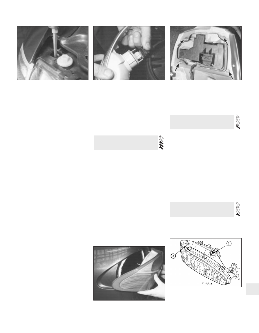
located above the front direction indicator
(see illustration).
11 Withdraw the front direction indicator light
unit.
12 Rotate the bulbholder anti-clockwise, and
withdraw it from the light unit. Alternatively,
the wiring plug can be disconnected from the
bulbholder, leaving the bulb in position (see
illustration). Remove the light unit.
Foglight (front)
13 Unscrew the cross-head screws securing
the front foglight unit to the valance, and
withdraw the light unit from the valance.
14 Prise open the plastic clips, and remove
the rear cover from the light unit.
15 Release the spring clips and withdraw the
bulb, then pull off the wiring connector.
Remove the foglight unit.
Rear light cluster
16 With the tailgate or bootlid open, unhook
the parcel net (where fitted) from the rear of
the luggage compartment.
17 On Saloon and Hatchback models,
remove the screws, release the clips, and
remove the trim panel from the rear cross
panel. On Estate models, it is sufficient to
open the flap.
18 Remove the screws, and press the rear
light trim cover from the guides (where
applicable).
19 Disconnect the wiring multi-plug.
20 Unscrew the four mounting nuts, and
withdraw the light unit from the outside of the
vehicle (see illustrations).
Rear number plate light assembly
21 Remove both number plate lights as
described in Section 5.
22 With the tailgate or bootlid open, remove
the screws and withdraw the inner trim panel.
23 Unscrew the nuts, and remove the outer
cover and number plate base from the
tailgate.
24 Disconnect the multi-plug and remove the
light assembly.
Refitting
25 Refitting of all the external light units is a
reversal of the removal procedure, noting the
following points:
(a) When refitting the rubber seal on the
headlight unit, note that it has a tapered
seat.
(b) If one or both headlights have been
disturbed, have the beam alignment
checked as described in the next Section.
(c) When refitting the rear light cluster, check
the condition of the sealer on the body
panel, and if necessary renew it.
1 Accurate adjustment of the headlight beam
is only possible using optical beam-setting
equipment. This work should therefore be
carried out by a Ford dealer, or other service
station with the necessary facilities.
2 Temporary adjustment can be made after
renewal of a headlight bulb or unit, or as an
emergency measure if the alignment is
incorrect following accident damage. Turn the
adjustment screws on the top of the headlamp
unit to make the adjustment (see illustration).
3 Before making any adjustments to the
settings, it is important that the tyre pressures
are correct, and that the vehicle is standing on
level ground. Bounce the front of the vehicle a
few times to settle the suspension. Ideally,
somebody of average size should sit in the
driver’s seat during the adjustment, and the
vehicle should have a full tank of fuel. Where a
vehicle is fitted with an electrical beam
levelling system, set the switch to the “O”
position before making any adjustments.
4 Whenever temporary adjustments are
made, the settings must be checked and if
necessary reset by a Ford dealer or other
qualified person as soon as possible.
Removal
1 Remove the headlight unit as described in
Section 7, then remove the cover.
2 Disconnect the wiring multi-plug from the
motor.
3 Rotate the motor upwards approximately
60
∞
, then pull it forwards slightly.
4 Disconnect the adjustment spindle by
pressing the ball coupling to one side, away
from the socket on the reflector.
5 Withdraw the motor from the headlight unit.
Refitting
6 Refitting is a reversal of the removal
procedure, but make sure that the motor is
turned down until it engages the stop.
Removal
1 Disconnect the battery negative (earth) lead
(refer to Chapter 5, Section 1).
10 Instrument panel -
removal and refitting
9 Headlight levelling motor -
removal and refitting
8 Headlight beam alignment -
checking and adjustment
Body electrical system 12•13
12
7.20B Removing the rear light cluster unit
8.2 Headlight beam setting adjustment
screws
1 Vertical alignment screw
2 Horizontal alignment screw
7.10 Loosen the front direction indicator
retaining screw
7.12 Disconnecting the wiring plug from
the indicator bulbholder
7.20A Rear light cluster mounting nuts
(arrowed)