Ford Mondeo (petrol engines). Manual - part 118
 

  Index      Ford     Ford Mondeo - service and repair manual (petrol engines)


Search            


Content   ..  116  117  118  119   ..


Ford Mondeo (petrol engines). Manual - part 118


remade, prevent the onset of corrosion in the
future by applying a coat of petroleum jelly or
silicone-based grease, or by spraying on (at
regular intervals) a proprietary ignition sealer
such as Holts Damp Start, or a water-
dispersant lubricant such as Holts Wet Start.

Note: It is important to note that the ignition
switch and the appropriate electrical circuit
must always be switched off before any of the
fuses (or relays) are removed and renewed. In
the event of the fuse/relay unit having to be
removed, the battery earth lead must be
disconnected. When reconnecting the battery,
reference should be made to Chapter 5.
Fuses are designed to break a circuit when
a predetermined current is reached, in order
to protect components and wiring which
could be damaged by excessive current flow.
Any excessive current flow will be due to a
fault in the circuit, usually a short-circuit (see
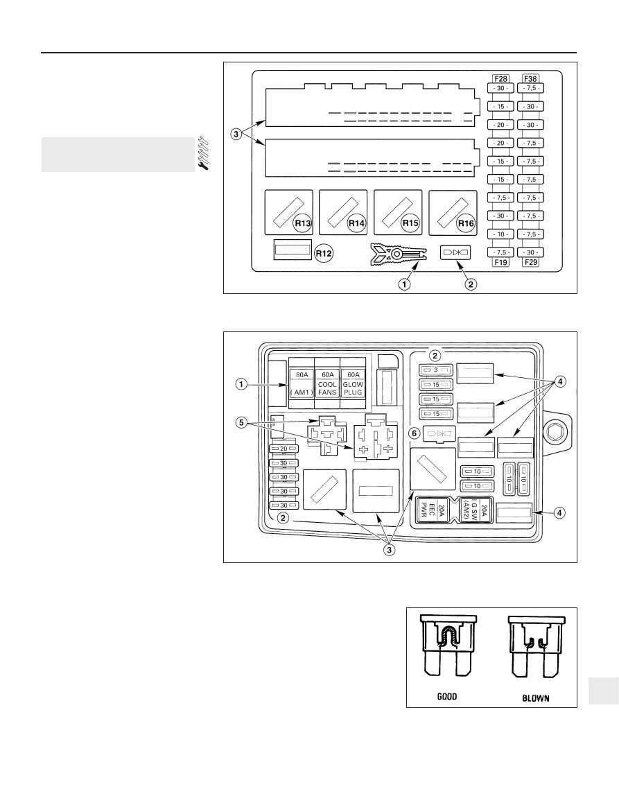
Section 2). The main fusebox, which also
carries some relays, is located inside the
vehicle below the facia panel on the
passenger’s side, and is accessed by a lever
behind the glovebox (see illustration).
A central timer module is located on the
bottom of the main fusebox. This module
contains the time control elements for the
heated rear window, interior lights and
intermittent wiper operation. The module also
activates a warning buzzer/chime when the
vehicle is left with the lights switched on, or if
a vehicle fitted with automatic transmission is
not parked in position “P”.
The auxiliary fusebox is located on the front
left-hand side of the engine compartment,
and is accessed by unclipping and removing
the cover. The auxiliary fusebox also contains
some relays (see illustration). Each circuit is
identified by numbers on the main fusebox
and on the inside of the auxiliary fusebox
cover. Reference to the fuse chart in the
Specifications at the start of this Chapter will
indicate the circuits protected by each fuse.
Plastic tweezers are attached to the main
fusebox and to the inside face of the auxiliary
fuse and block cover, to remove and fit the
fuses and relays.
To remove a fuse, use the tweezers
provided to pull it out of the holder. Slide the
fuse sideways from the tweezers. The wire
within the fuse is clearly visible, and it will be
broken if the fuse is blown (see illustration).
Always renew a fuse with one of an
identical rating. Never substitute a fuse of a
higher rating, or make temporary repairs using
wire or metal foil; more serious damage, or
even fire, could result. The fuse rating is
stamped on top of the fuse. Never renew a
fuse more than once without tracing the
source of the trouble.
Spare fuses of various current ratings are

provided in the cover of the auxiliary fusebox.
Note that if the vehicle is to be laid up for a
long period, fuse 34 in the main fusebox
should be removed, to prevent the ancillary
electrical components from discharging the
battery.
Relays are electrically-operated switches,
which are used in certain circuits. The various
relays can be removed from their respective
locations by carefully pulling them from the
sockets. Each relay in the fuseboxes has a
plastic bar on its upper surface to enable the
use of the tweezers. The locations and

3 Fuses, relays and timer

module - testing and renewal

Body electrical system  12•5

12

3.4  The fuses can be checked visually to

determine if they are blown

3.1  Main fusebox layout

1  Fuse/relay removal tweezers     2  Diode      3  Multi-plug connections

3.3  Auxiliary fusebox layout

1  Fuses 1 to 3

3  Relays R2, R5 and R6

5  Relay sockets for relays R1 and R4

2  Fuses 4 to 8, 11 to 14

4  Relays R7 to R11

6  Diode

functions of the various relays are given in the
Specifications (see illustration).
If a component controlled by a relay
becomes inoperative and the relay is suspect,
listen to the relay as the circuit is operated. If
the relay is functioning, it should be possible
to hear it click as it is energized. If the relay
proves satisfactory, the fault lies with the
components or wiring of the system. If the
relay is not being energized, then either the
relay is not receiving a switching voltage, or
the relay itself is faulty. (Do not overlook the
relay socket terminals when tracing faults.)
Testing is by the substitution of a known good
unit, but be careful; while some relays are
identical in appearance and in operation,
others look similar, but perform different
functions.

The central timer module located on the
bottom of the main fusebox incorporates its
own self-diagnosis function. Note that
diagnosis cannot take place if the heated rear
window is defective.
10 To activate the system, press the heated
rear window button while the ignition is being
switched on, then release the button. Operate
the light switch, washer pump switch and all
of the door switches one after the other, and
check that the buzzer confirms that the input
signals are correct.
11 Now move the wiper lever to the
intermittent wipe position, and check the
output signals by operating the same
switches.
12 The self-diagnosis function is turned off
by switching the ignition off and on again.

Removal

Ignition switch and lock barrel

Disconnect the battery negative (earth) lead
(refer to Chapter 5, Section 1).
Remove the rubber gaiters and locking
rings, then remove the securing screws and
take off the steering column upper and lower
shrouds.
Insert the ignition key, and turn it to the
accessory position. Using a small screwdriver
or twist drill through the hole in the side of the
lock housing, depress the locking plunger and
withdraw the lock barrel (see illustrations).
The switch may be removed from the
steering column assembly by disconnecting
the multi-plug, then using a screwdriver to
release the switch retaining tab (see
illustrations)
.

Windscreen wiper multi-function
switch

Disconnect the battery negative (earth) lead
(refer to Chapter 5, Section 1).
Remove the rubber gaiters and locking
rings, then remove the securing screws and
take off the steering column upper shroud.
Disconnect the multi-plug (see illustration).
Depress the plastic tab with a screwdriver,
and lift the switch assembly from the steering
column (see illustrations).

4 Switches - removal and refitting

12•6 Body electrical system

3.7  “One-touch down” window relay in the

driver’s door

4.3A  Depress the locking plunger . . .

4.3B  . . . and withdraw the ignition lock

barrel

4.7  Disconnecting the multi-plug from the

windscreen wiper multi-function switch

4.8A  Depress the plastic tab with a

screwdriver . . .

4.4A  Release the retaining tab . . .

4.4B  . . . and remove the ignition switch

4.8B  . . . and remove the windscreen wiper

multi-function switch

Main light, auxiliary foglight and rear
foglight combination switch

NoteFrom July 1994 a rvised main light
switch was introduced; this was fitted as
standard in production. If the revised switch is
to be fitted to a pre-July 1994 model, an
adapter lead will also be required to prevent
electrical damage ocurring. Refer to your Ford
dealer for further information
Disconnect the battery negative (earth) lead
(refer to Chapter 5, Section 1).
10 Carefully prise the switch panel from the
facia, using a screwdriver against a cloth pad
to prevent damage to the facia (see
illustration)
.
11 Disconnect the multi-plugs and withdraw
the switch panel (see illustration).
12 Unscrew the four mounting screws, and
remove the switch from the panel.
13 Pull off the switch control knob, and
remove the blanking plug and retainer.
14 Depress the plastic tabs, and remove the
front cover and switch.

Instrument light rheostat

15 Disconnect the battery negative (earth)
lead (refer to Chapter 5, Section 1).
16 Carefully prise the light switch panel from
the facia, using a screwdriver against a cloth
pad to prevent damage to the facia.
17 Disconnect the multi-plugs from the rear
of the switch, then remove the screws and
withdraw the instrument light rheostat from
the panel.

Door mirror control switch

18 Disconnect the battery negative (earth)
lead (refer to Chapter 5, Section 1).
19 Carefully prise the switch from the facia,
using a screwdriver against a cloth pad to
prevent damage to the facia.
20 Disconnect the multi-plug and withdraw
the switch.

Direction indicator, dipped beam and
hazard flasher multi-function switch

21 Disconnect the battery negative (earth)
lead (refer to Chapter 5, Section 1).
22 Remove the rubber gaiters and locking
rings, then remove the screws and take off the
steering column upper shroud.

23 Depress the retaining lug and withdraw
the switch assembly, then disconnect the
multi-plug (see illustration).
24 With the switch assembly removed, pull
out the direction indicator relay if required.

Horn switch (steering wheel without
air bag)

Note: When an air bag is fitted, the horn
switch is removed with the air bag unit. Refer
to Section 28.
25 Disconnect the battery negative (earth)
lead (refer to Chapter 5, Section 1).
26 Carefully pull off the padded centre of the
steering wheel which incorporates the horn
switch.
27 Disconnect the wiring and remove the
switch assembly.

Luggage compartment switch

28 Disconnect the battery negative (earth)
lead (refer to Chapter 5, Section 1).
29 With the tailgate/bootlid open, pull the
weatherstrip from the centre of the rear cross
panel.
30 Carefully prise out the trim fasteners from
the bottom corners of the rear trim, then
unscrew the retaining screws and remove the
trim panel.
31 Disconnect the wiring multi-plug, and pull
out the switch.

Electrically-operated window switch
(single)

32 Disconnect the battery negative (earth)
lead (refer to Chapter 5, Section 1).
33 Carefully prise out the switch from the
door inner trim panel, using a cloth pad to
prevent damage to the trim.
34 Disconnect the multi-plug and remove the
switch.

Electrically-operated window switch
(multiple) and isolator

35 Disconnect the battery negative (earth)
lead (refer to Chapter 5, Section 1).
36 Prise the blanking cap from inside the
inner door handle cavity, and remove the
screw.
37 Hold the inner door handle in its open
position, then remove the bezel and withdraw
it over the handle.

38 Depress the retaining lug and remove the
switch assembly, then disconnect the multi-
plug.

Electrically-operated sunroof switch
and traction control switch

39 Disconnect the battery negative (earth)
lead (refer to Chapter 5, Section 1).
40 Carefully prise out the switch with a
screwdriver, using a cloth pad to prevent
damage to the trim.
41 Disconnect the multi-plug and remove the
switch.

Handbrake-on warning switch

42 Disconnect the battery negative (earth)
lead (refer to Chapter 5, Section 1).
43 Remove the centre console as described
in Chapter 11.
44 Disconnect the multi-plug, then remove
the screw and withdraw the switch from the
handbrake lever mounting bracket (see
illustration)
.

“Economy/Sport” mode switch
(automatic transmission models)

45 Disconnect the battery negative (earth)
lead (refer to Chapter 5, Section 1).
46 Select Neutral, then prise out the selector
indicator panel, using a cloth pad to prevent
damage to the surrounding trim.
47 Push the switch out of the panel, and
disconnect the multi-plug.

Body electrical system  12•7

12

4.44  Disconnecting the multi-plug from

the handbrake lever

4.10  Prising out the light switch

4.11  Disconnecting the multi-plugs from

the light switch and rheostat

4.23  Removing the direction indicator,
dipped beam and hazard flasher multi-

function switch. Direction indicator relay

(flasher unit) is attached

Heated windscreen switch and heated
rear window switch

48 Disconnect the battery negative (earth)
lead (refer to Chapter 5, Section 1).
49 Carefully prise out the switch, using a
cloth pad to prevent damage to the trim (see
illustration)
.
50 Disconnect the multi-plug and remove the
switch (see illustration).

Electrically-operated seat switch and
heated seat switch

51 Disconnect the battery negative (earth)
lead (refer to Chapter 5, Section 1).
52 Carefully prise out the switch, using a
cloth pad to prevent damage to the trim.
53 Disconnect the multi-plug and remove the
switch.

Adaptive damping switch

54 Disconnect the battery negative (earth)
lead (refer to Chapter 5, Section 1).
55 Carefully prise out the switch, using a
cloth pad to prevent damage to the trim.
56 Disconnect the multi-plug and remove the
switch.

Courtesy light door switch

57 Open the door, then unscrew the cross-
head screw and carefully pull the switch from
the pillar (see illustrations). Take care not to
force the wire from the switch terminal,
otherwise it will be difficult to retrieve it from
the pillar.
58 Disconnect the wire, and tie it in a loose
knot to prevent it dropping back into the 
pillar.

Refitting

59 Refitting of all switches is a reversal of the
removal procedure.

Note: Ensure that all exterior lights are
switched off before disconnecting the wiring
connectors from any exterior light bulbs. Do
not touch the glass of halogen-type bulbs
(headlights, front foglights) with the fingers; if
the glass is accidentally touched, clean it with
methylated spirit.

Headlight (dipped beam)

Working under the bonnet, depress the
plastic clips and remove the cover from the
rear of the headlight unit (see illustration).
Release the spring clip and withdraw the
bulb, then disconnect the wiring lead (see
illustrations)
.
Fit the new bulb using a reversal of the
removal procedure. Have the headlight beam
alignment checked as described later in this
Chapter.

Headlight (main beam)

Working under the bonnet, depress the
plastic clips and remove the cover from the
rear of the headlight unit.
Turn the bulbholder anti-clockwise, and
remove it from the rear of the headlight unit
(see illustration).

5 Bulbs (exterior lights) -

renewal

12•8 Body electrical system

4.49  Prising out the heated rear window

switch

4.50  Disconnecting the multi-plug from

the heated rear window switch

4.57A  Unscrew the cross-head screw . . .

5.2A  Release the spring clip . . .

5.2B  . . . and withdraw the headlight bulb

4.57B  . . . and pull out the courtesy light

switch

5.1  Removing the cover from the rear of

the headlight

5.5  Removing the headlight (main beam)

bulbholder


Content   ..  116  117  118  119   ..