Ford Mondeo (petrol engines). Manual - part 116
 

  Index      Ford     Ford Mondeo - service and repair manual (petrol engines)


Search            


Content   ..  114  115  116  117   ..


Ford Mondeo (petrol engines). Manual - part 116


the upper hook. Note that, on low-series
models, the bolster is retained with a screw
(see illustrations).
16 Undo the screw, release the clips, and
detach the upper trim.
17 Remove the rear seat belt lower mounting
bolt, then remove the trim, and pass the seat
belt through it.

“C” pillar trim (Estate)

18 Prise off the caps, unscrew the screws,
and remove the upper trim from the “C” pillar
(see illustration).
19 Unscrew the mounting bolt securing the
rear seat belt upper shackle to the “C” pillar.
20 Unclip and remove the trim.

“D” pillar trim (Estate)

21 Remove the three mounting screws, then
unclip the trim from the “D” pillar.

Lower facia panel

22 Remove the steering column top and
bottom shrouds.
23 Unscrew the mounting screws from the
upper corners and above the coin tray
position, and withdraw the lower facia panel
from the facia (see illustrations).

Refitting

24 Refitting is a reversal of the removal
procedure. Where seat belt fastenings have
been disturbed, make sure that they are
tightened to the specified torque.

Removal

Disconnect the battery negative (earth) lead
(Chapter 5, Section 1).
Pull the ashtray from the facia.
Pull off the gear lever (or selector lever)
knob (see illustration).
Using a screwdriver, carefully prise out the
gear lever gaiter/switch panel or selector lever
panel, as applicable. When necessary,
disconnect the wiring multi-plugs (see
illustration)
.
Remove the adaptive damping switch,
when fitted (Chapter 12).

30 Centre console 

removal and refitting

Bodywork and fittings  11•21

11

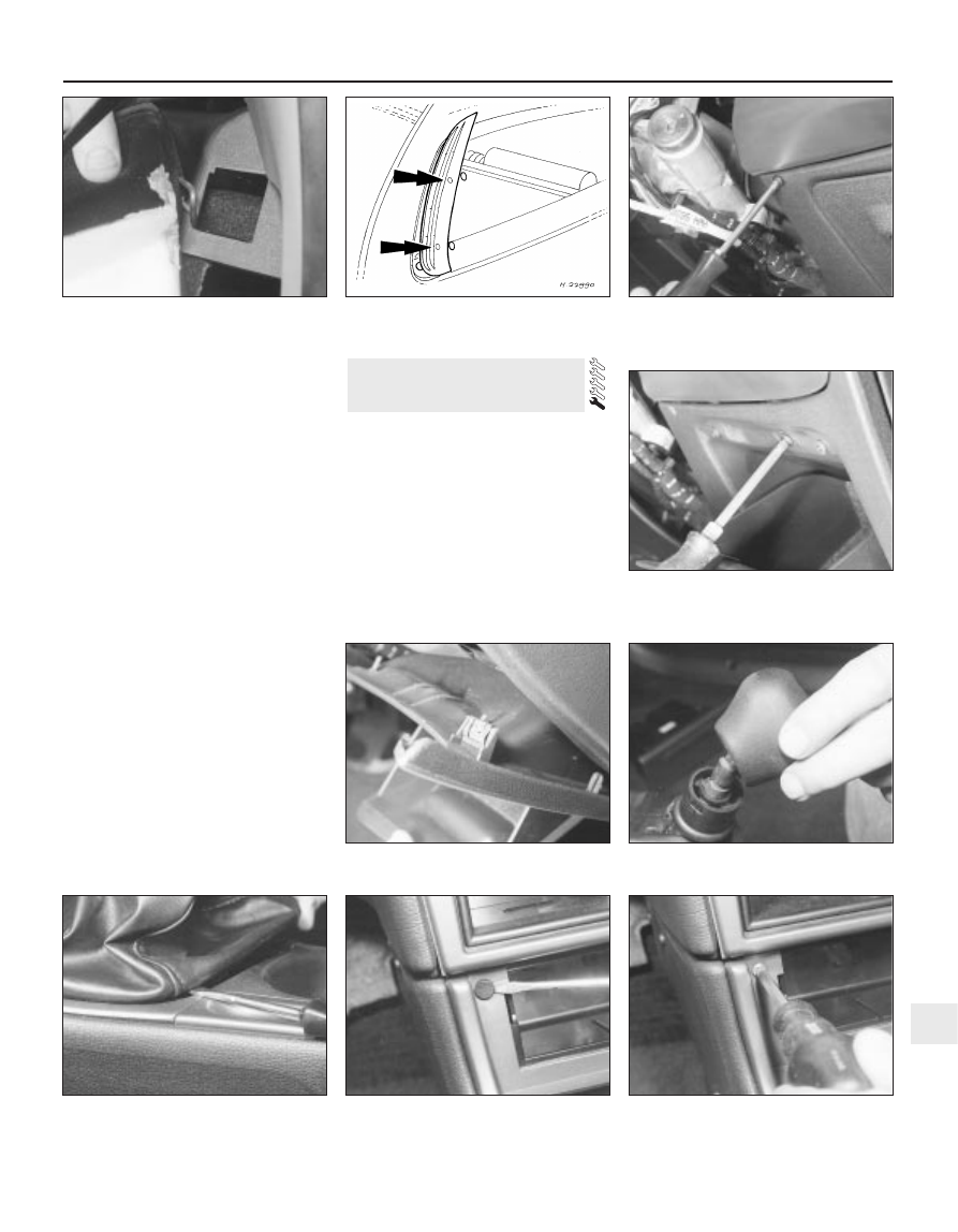
30.4  Prising out the gear lever gaiter

30.6A  Prise off the plastic caps . . .

30.6B  . . . and unscrew the mounting

screws at the front top . . .

29.23B  . . . and above the coin tray

position . . .

29.23C  . . . and withdraw the lower facia

panel

30.3  Gear lever knob removal

29.15B  . . . and release the upper hook

29.18  Screw locations (arrowed) for the

“C” pillar upper trim - Estate models

29.23A  Unscrew the mounting screws

from the upper corners . . .

Prise off the plastic caps, then unscrew the
centre console mounting screws. These are
located on each side, on the front top, and
inside the cassette storage box. The screws
with the washers go on the side of the
console; the front screws are smaller than the
others, and black in colour (see illustrations).
Fully apply the handbrake lever. Withdraw
the centre console, at the same time passing
the gaiter over the handbrake lever (see
illustrations)
.
Disconnect the cigar lighter wiring (see
illustration)
.

Refitting

Refitting is a reversal of the removal
procedure.

Removal

Disconnect the battery negative (earth) lead
(Chapter 5, Section 1).
When applicable, remove the sunroof
switch (Chapter 12).
When applicable, remove the sunroof
handle, after undoing the securing screw (see
illustration)
.
Push the console towards the windscreen,
to disengage it from the clips.

Refitting

Refitting is a reversal of the removal
procedure.

Removal

Open the glovebox. Using a screwdriver,
carefully press in one side of the glovebox
near the hinge, to release it from the plastic
clip (see illustration).
Withdraw the glovebox and, where
necessary, disconnect the wiring multi-plug
for the light.
If necessary, the lock may be removed by
unscrewing the mounting screws and removing
the lock plate and spring (see illustration).
To remove the lock barrel, depress the
spring tabs.

Refitting

Locate the barrel in the lock plate, making
sure that the clips are fully engaged.
Hold the latch pins together, and engage
the right-hand pin of the lock plate.
Refit the spring, and engage the left-hand
pin of the lock plate.
Refit the lock plate, and tighten the screws.
Reconnect the wiring multi-plug and refit
the glovebox, making sure that it is fully
inserted in the plastic clips.

32 Glovebox 

removal and refitting

31 Overhead console 

removal and refitting

11•22 Bodywork and fittings

30.6C  . . . at the sides . . .

30.6D  . . . and inside the cassette storage

box

30.7A  Withdrawing the front of the

console from the facia

31.3  Removing the sunroof handle

securing screw

32.1  Glovebox removal

30.8  Disconnecting the cigar lighter wiring

30.7B  Passing the gaiter over the

handbrake lever

32.3  Glovebox lock mounting screws

(arrowed)

Removal

Disconnect the battery negative (earth) lead
(Chapter 5, Section 1).
Remove the windscreen wiper arms
(Chapter 12), then remove the cowl from just
in front of the windscreen. The cowl is in two
sections, with retaining screws located along
its front edge. With the cowl removed,
disconnect the speedometer cable by pulling
it from the intermediate inner cable extension.
Remove the centre console (Section 30),
then unscrew the screws and remove the
heater side covers (see illustrations).
Remove the steering column (Chapter 10).
Remove the instrument panel (Chapter 12).
Where fitted, unscrew the screws and
remove the automatic warning system
display.
Remove the radio and (if fitted) the CD
player (Chapter 12).
Remove the heater control panel (Chap-
ter 3).
Using a screwdriver, carefully prise out the
headlight switch panel, and disconnect the
wiring multi-plugs.
10 Remove the glovebox (Section 32).
11 Remove the small piece of carpet from
under the passenger side of the facia.
12 Remove the side trim panels from the “A”

and “B” pillars on each side of the vehicle
(Section 29). The upper panels on the “B”
pillars can be left in position.
13 At the base of the right-hand “A” pillar,
disconnect the wiring multi-plugs, earth leads
and aerial, noting their fitted positions.
14 Identify the position of the wiring multi-
plugs on the fusebox, then disconnect them.
15 Disconnect the wiring from the footwell
lights, where fitted.
16 Prise out the speedometer cable rubber
grommet at the bulkhead near the pedal
bracket, then release the cable from the clips.
17 Remove the screws and withdraw the
glovebox side trim, for access to the side
facia mounting screw.
18 Open the front doors. Prise off the trim
covers, then pull away the door weatherstrip
by the side mounting bolt positions on each
side (see illustrations).
19 Unscrew the facia side mounting bolts.
20 Unscrew the facia centre mounting bolts
(see illustrations).
21 Withdraw the facia from the bulkhead, far
enough to be able to reach in behind it.
22 Disconnect the remaining multi-plugs and
connections, noting their locations on the
various components for correct refitting. It will
also be necessary to release some wiring
loom holders, clips and plastic ties, and the
fresh air vent hoses (see illustration).
23 Withdraw the facia from one side of the
vehicle.

33 Facia - removal and refitting

Bodywork and fittings  11•23

11

33.20B  Facia mounting bolt next to the

glovebox

33.20C  Facia centre mounting bolt next to

the heater panel

33.20D  Facia mounting bolt near the

heater

33.3A  Unscrew the screws . . .

33.3B  . . . and remove the heater side

covers

33.18A  Prise off the covers . . .

33.18B  . . . and pull away the weatherstrip

to reveal the facia mounting bolts

33.20A  Facia mounting bolt positions (left-

hand-drive shown, right-hand-drive

similar)

Refitting

24 Refitting is a reversal of the removal
procedure. On completion, check the
operation of all electrical components.

Removal

Front

Apply the handbrake, jack up the front of
the vehicle and support it on axle stands. If

wished, remove the wheel to improve access.
Prise out the stud clip on the front lower
edge of the liner.
Using a Torx key, unscrew the screws
securing the liner to the inner wheel arch
panel (see illustration).
Remove the screws and clips securing the
liner to the outer edge of the wheel arch and
bumper. Withdraw the liner from under the
vehicle (see illustration).

Rear

Chock the front wheels, jack up the rear of
the vehicle and support it on axle stands. If
wished, remove the wheel to improve access.

Unscrew and remove the nuts, located on
either side of the coil spring, securing the
central section of the liner.
Using a Torx key, unscrew the screws
securing the liner to the centre of the inner
wheel arch panel.
Remove the clips securing the liner to the
outer edge of the wheel arch, and withdraw
the liner from under the vehicle.

Refitting

Refitting is a reversal of the removal
procedure. If the wheels were removed,
tighten the wheel nuts to the specified torque.

34 Wheel arch liner 

removal and refitting

11•24 Bodywork and fittings

33.22  Disconnecting the fresh air hoses

34.3  Removing a wheel arch liner retaining

screw

34.4  Removing a front wheel arch liner


Content   ..  114  115  116  117   ..