Ford Mondeo (petrol engines). Manual - part 113
 

  Index      Ford     Ford Mondeo - service and repair manual (petrol engines)


Search            


Content   ..  111  112  113  114   ..


Ford Mondeo (petrol engines). Manual - part 113


Carefully prise off the weatherstrip from the
outside of the door.
Support the glass, then unscrew the bolts
from the support bracket.
Lift the glass from the door while tilting it at
the rear, and withdraw it from the outside.

Front (electric)

Disconnect the battery negative (earth) lead
(Chapter 5, Section 1).
10 Remove the door inner trim panel (Sec-
tion 11).
11 Remove the door exterior mirror (Section 16).
12 Temporarily reconnect the battery and the
window operating switch. Lower the window
until the support bracket and bolts are visible
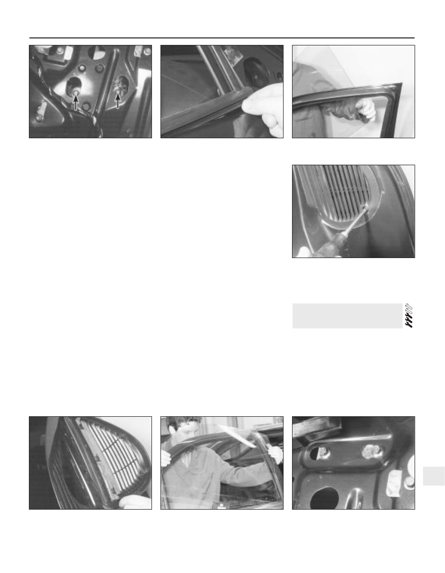
through the holes in the door inner panel (see
illustration)
. Disconnect the battery lead and
the operating switch again.
13 Carefully prise off the weatherstrip from
the outside of the door (see illustration).
14 Support the glass, then unscrew the bolts
from the support bracket.
15 Lift the glass from the door while tilting it
at the rear, and withdraw it from the outside
(see illustration).

Rear (manual/non-electric)

16 Disconnect the battery negative (earth)
lead (Chapter 5, Section 1).
17 Remove the door inner trim panel (Sec-
tion 11).
18 Temporarily refit the regulator handle on
its splines.

19 Lower the window until the glass support
bracket and bolts are visible through the holes
in the door inner panel. Remove the regulator
handle.
20 Support the glass, then unscrew the bolts
from the support bracket.
21 Unscrew the screws, and remove the air
vent grilles from the rear of the rear door (see
illustrations)
.
22 Carefully prise off the weatherstrip from
the outside of the door.
23 Have an assistant raise the glass from the
outside, and hold it near its shut position.
24 Loosen (but do not remove) the three
regulator mounting bolts, then slide the top
bolts to the right, and push them out. Slide the
bottom bolt upwards, and push it out. Lower
the regulator assembly inside the door.
25 Working inside the door, lower the glass
until it is below the regulator position, and
move the glass to the outer side of its
channels.
26 With the help of an assistant, lift the glass
out of the door, and withdraw it from the
outside (see illustration).

Rear (electric)

27 The procedure is as just described for
manual windows, making allowances for the
difference in the regulator mechanism.

Refitting

All doors

28 Refitting is a reversal of the removal

procedure, making sure that the glass is
correctly located in the support bracket.

Removal

Remove the window glass (Section 12).
Loosen (but do not remove) the regulator
and manual winder/electric motor mounting
bolts (see illustrations).
Twist the winder or motor (as applicable) in
the bolt slots, and push it inwards.
Slide the top bolts to the right, and push
them out. Slide the bottom bolt upwards, and
push it out.

13 Door window regulator -

removal and refitting

Bodywork and fittings  11•9

11

12.21B  . . . and remove the air vent grilles

from the rear door

12.26  Lifting the glass from the rear door

13.2A  Window regulator upper mounting

bolts (front door)

12.12  Window support bracket bolts

(arrowed) viewed through the holes in the

door inner panel

12.13  Removing the weatherstrip from the

outside of the door

12.15  Lifting the glass from the front door

12.21A  Unscrew the screws . . .

On electric windows, disconnect the wiring
multi-plug from the motor (see illustration).
Withdraw the window regulator mechanism
from inside the door, through the hole in the
inner panel (see illustrations).

Refitting

Refitting is a reversal of the removal
procedure.

Removal

Front door exterior handle

Remove the door inner trim panel (Sec-
tion 11).
Use a knife to cut through the adhesive
strip, so that the foam insulator can be peeled
back locally for access to the lock. Do not
peel back the foam insulator without first
cutting through the adhesive strip, otherwise
the insulator will be damaged. To ensure a
good seal when the insulator is pressed back,
do not touch the adhesive strip.
Unscrew and remove the two bolts for the
exterior handle outer bezel, and remove the
bezel (see illustrations).

14 Door handle and lock

components 
removal and refitting

11•10 Bodywork and fittings

13.2B  Electric window motor mounting

bolts (front door)

13.2C  Window regulator mounting bolts -

arrowed (rear door)

13.2D  Manual winder mounting bolts (rear

door)

13.5  Disconnecting the wiring multi-plug

from an electrically-operated window

13.6A  Removing the window regulator

mechanism from the front door

13.6B  Front door window regulator

removed from the vehicle

13.6C  Removing the window regulator

mechanism from the rear door

13.6D  Rear door window regulator

removed from the vehicle

14.3A  Remove the two bolts (arrowed) . . .

14.3B  . . . followed by the exterior handle

bezel

Unscrew and remove the lock mounting
bolts on the inner rear edge of the door, and
remove the plate. Also remove the additional
support screw (see illustrations).
Unclip and disconnect the wiring multi-
plugs for the central locking and alarm
systems (see illustration).
Disconnect the wiring multi-plug from the
door lock.
Disconnect the inner handle illumination
light. Undo the screws and remove the inner
handle. Disconnect the operating cable from
the inner handle, as described later in this
Section (see illustrations).
Manipulate the lock and handle assembly
as necessary, and disconnect the wiring
multi-plugs for the alarm sensor and central
locking. Withdraw the complete assembly
from inside the door (see illustrations).
To disconnect the handle assembly from
the lock bracket, slide the rubber posts
inwards, and push out the assembly (see
illustration)
.
10 To remove the handle itself, twist the door
handle through a quarter-turn, and pull out the
connecting rods (see illustration).
11 Remove the alarm sensor and the central
locking “Set-reset” sensor (see illustration).

Rear door exterior handle

12 Remove the door inner trim panel (Sec-
tion 11).
13 Use a knife to cut through the adhesive

Bodywork and fittings  11•11

11

14.8B  Front door lock and exterior handle

assembly removed from the vehicle

14.9  Disconnecting the handle assembly

from the lock bracket

14.10  Pulling out the handle connecting

rods

14.4A  Unscrew the lock mounting 

bolts . . .

14.4B  . . . and remove the plate

14.4C  Removing the additional support

screw

14.5  Disconnecting the central locking

and alarm system wiring multi-plugs

14.7A  Removing the inner handle

14.7B  Disconnecting the operating cable

from the inner handle

14.8A  Removing the lock and exterior

handle assembly from inside the door

strip, so that the foam insulator can be peeled
back for access to the lock. Do not peel back
the foam insulator without first cutting through
the adhesive strip. To ensure a good seal
when the insulator is pressed back, do not
touch the adhesive strip.
14 Prise out the plug from the rear edge of
the door, then unscrew the handle mounting
nuts (see illustrations).
15 Prise up the clip, and disconnect the
operating rod from the lock (see illustration).
16 Withdraw the handle from the outside of
the door (see illustration).

Interior handle

17 Remove the door inner trim panel (Sec-
tion 11).
18 Use a knife to cut through the adhesive
strip, so that the foam insulator can be peeled

back for access to the lock. Do not peel back
the foam insulator without first cutting through
the adhesive strip. To ensure a good seal
when the insulator is pressed back, do not
touch the adhesive strip.
19 Disconnect the interior handle illumination
light.
20 Undo the screws and remove the interior
handle.
21 To remove the cable, first pull back the
plastic outer cable end and blanking piece.
Apply light inward pressure to the control
lever, with the lever in the locked position,
until the inner cable is aligned with the release
slot in the bottom of the cable holder.
22 Push down on the cable ferrule, and
disconnect the inner cable. Remove the
handle assembly.

Lock barrel

23 Remove the exterior handle as described
earlier in this Section.
24 Prise out the barrel retaining tab from the
handle body, using a small screwdriver (see
illustration)
.
25 Insert the key, turn it so that it engages
the barrel, then pull out the barrel (see
illustration)
.

Lock motor - front door

26 Remove the exterior handle as described
earlier in this Section.
27 Extract the clip, and pull out the operating
rod.
28 Remove the operating rod from the plastic
bush, by turning it through a quarter-turn.
29 Release the sensor wiring loom from the
clip.

11•12 Bodywork and fittings

14.11  Removing the central locking “Set-

reset” sensor

14.14A  Prise out the plug . . .

14.14B  . . . and unscrew the handle

mounting nuts

14.25  . . . and pull out the lock barrel

14.31  Unclipping the door-ajar sensor

14.32  Removing the plastic shield from the

locating post

14.15  Disconnect the operating rod from

the lock

14.16  Removing the rear door exterior

handle

14.24  Prise out the barrel retaining tab . . .


Content   ..  111  112  113  114   ..