Ford Mondeo (petrol engines). Manual - part 112
 

  Index      Ford     Ford Mondeo - service and repair manual (petrol engines)


Search            


Content   ..  110  111  112  113   ..


Ford Mondeo (petrol engines). Manual - part 112


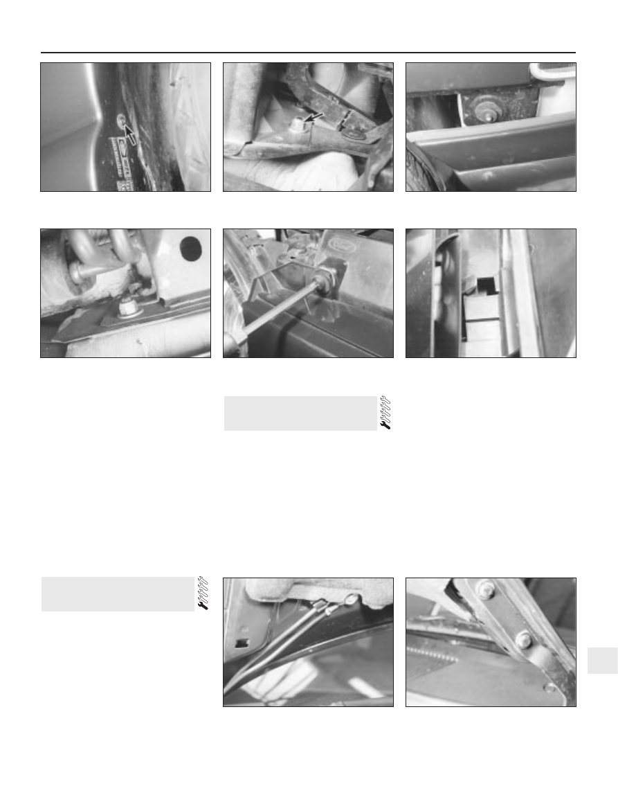
Disconnect the rear exhaust mounting
rubber, and support the exhaust system on an
axle stand.
Remove the screws securing the wheel
arch liners to the rear bumper.
Unscrew the bumper mounting nuts, and
withdraw the bumper rearwards from the
vehicle, at the same time disconnecting the
guides from the side pins (see illustration).

Refitting

Front and rear bumpers

10 Refitting is a reversal of the removal
procedure. Make sure that the guides locate
correctly on the side pins.

Removal

Support the bonnet in the open position.
Using a Torx key, unscrew the radiator grille
mounting screws (see illustration).
Unclip the radiator grille from the front
panel (see illustration).

Refitting

Refitting is a reversal of the removal
procedure.

Removal

Open the bonnet, and support it in the open
position using the stay.
Disconnect the battery negative (earth) lead
(Chapter 5, Section 1).
Prise out the clips from the insulator on the
underside of the bonnet, for access to the
windscreen washer hoses and engine
compartment light. It is not necessary to
completely remove the insulator.
Disconnect the wiring from the engine
compartment light, and unclip the wiring from
the bonnet.

Unbolt the earth lead from the bonnet (see
illustration)
.
Disconnect the windscreen washer hoses
from the bottom of the jets, and unclip the
hose from the bonnet.
To assist in correctly realigning the bonnet
when refitting it, mark the outline of the hinges
with a soft pencil. Loosen the two hinge
retaining bolts on each side (see illustration).
With the help of an assistant, unscrew the
four bolts, release the stay, and lift the bonnet
from the vehicle (see illustration).

Refitting

Refitting is a reversal of the removal
procedure. Position the bonnet hinges within
the outline marks made during removal, but if
necessary alter its position to provide a

8 Bonnet - removal, 

refitting and adjustment

7 Radiator grille 

removal and refitting

Bodywork and fittings  11•5

11

7.3  Unclipping the radiator grille from the

front panel

8.5  Earth lead and washer hoses on the

underside of the bonnet

6.9  Rear bumper mounting nuts

7.2  Removing a radiator grille mounting

screw

8.7  Mark around the bonnet hinges with a

soft pencil before removal

6.4  Screw (arrowed) securing the wheel

arch liner to the front bumper

6.5A  Front bumper mounting bolt

(arrowed)

6.5B  Disconnecting the front bumper from

the side guides

11.3B  . . . and disconnect the multi-plug

uniform gap all round. Adjust the rear height
of the bonnet by repositioning it on the
hinges. Adjust the front height by
repositioning the lock (see Section 10) and
turning the rubber buffers on the engine
compartment front cross panel up or down to
support the bonnet (see illustration).

Removal

With the bonnet open, disconnect the
battery negative (earth) lead (Chapter 5,
Section 1).
Working inside the vehicle, remove the trim
from the “B” pillar, and pull off the door

weatherstrips from the bottom of the door
apertures.
Remove the clips and screws, and
withdraw the lower side trim, to give access to
the bonnet release lever (see illustration).
Release the outer cable from the lever
bracket.
Unscrew and remove the lever mounting
screws, and turn the lever clockwise through
a quarter-turn to disconnect it from the cable.
Remove the radiator grille (Section 7). Also
remove the backing panel from the engine
compartment front crossmember.
Release the inner and outer cables from the
lock.
Withdraw the cable from the engine
compartment, feeding it through the front
crossmember, and removing the grommet
from the bulkhead.

Refitting

Refitting is a reversal of the removal
procedure.

Removal

Remove the radiator grille (Section 7).
Release the inner and outer cables from the
bonnet lock.
Mark the position of the lock on the
crossmember, then unscrew the mounting
nuts and withdraw the lock.

Refitting and adjustment

Refitting is a reversal of the removal
procedure, starting by positioning the lock as
noted before removal.
If the front of the bonnet is not level with the
front wings, the lock may be moved up or
down within the mounting holes. After making
an adjustment, raise or lower the rubber
buffers to support the bonnet correctly.

Removal

Disconnect the battery negative (earth) lead
(Chapter 5, Section 1).
Carefully prise out the plastic cover with a
small screwdriver. Remove the screw, and

11 Door inner trim panel -

removal and refitting

10 Bonnet lock - removal,

refitting and adjustment

9 Bonnet release cable and

lever - removal and refitting

11•6 Bodywork and fittings

8.8  Removing the bonnet

8.9  Buffer for adjustment of the bonnet

front height

9.3  Bonnet release lever

11.2B  . . . remove the screw . . .

11.2A  Prise out the plastic cover . . .

11.2C  . . . and withdraw the bezel from the

inner door handle

11.3A  Remove the window operating

switch . . .

ease the bezel off the inner door handle (see
illustrations)
.
Where applicable, remove the window
operating switch and disconnect the multi-
plug (see illustrations).

Front door

Carefully prise out the cover, remove the
screws and withdraw the door pull handle
(see illustrations).
Prise off the plastic cap, remove the screw,
and withdraw the quarter bezel from the front
of the window opening (see illustrations).

Rear door

Prise off the cap, then remove the screw
and withdraw the door pull handle (see
illustrations)
.

Front and rear doors

On models fitted with manual (ie non-
electric) windows, fully shut the window, and
note the position of the regulator handle.
Release the spring clip by inserting a clean
cloth between the handle and the door trim.
Pull the cloth against the open ends of the clip
to release it, at the same time pulling the
handle from the regulator shaft splines.
Withdraw the handle (and where fitted, the
spacer) and recover the clip (see
illustrations)
.
Prise the caps from the trim panel retaining
screws, then remove the screws and lift off
the panel. Where a speaker is attached to the
trim panel, disconnect the multi-plug (see
illustrations)
.

Bodywork and fittings  11•7

11

11.7B  Withdrawing the window regulator

handle

11.7C  Recover the spring clip from the

window regulator handle

11.8A  Prise out the caps . . .

11.6A  Remove the screw . . .

11.6B  . . . and withdraw the rear door pull

handle

11.7A  Using a clean cloth to release the

spring clip from the window regulator

handle

11.5A  Remove the plastic cap and the

screw . . .

11.5B  . . . then withdraw the quarter bezel

11.4A  Remove the cover . . .

11.4B  . . . then remove the screws and

withdraw the door pull handle

If necessary, the foam insulation may be
removed from the door. First remove the
speaker as described in Chapter 12.
10 On models with manual windows, remove
the foam spacer from the regulator spindle
(see illustration).
11 On the rear door, unscrew the screws and
remove the door pull bracket (see
illustration)
.
12 Carefully cut the adhesive with a knife,
and remove the foam insulation (see
illustration)
.

Refitting

13 Refitting is a reversal of the removal
procedure.

Removal

Front (manual/non-electric)

Disconnect the battery negative (earth) lead
(Chapter 5, Section 1).
Remove the door inner trim panel (Sec-
tion 11).
Remove the door exterior mirror (Sec-
tion 16).
Temporarily refit the regulator handle on its
splines.
Lower the window until the glass support
bracket is visible through the holes in the door
inner panel. Remove the regulator handle.

12 Door window glass 

removal and refitting

11•8 Bodywork and fittings

11.8B  . . . remove the inner-facing 

screws . . .

11.8C  . . . and the side screws . . .

11.8D  . . . then lift off the trim panel

11.10  Removing the foam spacer

11.11  Removing the door pull bracket

from a rear door

11.12  Removing the foam insulation

11.8E  Door trim panel components

1  Door
2  Foam seal
3  Trim panel
4  Top mounting
5  Centre mounting


Content   ..  110  111  112  113   ..