Ford Mondeo (petrol engines). Manual - part 87
 

  Index      Ford     Ford Mondeo - service and repair manual (petrol engines)


Search            


Content   ..  85  86  87  88   ..


Ford Mondeo (petrol engines). Manual - part 87


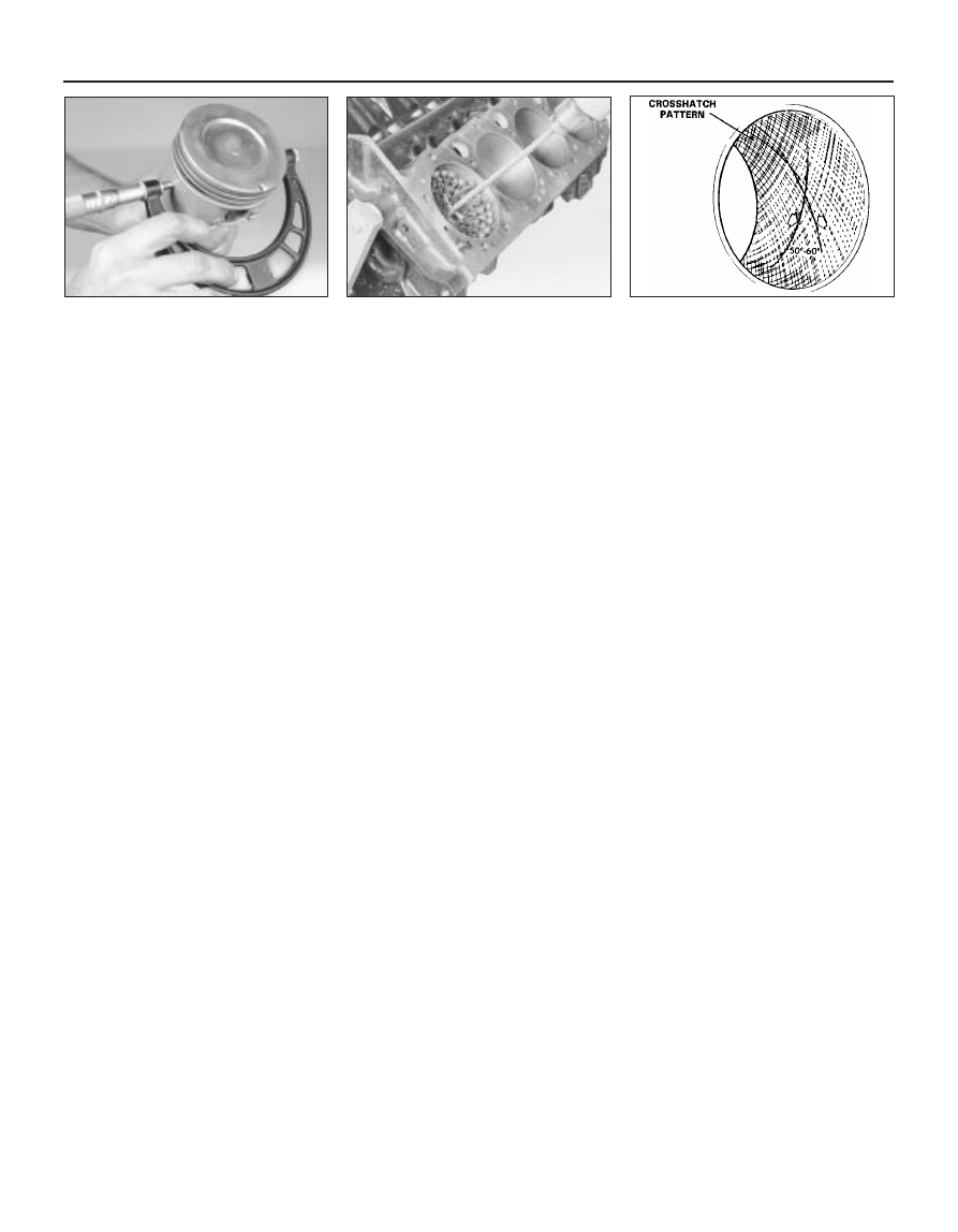
15 Measure the piston diameter at right-
angles to the gudgeon pin axis, just above the
bottom of the skirt; again, note the results
(see illustration).
16 If it is wished to obtain the piston-to-bore
clearance, measure the bore and piston skirt
as described above, and subtract the skirt
diameter from the bore measurement. If the
precision measuring tools shown are not
available, the condition of the pistons and
bores can be assessed, though not quite as
accurately, by using feeler gauges as follows.
Select a feeler gauge of thickness equal to the
specified piston-to-bore clearance, and slip it
into the cylinder along with the matching
piston. The piston must be positioned exactly
as it normally would be. The feeler gauge
must be between the piston and cylinder on
one of the thrust faces (at right-angles to the
gudgeon pin bore). The piston should slip
through the cylinder (with the feeler gauge in
place) with moderate pressure; if it falls
through or slides through easily, the clearance
is excessive, and a new piston will be
required. If the piston binds at the lower end
of the cylinder, and is loose toward the top,
the cylinder is tapered. If tight spots are
encountered as the piston/feeler gauge is
rotated in the cylinder, the cylinder is out-of-
round (oval).
17 Repeat these procedures for the
remaining pistons and cylinder bores.
18 Compare the results with the
Specifications at the beginning of this
Chapter; if any measurement is beyond the
dimensions specified for that class (check the
piston crown marking to establish the class of
piston fitted), or if any bore measurement is
significantly different from the others
(indicating that the bore is tapered or oval),
the piston or bore is excessively-worn.
19 Worn pistons must be renewed; at the
time of writing, pistons are available as Ford
replacement parts only as part of the
complete piston/connecting rod assembly.
See a Ford dealer or engine reconditioning
specialist for advice.
20 If any of the cylinder bores are badly

scuffed or scored, or if they are excessively-
worn, out-of-round or tapered, the usual
course of action would be to have the cylinder
block/crankcase rebored, and to fit new,
oversized, pistons on reassembly. See a Ford
dealer or engine reconditioning specialist for
advice.
21 If the bores are in reasonably good
condition and not excessively-worn, then it
may only be necessary to renew the piston
rings.
22 If this is the case (and if new rings can be
found), the bores should be honed, to allow
the new rings to bed in correctly and provide
the best possible seal; before honing the
bores, refit the main bearing caps (without the
bearing shells), and tighten the bolts to the
specified torque wrench setting. Note: If you
don’t have the tools, or don’t want to tackle
the honing operation, most engine
reconditioning specialists will do it for a
reasonable fee.
23 Two types of cylinder hones are
commonly available - the flex hone or “bottle-
brush” type, and the more traditional
surfacing hone with spring-loaded stones.
Both will do the job and are used with a
power drill, but for the less-experienced
mechanic, the “bottle-brush” hone will
probably be easier to use. You will also need
some paraffin or honing oil, and rags.
Proceed as follows:
(a) Mount the hone in the drill, compress the

stones, and slip it into the first bore (see
illustration)
. Be sure to wear safety
goggles or a face shield!

(b) Lubricate the bore with plenty of honing

oil, switch on the drill, and move the hone
up and down the bore, at a pace that will
produce a fine cross-hatch pattern on the
cylinder walls. Ideally, the cross-hatch
lines should intersect at approximately a
60° angle (see illustration). Be sure to
use plenty of lubricant, and don’t take off
any more material than is absolutely
necessary to produce the desired finish.
Note: Piston ring manufacturers may
specify a different crosshatch angle - read

and follow any manuals included with
the new rings.

(c) Don’t withdraw the hone from the bore

while it’s running. Instead, switch off the
drill, and continue moving the hone up
and down the bore until it comes to a
complete stop, then compress the stones
and withdraw the hone. If you’re using a
“bottle-brush” hone, switch off the drill,
then turn the chuck in the normal
direction of rotation while withdrawing the
hone from the bore.

(d) Wipe the oil out of the bore, and repeat

the procedure for the remaining cylinders.

(e) When all the cylinder bores are honed,

chamfer the top edges of the bores with a
small file, so the rings won’t catch when
the pistons are installed. Be very careful
not to nick the cylinder walls with the end
of the file.

(f)

The entire cylinder block/crankcase must
be washed very thoroughly with warm,
soapy water, to remove all traces of the
abrasive grit produced during the honing
operation. Note: The bores can be
considered clean when a lint-free white
cloth - dampened with clean engine oil -
used to wipe them out doesn’t pick up
any more honing residue, which will show
up as grey areas on the cloth. Be sure to
run a brush through all oil holes and
galleries, and flush them with running
water.

(g) When the cylinder block/crankcase is

completely clean, rinse it thoroughly and
dry it, then lightly oil all exposed
machined surfaces, to prevent rusting.

24 The cylinder block/crankcase should now
be completely clean and dry, with all
components checked for wear or damage,
and repaired or overhauled as necessary.
Refit as many ancillary components as
possible, for safekeeping (see paragraphs 9
and 10 above). If reassembly is not to start
immediately, cover the block with a large
plastic bag to keep it clean, and protect the
machined surfaces as described above to
prevent rusting.

2B•16 Engine removal and general engine overhaul procedures

11.15  Measure the piston skirt diameter at

right-angles to the gudgeon pin axis, just

above the base of the skirt

11.23A  A “bottle-brush” hone will produce

better results if you have never honed

cylinders before

11.23B  The cylinder hone should leave a

smooth, cross-hatch pattern with the lines

intersecting at approximately a 60º angle

Note: Always check first what replacement
parts are available before planning any
overhaul operation; refer to Section 1 of this
Part. A Ford dealer, or a good engine
reconditioning specialist/automotive parts
supplier may be able to suggest alternatives
which will enable you to overcome the lack of
replacement parts.
Before the inspection process can be
carried out, the piston/connecting rod
assemblies must be cleaned, and the original
piston rings removed from the pistons. The
rings should have smooth, polished working
surfaces, with no dull or carbon-coated
sections (showing that the ring is not sealing
correctly against the bore wall, so allowing
combustion gases to blow by) and no traces
of wear on their top and bottom surfaces. The
end gaps should be clear of carbon, but not
polished (indicating a too-small end gap), and
all the rings (including the elements of the oil
control ring) should be free to rotate in their
grooves, but without excessive up-and-down
movement. If the rings appear to be in good
condition, they are probably fit for further use;
check the end gaps (in an unworn part of the
bore) as described in Section 16. If any of the
rings appears to be worn or damaged, or has
an end gap significantly different from the
specified value, the usual course of action is
to renew all of them as a set. Note: While it is
usual always to renew piston rings when an
engine is overhauled, this of course assumes
that rings are available separately - if not, it
follows that great care must be taken not to
break or damage any of the rings during the
following procedures, and to ensure that each
ring is marked on removal so that it is refitted
only the original way up, and only to the same
groove.
Using a piston ring renoval  tool, carefully
remove the rings from the pistons. Be careful
not to nick or gouge the pistons in the
process, and mark or label each ring as it is
removed, so that its original top surface can

be identified on reassembly, and so that it can
be returned to its original groove. Take care
also with your hands - piston rings are sharp! 
Scrape all traces of carbon from the top of
the piston. A hand-held wire brush or a piece
of fine emery cloth can be used, once the
majority of the deposits have been scraped
away. Do not, under any circumstances, use a
wire brush mounted in a drill motor to remove
deposits from the pistons - the piston material
is soft, and may be eroded away by the wire
brush.
Use a piston ring groove-cleaning tool to
remove carbon deposits from the ring
grooves. If a tool isn’t available, but
replacement rings have been found, a piece
broken off the old ring will do the job. Be very
careful to remove only the carbon deposits -
don’t remove any metal, and do not nick or
scratch the sides of the ring grooves (see
illustrations)
. Protect your fingers - piston
rings are sharp!
Once the deposits have been removed,
clean the piston/rod assemblies with solvent,
and dry them with compressed air (if
available). Make sure the oil return holes in the
back sides of the ring grooves, and the oil

hole in the lower end of each rod, are clear.
If the pistons and cylinder walls aren’t
damaged or worn excessively - refer to
Section 11 for details of inspection and
measurement procedures - and if the cylinder
block/crankcase is not rebored, new pistons
won’t be necessary. Normal piston wear
appears as even vertical wear on the piston
thrust surfaces, and slight looseness of the
top ring in its groove.
Carefully inspect each piston for cracks
around the skirt, at the pin bosses, and at the
ring lands (between the ring grooves).
Look for scoring and scuffing on the thrust
faces of the skirt, holes in the piston crown,
and burned areas at the edge of the crown. If
the skirt is scored or scuffed, the engine may
have been suffering from overheating and/or
abnormal combustion, which caused
excessively-high operating temperatures. The
cooling and lubrication systems should be
checked thoroughly. A hole in the piston
crown is an indication that abnormal
combustion (pre-ignition) was occurring.
Burned areas at the edge of the piston crown
are usually evidence of spark knock
(detonation). If any of the above problems
exist, the causes must be corrected, or the
damage will occur again. The causes may
include intake air leaks, incorrect fuel/air
mixture, incorrect ignition timing, or EGR
system malfunctions.
Corrosion of the piston, in the form of small
pits, indicates that coolant is leaking into the
combustion chamber and/or the crankcase.
Again, the cause must be corrected, or the
problem may persist in the rebuilt engine.
10 Check the piston-to-rod clearance by
twisting the piston and rod in opposite
directions. Any noticeable play indicates
excessive wear, which must be corrected. The
piston/connecting rod assemblies should be
taken to a Ford dealer or engine recondition-
ing specialist to have the pistons, gudgeon
pins and rods checked, and new components
fitted as required.
11 Don’t attempt to separate the pistons
from the connecting rods (even if non-genuine
replacements are found elsewhere). This is a
task for a Ford dealer or similar engine
reconditioning specialist, due to the special
heating equipment, press, mandrels and
supports required to do the job. If the
piston/connecting rod assemblies do require
this sort of work, have the connecting rods
checked for bend and twist, since only such
engine repair specialists will have the facilities
for this purpose.
12 Check the connecting rods for cracks and
other damage. Temporarily remove the big-
end bearing caps and the old bearing shells,
wipe clean the rod and cap bearing recesses,
and inspect them for nicks, gouges and
scratches. After checking the rods, replace
the old shells, slip the caps into place, and
tighten the bolts finger-tight.

12 Piston/connecting rod

assemblies - inspection

Engine removal and general engine overhaul procedures  2B•17

2B

12.4A  The piston ring grooves can be

cleaned with a special tool, as shown 

here . . .

12.4B  . . . or a section of a broken ring, if

available

If a piston ring removal tool is not
available, the rings can be removed by
hand, expanding them over the top of
the pistons. The use of two or three old
feeler blades will be helpful in
preventing the rings dropping into
empty grooves.

Note: Always check first what replacement
parts are available before planning any
overhaul operation; refer to Section 1 of this
Part. A Ford dealer, or a good engine
reconditioning specialist/automotive parts
supplier, may be able to suggest alternatives
which will enable you to overcome the lack of
replacement parts.
Clean the crankshaft, and dry it with
compressed air if available. 

Warning: Wear eye protection
when using compressed air! Be
sure to clean the oil holes with a
pipe cleaner or similar probe.

Check the main and crankpin (big-end)
bearing journals for uneven wear, scoring,
pitting and cracking.
Rub a penny across each journal several
times (see illustration). If a journal picks up
copper from the penny, it is too rough.
Remove all burrs from the crankshaft oil
holes with a stone, file or scraper.
Using a micrometer, measure the diameter
of the main bearing and crankpin (big-end)
journals, and compare the results with the
Specifications at the beginning of this Chapter
(see illustration).
By measuring the diameter at a number of
points around each journal’s circumference,
you will be able to determine whether or not
the journal is out-of-round. Take the
measurement at each end of the journal, near
the webs, to determine if the journal is
tapered.
If the crankshaft journals are damaged,
tapered, out-of-round, or worn beyond the
limits specified in this Chapter, the crankshaft
must be taken to an engine overhaul
specialist, who will regrind it, and who can
supply the necessary undersize bearing
shells.
Check the oil seal journals at each end of
the crankshaft for wear and damage. If either
seal has worn an excessive groove in its

journal, consult an engine overhaul specialist,
who will be able to advise whether a repair is
possible, or whether a new crankshaft is
necessary.

Note: Always check first what replacement
parts are available before planning any
overhaul operation; refer to Section 1 of this
Part. A Ford dealer, or a good engine
reconditioning specialist/automotive parts
supplier, may be able to suggest alternatives
which will enable you to overcome the lack of
replacement parts.
Even though the main and big-end bearing
shells should be renewed during the engine
overhaul, the old shells should be retained for
close examination, as they may reveal
valuable information about the condition of
the engine (see illustration).
Bearing failure occurs because of lack of
lubrication, the presence of dirt or other
foreign particles, overloading the engine, and
corrosion. Regardless of the cause of bearing
failure, it must be corrected before the engine
is reassembled, to prevent it from happening
again.
When examining the bearing shells, remove
them from the cylinder block/crankcase and
main bearing caps, and from the connecting
rods and the big-end bearing caps, then lay
them out on a clean surface in the same
general position as their location in the
engine. This will enable you to match any
bearing problems with the corresponding
crankshaft journal. Do not touch any shell’s
bearing surface with your fingers while
checking it, or the delicate surface may be
scratched.
Dirt or other foreign matter gets into the
engine in a variety of ways. It may be left in
the engine during assembly, or it may pass
through filters or the crankcase ventilation
system. It may get into the oil, and from there
into the bearings. Metal chips from machining
operations and normal engine wear are often
present. Abrasives are sometimes left in
engine components after reconditioning,

especially when parts are not thoroughly
cleaned using the proper cleaning methods.
Whatever the source, these foreign objects
often end up embedded in the soft bearing
material, and are easily recognized. Large
particles will not embed in the material, and
will score or gouge the shell and journal. The
best prevention for this cause of bearing
failure is to clean all parts thoroughly, and to
keep everything spotlessly-clean during
engine assembly. Frequent and regular engine
oil and filter changes are also recommended.
Lack of lubrication (or lubrication
breakdown) has a number of inter-related
causes. Excessive heat (which thins the oil),
overloading (which squeezes the oil from the
bearing face) and oil leakage (from excessive
bearing clearances, worn oil pump or high
engine speeds) all contribute to lubrication
breakdown. Blocked oil passages, which
usually are the result of misaligned oil holes in
a bearing shell, will also starve a bearing of oil,
and destroy it. When lack of lubrication is the
cause of bearing failure, the bearing material
is wiped or extruded from the shell’s steel
backing. Temperatures may increase to the
point where the steel backing turns blue from
overheating.
Driving habits can have a definite effect on
bearing life. Full-throttle, low-speed operation
(labouring the engine) puts very high loads on
bearings, which tends to squeeze out the oil
film. These loads cause the shells to flex,
which produces fine cracks in the bearing
face (fatigue failure). Eventually, the bearing
material will loosen in pieces, and tear away
from the steel backing. Short-distance driving
leads to corrosion of bearings, because
insufficient engine heat is produced to drive
off condensed water and corrosive gases.
These products collect in the engine oil,
forming acid and sludge. As the oil is carried

14 Main and big-end bearings -

inspection

13 Crankshaft - inspection

2B•18 Engine removal and general engine overhaul procedures

13.3  Rubbing a penny lengthwise along

each journal will reveal its condition - if

copper rubs off and is embedded in the

crankshaft, the journals should be

reground

13.5  Measure the diameter of each

crankshaft journal at several points, to

detect taper and out-of-round conditions

14.1  When inspecting the main and big-

end bearings, look for these problems

to the engine bearings, the acid attacks and
corrodes the bearing material.
Incorrect shell refitting during engine
assembly will lead to bearing failure as well.
Tight-fitting shells leave insufficient bearing
running clearance, and will result in oil
starvation. Dirt or foreign particles trapped
behind a bearing shell result in high spots on
the bearing, which lead to failure. Do not
touch any shell’s bearing surface with your
fingers during reassembly; there is a risk of
scratching the delicate surface, or of
depositing particles of dirt on it.

Before reassembly begins, ensure that all
new parts have been obtained, and that all
necessary tools are available. Read through
the entire procedure, to familiarise yourself
with the work involved, and to ensure that all
items necessary for reassembly of the engine
are at hand. In addition to all normal tools and
materials, suitable sealant will be required for
two of the joint faces (Ford recommend
Hylosil 102 for the cylinder block/crankcase-
to-sump/oil pump/oil seal carrier joints, and
Loctite 518 for the camshaft right-hand
bearing caps). In all other cases, provided the
relevant mating surfaces are clean and flat,
new gaskets will be sufficient to ensure joints
are oil-tight. Do not use any kind of silicone-
based sealant on any part of the fuel system
or inlet manifold, and never use exhaust
sealants upstream of the catalytic converter.
In order to save time and avoid problems,
engine reassembly can be carried out in the
following order:
(a) Crankshaft (Section 17).
(b) Piston/connecting rod assemblies

(Section 18).

(c) Oil pump (Part A of this Chapter, Section

16).

(d) Sump (Part A of this Chapter, Section 15).
(e) Flywheel/driveplate (Part A of this

Chapter, Section 21).

(f)

Cylinder head (Part A of this Chapter,
Section 14).

(g) Timing belt inner cover, tensioner and

toothed pulleys, and timing belt (Part A of
this Chapter).

(h) Engine external components.
At this stage, all engine components should
be absolutely clean and dry, with all faults
repaired; they should be laid out (or in
individual containers) on a completely-clean
work surface.

Before installing new piston rings, check
the end gaps. Lay out each piston set with a
piston/connecting rod assembly, and keep
them together as a matched set from now on.
Insert the top compression ring into the first
cylinder, and square it up with the cylinder
walls by pushing it in with the top of the piston
(see illustration). The ring should be near the
bottom of the cylinder, at the lower limit of
ring travel.
To measure the end gap, slip feeler gauges
between the ends of the ring, until a gauge
equal to the gap width is found (see
illustration)
. The feeler gauge should slide
between the ring ends with a slight amount of
drag. Compare the measurement to the value
given in the Specifications Section of this
Chapter; if the gap is larger or smaller than
specified, double-check to make sure you
have the correct rings before proceeding. If
you are assessing the condition of used rings,
have the cylinder bores checked and
measured by a Ford dealer or similar engine
reconditioning specialist, so that you can be
sure of exactly which component is worn, and
seek advice as to the best course of action to
take.
If the end gap is still too small, it must be
opened up by careful filing of the ring ends
using a fine file. If it is too large, this is not as
serious, unless the specified limit is exceeded,
in which case very careful checking is
required of the dimensions of all components,
as well as of the new parts.
Repeat the procedure for each ring that will
be installed in the first cylinder, and for each

ring in the remaining cylinders. Remember to
keep rings, pistons and cylinders matched up.
Refit the piston rings as follows. Where the
original rings are being refitted, use the marks
or notes made on removal, to ensure that
each ring is refitted to its original groove and
the same way up. New rings generally have
their top surfaces identified by markings
(often an indication of size, such as “STD”, or
the word “TOP”) - the rings must be fitted with
such markings uppermost (see illustration).
Note: Always follow the manuals printed
on the ring package or box - different
manufacturers may require different
approaches. Do not mix up the top and
second compression rings, as they usually
have different cross-sections.
The oil control ring (lowest one on the
piston) is usually installed first. It is composed
of three separate elements. Slip the
spacer/expander into the groove (see
illustration)
. If an anti-rotation tang is used,
make sure it is inserted into the drilled hole in
the ring groove. Next, install the lower side
rail. Don’t use a piston ring installation tool on
the oil ring side rails, as they may be
damaged. Instead, place one end of the side
rail into the groove between the
spacer/expander and the ring land, hold it
firmly in place, and slide a finger around the
piston while pushing the rail into the groove

16 Piston rings - refitting

15 Engine overhaul 

reassembly sequence

Engine removal and general engine overhaul procedures  2B•19

2B

16.7A  Installing the spacer/expander in

the oil control ring groove

16.2  When checking piston ring end gap,

the ring must be square in the cylinder

bore (this is done by pushing the ring down

with the top of a piston, as shown)

16.3  With the ring square in the bore,

measure the end gap with a feeler 

gauge

16.6  Look for etched markings (“STD” -

indicating a standard-sized ring - shown

here) identifying piston ring top surface


Content   ..  85  86  87  88   ..