Ford Mondeo (petrol engines). Manual - part 86
grinding or head resurfacing. Use
compressed air, if available, to blow out all the
oil holes and passages.
2 Beginning at one end of the head, lubricate
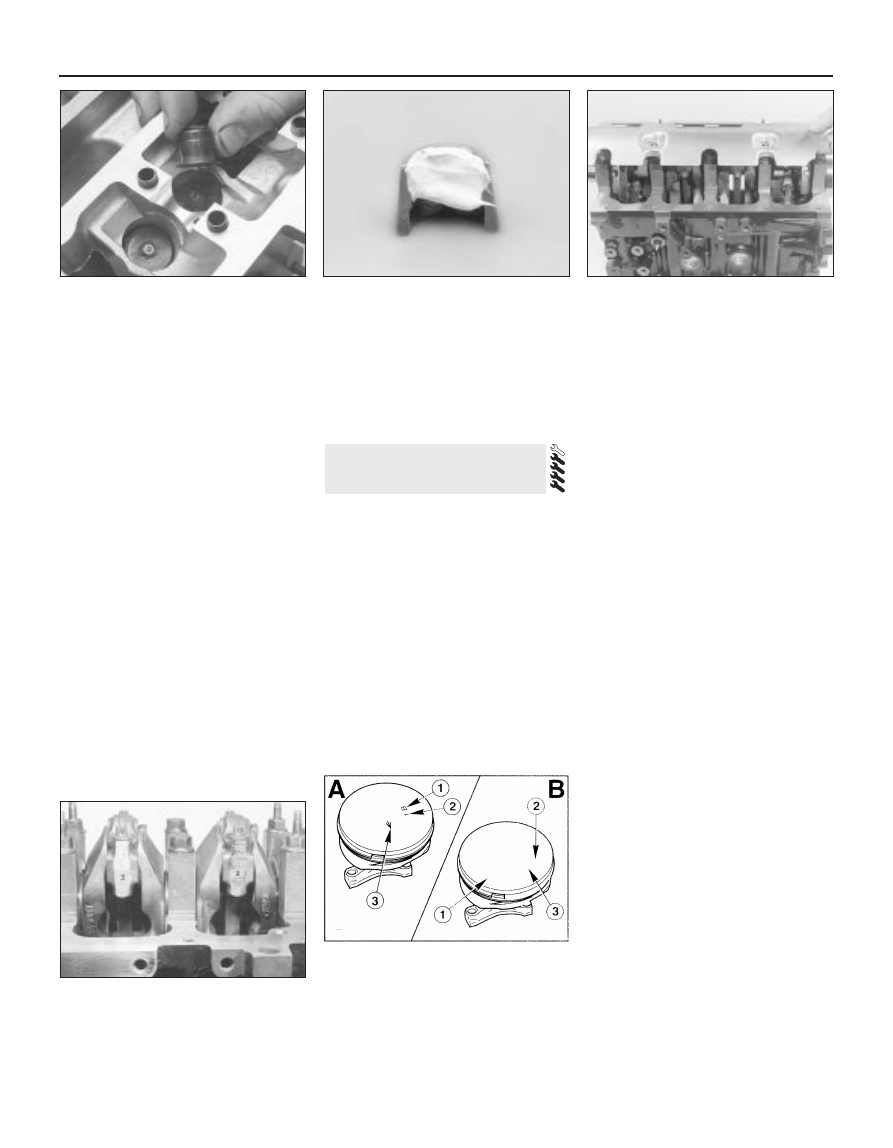
and install the first valve. Apply molybdenum
disulphide-based grease or clean engine oil to
the valve stem, and refit the valve. Where the
original valves are being re-used, ensure that
each is refitted in its original guide. If new
valves are being fitted, insert them into the
locations to which they have been ground.
3 Fit the plastic protector supplied with new
valve spring lower seat/stem oil seals to the
end of the valve stem, then put the new seal
squarely on top of the guide, and leave it
there; the action of refitting the valve spring
presses the lower seat/stem oil seal into place
(see illustration).
4 Refit the valve spring and upper seat.
5 Compress the spring with a valve spring
compressor, and carefully install the collets in
the stem groove. Apply a small dab of grease
to each collet to hold it in place if necessary
(see illustration). Slowly release the
compressor, and make sure the collets seat
properly.
6 When the valve is installed, place the
cylinder head flat on the bench and, using a
hammer and interposed block of wood, tap
the end of the valve stem gently, to settle the
components.
7 Repeat the procedure for the remaining
valves. Be sure to return the components to
their original locations - don’t mix them up!
8 Refit the hydraulic tappets (Part A of this
Chapter, Section 13).
Note: Always check first what replacement
parts are available before planning any
overhaul operation; refer to Section 1 of this
Part. A Ford dealer, or a good engine
reconditioning specialist/automotive parts
supplier, may be able to suggest alternatives
which will enable you to overcome the lack of
replacement parts.
Note: While this task is theoretically possible
when the engine is in place in the vehicle, in
practice, it requires so much preliminary
dismantling, and is so difficult to carry out due
to the restricted access, that owners are
advised to remove the engine from the vehicle
first. In addition to the new gaskets and other
replacement parts required, a hoist will be
needed. Alternatively, an adjustable engine
support bar, fitting into the water drain
channels on each side of the bonnet aperture,
and having a hook which will engage the
engine lifting eyes and allow the height of the
engine to be adjusted, could be used. Lifting
equipment such as this can be hired from
most tool hire shops - be sure that any such
equipment is rated well in excess of the
combined weight of the engine/transmission
unit.
1 Remove the cylinder head (Part A of this
Chapter, Section 14).
2 Bolt lifting eyes to suitable points on the
engine and transmission, then attach the
lifting equipment so that the engine/
transmission unit is supported securely.
3 Remove the sump (Part A of this Chapter,
Section 15).
4 Undo the screws securing the oil pump
pick-up/strainer pipe to the pump, then
unscrew the four nuts, and withdraw the oil
pump pick-up/strainer pipe and oil baffle (see
illustration).
5 Temporarily refit the crankshaft pulley, so
that the crankshaft can be rotated. Note that
each piston/connecting rod assembly can be
identified by its cylinder number (counting
from the timing belt end of the engine) etched
into the flat-machined surface of both the
connecting rod and its cap. The numbers are
visible from the front (exhaust side) of the
engine. Furthermore, each piston has an
arrow stamped into its crown, pointing
towards the timing belt end of the engine. If
no marks can be seen, make your own before
disturbing any of the components, so that you
can be certain of refitting each
piston/connecting rod assembly the right way
round, to its correct (original) bore, with the
cap also the right way round (see
illustrations).
6 Use your fingernail to feel if a ridge has
formed at the upper limit of ring travel (about a
quarter-inch down from the top of each
cylinder). If carbon deposits or cylinder wear
have produced ridges, they must be
completely removed with a special tool (see
illustration). Follow the manufacturer’s
manuals provided with the tool. Failure to
remove the ridges before attempting to
9 Piston/connecting rod
assemblies - removal
2B•12 Engine removal and general engine overhaul procedures
8.3 Valve spring pressure is sufficient to
seat lower seat/stem oil seals on
reassembly
8.5 Apply a small dab of grease to each
collet before installation - it will hold them
in place on the valve stem until the spring
is released
9.4 Removing the oil baffle to provide
access to crankshaft and bearings
9.5A Each connecting rod and big-end
bearing cap will have a flat-machined
surface visible from the front (exhaust)
side of the engine, with the cylinder
number etched in it
9.5B Piston crown markings
A 1.6 and 1.8 litre engines
B 2.0 litre engines
1 Gudgeon pin diameter grade - when used
2 Piston skirt diameter grade
3 Arrow mark - pointing to timing belt end of
engine