Ford Mondeo (petrol engines). Manual - part 85
 

  Index      Ford     Ford Mondeo - service and repair manual (petrol engines)


Search            


Content   ..  83  84  85  86   ..


Ford Mondeo (petrol engines). Manual - part 85


socket spanner of suitable size (see
illustrations)
.
48 Once the subframe is aligned as precisely
as possible, tighten its bolts to the specified
torque wrench setting without disturbing its
position. Recheck the alignment once all the
bolts are securely tightened.
49 With the subframe aligned and securely
fastened, the engine/transmission unit must
now be positioned precisely, before the
mountings can be reassembled. Ford specify
the use of service tool 21-172; this is a fixture
bolted to the subframe in place of the
engine/transmission front mounting, so that
when the mounting’s centre bolt is refitted, it
is held 60 mm above the subframe’s top
surface, and offset 20 mm to the rear of the
mounting’s subframe bolt holes (centres). DIY
mechanics are advised to obtain the Ford
tool; the only alternative is to have a copy
fabricated (see illustration).
50 Fasten the tool to the subframe in place of
the engine/transmission front mounting, and
lightly tighten the mounting’s centre bolt. Refit
the engine/transmission mountings in the
following sequence:
(a) Tighten the left-hand mounting’s nuts to

the specified torque wrench setting - do
not allow the mounting to twist as it is
tightened (see illustration).

(b) Tighten the right-hand mounting’s four

bracket-to-engine nuts to the specified
torque wrench setting.

(c) Slowly release the hoist so that the weight

of the engine/transmission unit is taken by
the mountings.

(d) Tighten the right-hand mounting’s two

bracket-to-mounting nuts to the specified
torque wrench setting - do not allow the
mounting to twist as it is tightened (see
illustration)
.

(e) Reassemble the engine/transmission rear

mounting, tightening the fasteners to the
specified torque wrench settings; tighten
the centre bolt last.

(f)

Refit the steering gear to the subframe; if
the Ford service tool is used to tighten the
bolts from underneath the vehicle (see
Chapter 10 for details), note that a torque
wrench which can tighten in an anti-
clockwise direction will be required.

(g) Unbolt the special tool from the front

mounting, refit the mounting - do not
forget the wiring connector bracket - and
tighten first the mounting’s bolts/nuts,
then its centre bolt, to their respective
specified torque wrench settings (see
illustrations)
.

51 Refit the bottom mounting rubbers to the
radiator - ensure that both are the correct way
up - then refit the radiator mounting brackets
to the subframe, ensuring that each is
returned to its correct (marked) location, and
tightening the bolts to the torque wrench
setting specified. Remove the split pins, and
secure the coolant hose connections (where
necessary).
52

Refit the air conditioning accumulator/

dehydrator (where appropriate) to the
subframe.
53 Tighten the two bolts securing the power
steering system pipes to the right-hand side
of the subframe.
54 Fasten each front suspension lower arm
balljoint and track rod end to their respective
steering knuckles, and both anti-roll bar links
to their respective suspension strut. Note the
flexible brake hose bracket attached to each
link stud (see Chapter 10 for details).
55 Where the vehicle is fitted with manual
transmission, swivel the linkage around to the
front, tighten its rear fasteners, then refit the

2B•8 Engine removal and general engine overhaul procedures

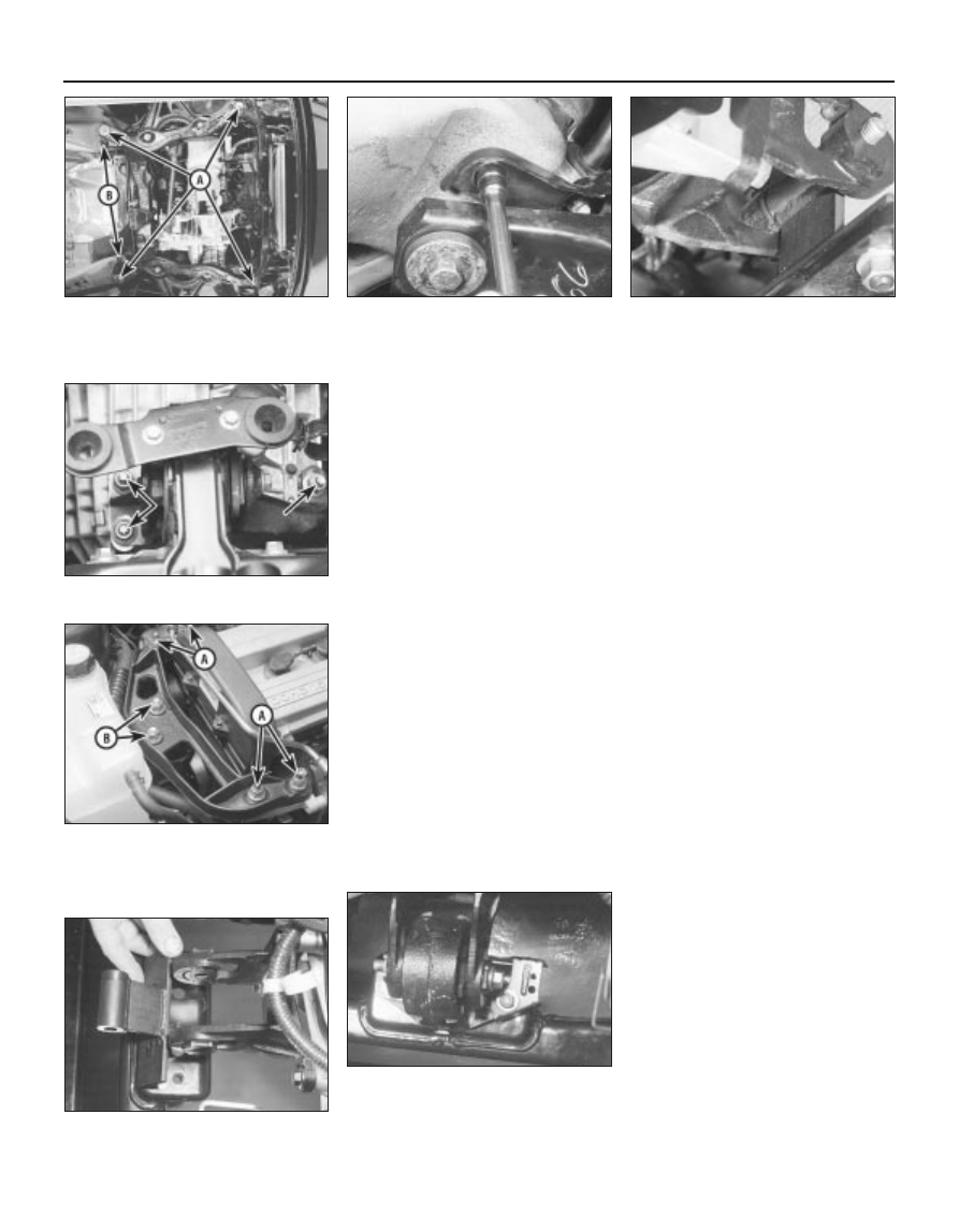
4.47A  Tighten subframe mounting 

bolts (A) while ensuring that alignment

remains correct - Ford service tools (B)

shown in use here . . .

4.47B  . . . but alternative methods using

ordinary hand tools can achieve
acceptable alignment, with care

4.49  Special tool required to hold

engine/transmission unit precisely, so that

mountings can be tightened into correct

position

4.50B  Tighten the right-hand mounting’s

four bracket-to-engine nuts (A), release

the hoist, then tighten the two bracket-to-

mounting nuts (B). Do not allow mounting

to twist

4.50A  Do not allow the left-hand mounting

to twist as its nuts (arrowed) are tightened

4.50C  Unbolt special tool . . .

4.50D  . . . then refit front mounting - do

not forget wiring connector bracket -

tighten the mounting’s nuts first, then its

centre bolt

gear linkage heat shield. Reconnect the
gearchange linkage and transmission support
rods to the transmission, adjusting the linkage
using the marks made on removal (see
Chapter 7, Part A, for details).
56 Re-install the remaining components and
fasteners in the reverse order of removal.
57 Add coolant, engine oil and transmission
fluids as needed (see Chapter 1).
58 Run the engine, and check for proper
operation and the absence of leaks. Shut off
the engine, and recheck the fluid levels.
59 Remember that, since the front suspension
subframe and steering gear have been
disturbed, the wheel alignment and steering
angles must be checked fully and carefully as
soon as possible, with any necessary
adjustments being made. This operation is best
carried out by an experienced mechanic, using
proper checking equipment; the vehicle should
therefore be taken to a Ford dealer or similarly-
qualified person for attention.

It is much easier to dismantle and work on
the engine if it is mounted on a portable engine
stand. These stands can often be hired from a
tool hire shop. Before the engine is mounted
on a stand, the flywheel/driveplate should be
removed (Part A of this Chapter, Section 21)
so that the stand bolts can be tightened into
the end of the cylinder block/crankcase.
If a stand is not available, it is possible to
dismantle the engine with it mounted on
blocks, on a sturdy workbench or on the floor.
Be extra-careful not to tip or drop the engine
when working without a stand.
If you are going to obtain a reconditioned
engine, all external components must be
removed first, to be transferred to the
replacement engine (just as they will if you are
doing a complete engine overhaul yourself).
Note:

When removing the external

components from the engine, pay close
attention to details that may be helpful or
important during refitting. Note the fitted
position of gaskets, seals, spacers, pins,
washers, bolts and other small items. 
These
external components include the following:
(a) Alternator and brackets (Chapter 5).
(b) HT leads and spark plugs (Chapter 1).
(c) Thermostat and housing (Chapter 3).
(d) Dipstick tube.
(e) Fuel injection system components

(Chapter 4).

(f)

All electrical switches and sensors - refer
to the appropriate Chapter.

(g) Inlet and exhaust manifolds (Part A of this

Chapter).

(h) Oil filter (Chapter 1).
(i)

Engine/transmission mounting brackets
(Part A of this Chapter, Section 22).

(j)

Flywheel/driveplate (Part A of this
Chapter, Section 21).

If you are obtaining a “short” engine (which

consists of the engine cylinder
block/crankcase, crankshaft, pistons and
connecting rods all assembled), then the
cylinder head, sump, oil pump, and timing belt
will have to be removed also.
If you are planning a complete overhaul, the
engine can be dismantled and the internal
components removed in the following order.
(a) Inlet and exhaust manifolds (Part A of this

Chapter).

(b) Timing belt, toothed pulleys and

tensioner, and timing belt inner cover
(Part A of this Chapter).

(c) Cylinder head (Part A of this Chapter,

Section 14).

(d) Flywheel/driveplate (Part A of this

Chapter, Section 21).

(e) Sump (Part A of this Chapter, Section 15).
(f)

Oil pump (Part A of this Chapter, Sec-
tion 16).

(g) Piston/connecting rod assemblies

(Section 9).

(h) Crankshaft (Section 10).
Before beginning the dismantling and

overhaul procedures, make sure that you have
all of the correct tools necessary. Refer to the
introductory pages at the beginning of this
manual for further information.

Note: New and reconditioned cylinder heads
are available from the manufacturers, and
from engine overhaul specialists. Due to the
fact that some specialist tools are required for
the dismantling and inspection procedures,
and new components may not be readily
available (refer to Section 1 of this Part), it may
be more practical and economical for the
home mechanic to purchase a reconditioned
head, rather than to dismantle, inspect and
recondition the original head.
Remove the camshafts and hydraulic
tappets (Part A of this Chapter, Section 13),
being careful to store the hydraulic tappets as
described (see illustration).

6 Cylinder head - dismantling

5 Engine overhaul 

dismantling sequence

Engine removal and general engine overhaul procedures  2B•9

2B

6.1  Cylinder head components

1  Hydraulic tappet
2  Valve collets
3  Valve spring upper seat
4  Valve spring

5  Valve spring lower 

seat/stem oil seal

6  Oil-retaining valve
7  Engine lifting eye
8  Cylinder head gasket

9  Inlet valve

10  Locating dowels
11  Exhaust valve
12  Cylinder head bolt

Remove the cylinder head (Part A of this
Chapter, Section 14).
Using a valve spring compressor, compress
each valve spring in turn until the split collets
can be removed. A special valve spring
compressor will be required, to reach into the
deep wells in the cylinder head without risk of
damaging the hydraulic tappet bores; such
compressors are now widely available from
most good motor accessory shops. Release
the compressor, and lift off the spring upper
seat and spring (see illustrations).
If, when the valve spring compressor is
screwed down, the spring upper seat refuses
to free and expose the split collets, gently tap
the top of the tool, directly over the upper
seat, with a light hammer. This will free the
seat.
Withdraw the valve through the combustion

chamber. If it binds in the guide (won’t pull
through), push it back in, and de-burr the area
around the collet groove with a fine file or
whetstone; take care not to mark the
hydraulic tappet bores.
Ford recommend the use of their service
tool 21-160 to extract the valve spring lower
seat/stem oil seals; while this is almost
indispensable if the seals are to be removed
without risk of (extremely expensive) damage
to the cylinder head, we found that a
serviceable substitute can be made from a
strong spring of suitable size. Screw on the
tool or spring so that it bites into the seal, then
draw the seal off the valve guide (see
illustrations)
.
It is essential that the valves are kept
together with their collets, spring seats and
springs, and in their correct sequence (unless
they are so badly worn that they are to be
renewed). If they are going to be kept and
used again, place them in a labelled polythene
bag or similar small container (see
illustration)
. Note that No 1 valve is nearest to
the timing belt end of the engine.
If the oil-retaining valve is to be removed (to
flush out the cylinder head oil galleries
thoroughly), seek the advice of a Ford dealer
as to how it can be extracted; it may be that
the only course of action involves destroying
the valve as follows. Screw a self-tapping
screw into its ventilation hole, and use the
screw to provide purchase with which the
valve can be drawn out; a new valve must be
purchased and pressed into place on
reassembly 

(see illustration).

Note: Always check first what replacement
parts are available before planning any
overhaul operation; refer to Section 1 of this
Part. A Ford dealer, or a good engine
reconditioning specialist/automotive parts
supplier, may be able to suggest alternatives
which will enable you to overcome the lack of
replacement parts.
Thorough cleaning of the cylinder head and
valve components, followed by a detailed
inspection, will enable you to decide how
much valve service work must be carried out
during the engine overhaul. Note: If the
engine has been severely overheated, it is best
to assume that the cylinder head is warped,
and to check carefully for signs of this.

Cleaning

Scrape away all traces of old gasket
material and sealing compound from the
cylinder head (see Part A of this Chapter,
Section 14 for details).
Scrape away the carbon from the
combustion chambers and ports, then wash
the cylinder head thoroughly with paraffin or a
suitable solvent.

7 Cylinder head and valve

components 
cleaning and inspection

2B•10 Engine removal and general engine overhaul procedures

6.3A  Standard valve spring compressor

modified as shown . . .

6.3B  . . . or purpose-built special version,

is required to compress valve springs

without damaging cylinder head . . .

6.3C  . . . so that both valve split collets

can be removed from the valve’s stem -

small magnetic pick-up tool prevents loss

of small metal components on removal

and refitting

6.6B  . . . can be replaced by home-made

tool if suitable spring can be found

6.6A  Ford service tool in use to remove

valve spring lower seat/stem oil seals . . .

6.7  Use clearly-marked containers to

identify components and to keep matched

assemblies together

6.8  Cylinder head oil-retaining valve

(arrowed)

Scrape off any heavy carbon deposits that
may have formed on the valves, then use a
power-operated wire brush to remove
deposits from the valve heads and stems.

Inspection

Note: Be sure to perform all the following
inspection procedures before concluding that
the services of a machine shop or engine
overhaul specialist are required. Make a list of
all items that require attention.

Cylinder head

Inspect the head very carefully for cracks,
evidence of coolant leakage, and other
damage. If cracks are found, a new cylinder
head should be obtained.
Use a straight edge and feeler blade to
check that the cylinder head gasket surface is
not distorted (see illustration). If it is, it may
be possible to re-surface it.
Examine the valve seats in each of the
combustion chambers. If they are severely
pitted, cracked or burned, then they will need
to be renewed or re-cut by an engine overhaul
specialist. If they are only slightly pitted, this
can be removed by grinding-in the valve
heads and seats with fine valve-grinding
compound, as described below.
If the valve guides are worn, indicated by a
side-to-side motion of the valve, new guides

must be fitted. Measure the diameter of the
existing valve stems (see below) and the bore
of the guides, then calculate the clearance,
and compare the result with the specified
value; if the clearance is excessive, renew the
valves or guides as necessary.
The renewal of valve guides is best carried
out by an engine overhaul specialist.
10 If the valve seats are to be re-cut, this
must be done only after the guides have been
renewed.

Valves

11 Examine the head of each valve for
pitting, burning, cracks and general wear, and
check the valve stem for scoring and wear
ridges. Rotate the valve, and check for any
obvious indication that it is bent. Look for pits
and excessive wear on the tip of each valve
stem. Renew any valve that shows any such
signs of wear or damage.
12 If the valve appears satisfactory at this
stage, measure the valve stem diameter at
several points, using a micrometer (see
illustration)
. Any significant difference in the
readings obtained indicates wear of the valve
stem. Should any of these conditions be
apparent, the valve(s) must be renewed.
13 If the valves are in satisfactory condition,
they should be ground (lapped) into their
respective seats, to ensure a smooth gas-
tight seal. If the seat is only lightly pitted, or if
it has been re-cut, fine grinding compound
only should be used to produce the required
finish. Coarse valve-grinding compound
should not be used unless a seat is badly
burned or deeply pitted; if this is the case, the
cylinder head and valves should be inspected
by an expert, to decide whether seat re-
cutting, or even the renewal of the valve or
seat insert, is required.
14 Valve grinding is carried out as follows.
Place the cylinder head upside-down on a
bench, with a block of wood at each end to
give clearance for the valve stems.
15 Smear a trace of (the appropriate grade
of) valve-grinding compound on the seat face,
and press a suction grinding tool onto the
valve head. With a semi-rotary action, grind
the valve head to its seat, lifting the valve
occasionally to redistribute the grinding

compound (see illustration). A light spring
placed under the valve head will greatly ease
this operation.
16 If coarse grinding compound is being
used, work only until a dull, matt even surface
is produced on both the valve seat and the
valve, then wipe off the used compound, and
repeat the process with fine compound. When
a smooth unbroken ring of light grey matt
finish is produced on both the valve and seat,
the grinding operation is complete. Do not
grind in the valves any further than absolutely
necessary, or the seat will be prematurely
sunk into the cylinder head.
17 When all the valves have been ground-in,
carefully wash off all traces of grinding
compound, using paraffin or a suitable
solvent, before reassembly of the cylinder
head.

Valve components

18 Examine the valve springs for signs of
damage and discolouration, and also measure
their free length by comparing each of the
existing springs with a new component.
19 Stand each spring on a flat surface, and
check it for squareness (see illustration). If
any of the springs are damaged, distorted, or
have lost their tension, obtain a complete set
of new springs.
20 Check the spring upper seats and collets
for obvious wear and cracks. Any
questionable parts should be renewed, as
extensive damage will occur if they fail during
engine operation. Any damaged or
excessively-worn parts must be renewed; the
valve spring lower seat/stem oil seals must be
renewed as a matter of course whenever they
are disturbed.
21 Check the hydraulic tappets as described
in Part A of this Chapter, Section 13.

Regardless of whether or not the head was
sent away for repair work of any sort, make
sure that it is clean before beginning
reassembly. Be sure to remove any metal
particles and abrasive grit that may still be
present from operations such as valve

8 Cylinder head - reassembly

Engine removal and general engine overhaul procedures  2B•11

2B

7.12  Measuring the diameter of a valve

stem - if any significant difference is found

in the readings obtained, excessive valve

stem wear is indicated

7.15  Grinding-in a valve seat - do not grind

in the valves any more than absolutely

necessary, or their seats will be

prematurely sunk into the cylinder head

7.19  Check each valve spring for

squareness

7.6  Check the cylinder head gasket

surfaces for warpage, in the planes

indicated (A to G). Try to slip a feeler

gauge under the precision straight edge

(see the Specifications for the maximum

distortion allowed, and use a feeler blade

of that thickness)


Content   ..  83  84  85  86   ..