Ford Mondeo (petrol engines). Manual - part 56
1 A compact disc (CD) player is available as
an optional extra on most models. On some
models, an autochanger version is available,
which can hold a number of discs at a time.
Removal
2 The battery negative (earth) lead should be
disconnected before commencing work.
CD player, or autochanger control
unit
3 The procedure is identical to that for the
radio/cassette player described in Section 23.
CD player autochanger
4 The CD player autochanger unit is mounted
on the right-hand side of the luggage
compartment. The wiring loom passes up the
“C” pillar, across to the left-hand side “A”
pillar, then to the centre console area.
5 Remove the trim cover from the
autochanger unit.
6 Unscrew the mounting screws, and remove
the autochanger unit from its mounting
bracket.
7 Disconnect the multi-plug and remove the
unit from inside the vehicle.
Refitting
8 Refitting is a reversal of the removal
procedure.
Removal
1 Remove the door trim panel as described in
Chapter 11.
2 Unscrew the cross-head screws, and
withdraw the speaker from the door inner
panel.
3 Disconnect the wiring and remove the
speaker.
Refitting
4 Refitting is a reversal of the removal
procedure.
Removal
1 Prise out the trim cover from the headlining
immediately below the base of the aerial.
2 Unscrew the cross-head screw from the
base of the aerial, and remove the aerial mast.
Refitting
3 Refitting is a reversal of the removal
procedure.
Warning: Handle the air bag unit
with extreme care, as a
precaution against personal
injury, and always hold it with the
cover facing away from the body. If in
doubt concerning any proposed work
involving the air bag unit or its control
circuitry, consult a Ford dealer or other
qualified specialist.
Removal
1 Disconnect the battery negative (earth) lead
(refer to Chapter 5, Section 1).
Warning: Before proceeding, wait
a minimum of 15 minutes, as a
precaution against accidental
firing of the air bag unit. This
period ensures that any stored energy in
the back-up capacitor is dissipated.
2 Rotate the steering wheel so that one of the
mounting bolt holes is visible above the
steering column upper shroud.
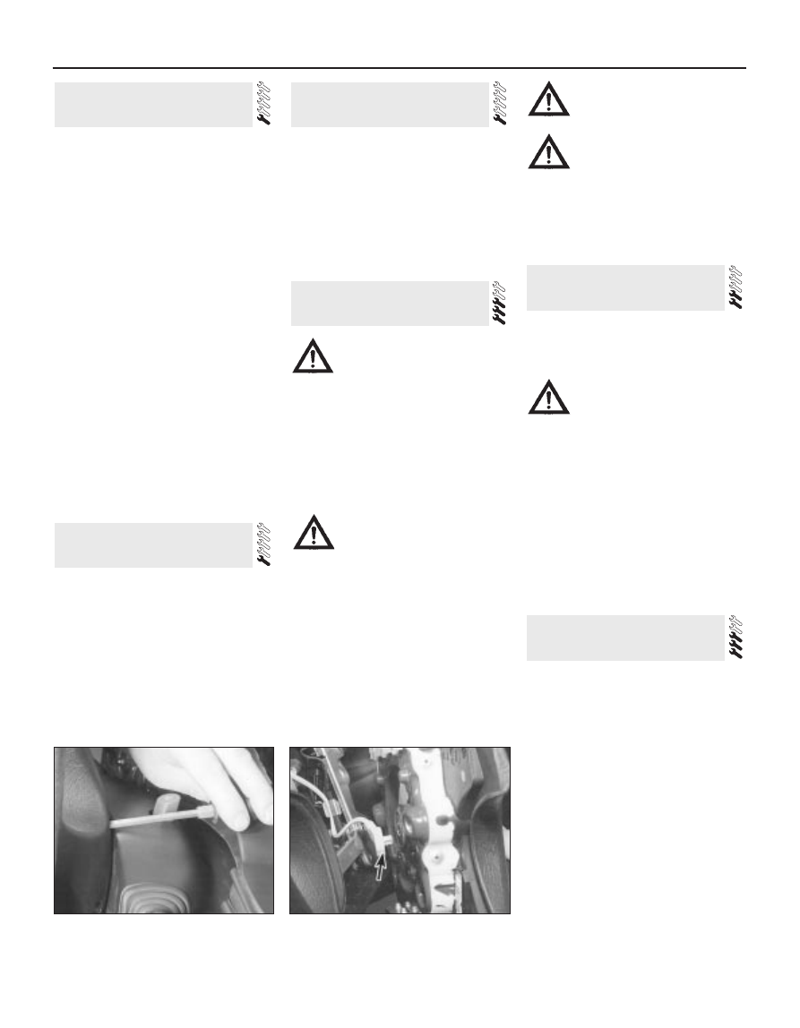
3 Unscrew and remove the first mounting
bolt, then turn the steering wheel as
necessary and remove the remaining
mounting bolts (see illustration).
4 Carefully withdraw the air bag unit from the
steering wheel far enough to disconnect the
wiring multi-plug, then remove it from inside
the vehicle (see illustration).
Warning: Stand the unit with the
cover uppermost, and do not
expose it to heat sources in
excess of 100ºC.
Warning: Do not attempt to open
or repair the air bag unit, or apply
any electrical current to it. Do not
use any air bag unit which is visibly
damaged or which has been tampered
with.
Refitting
5 Refitting is a reversal of the removal
procedure.
Removal
1 Disconnect the battery negative (earth) lead
(refer to Chapter 5, Section 1).
Warning: Before proceeding, wait
a minimum of 15 minutes, as a
precaution against accidental
firing of the air bag unit. This
period ensures that any stored energy in
the back-up capacitor is dissipated.
2 Remove the facia panel as described in
Chapter 11.
3 Disconnect the multi-plug from the module,
by pressing the locking tab upwards and
swivelling the retaining strap.
4 Unscrew the mounting bolts and remove
the module from the vehicle.
Refitting
5 Refitting is a reversal of the removal
procedure.
Removal
1 Remove the air bag unit as described in
Section 28.
2 Disconnect the horn switch multi-plug.
3 If fitted, disconnect the multi-plugs for the
cruise control.
4 Remove the steering wheel and shrouds.
5 Using a small screwdriver, release the
retaining tabs, then remove the clock spring
from the steering column.
Refitting
6 Refitting is a reversal of the removal
procedure, but make sure that the steering
wheel is centralised. The clock spring must be
fitted in its central position, with the special
alignment marks aligned and the TOP mark
uppermost. To check for this position, turn the
clock spring housing anti-clockwise until it is
tight, then turn in the opposite direction by
two-and-three-quarter turns.
30 Air bag clock spring -
removal and refitting
29 Air bag control module -
removal and refitting
28 Air bag unit (driver’s side) -
removal and refitting
27 Radio aerial -
removal and refitting
26 Speakers -
removal and refitting
25 Compact disc player -
removal and refitting
12•22 Body electrical system
28.3 Unscrewing an air bag mounting bolt
28.4 Disconnecting the air bag wiring
multi-plug (arrowed)