Ford Mondeo (petrol engines). Manual - part 54
 

  Index      Ford     Ford Mondeo - service and repair manual (petrol engines)


Search            


Content   ..  52  53  54  55   ..


Ford Mondeo (petrol engines). Manual - part 54


Where fitted, remove the clock as
described in Section 13.
Where fitted, remove the trip computer
module as described in Section 18.
Remove the heated rear window switch as
described in Section 4.
Where fitted, remove the heated
windscreen switch.
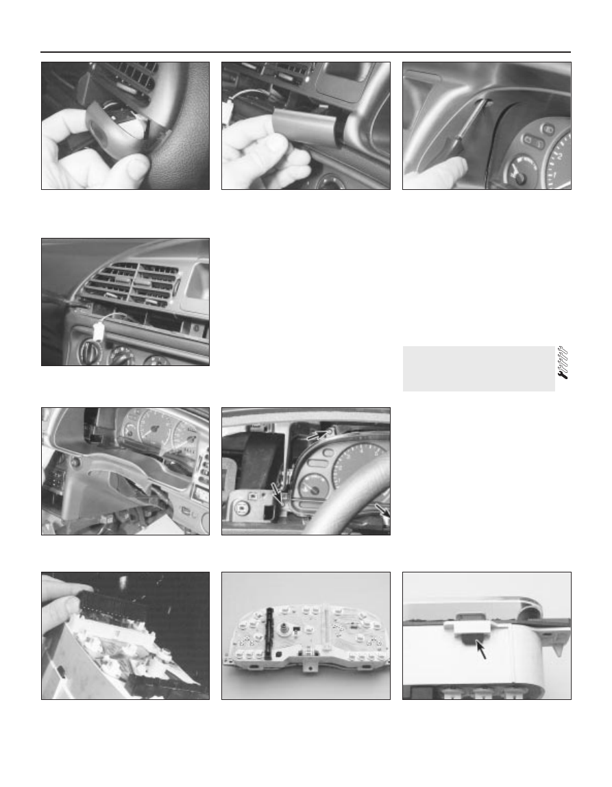
Where fitted, remove the display assembly
warning indicator for the foglights (see
illustration)
.
Remove any blanking covers from the
unused switch positions (see illustration).
Prise out the blanking covers, then unscrew
the retaining screws and remove the
instrument panel surround (see illustrations).
Unscrew the mounting screws, and

withdraw the instrument panel a little way
from the facia (see illustration).
10 Disconnect the two multi-plugs from the
rear of the instrument panel (see illustration).
11 Withdraw the instrument panel from the
facia, at the same time releasing the
speedometer intermediate cable.

Refitting

12 Refitting is a reversal of the removal
procedure.

Removal

Remove the warning light and illumination
bulbs by twisting them anti-clockwise (see
illustration)
.
Carefully prise off the glass and bezel from
the front of the instrument panel, noting the
positions of the retaining lugs (see
illustration)
.
Note the positions of the five diffusers, then
remove them from the instrument panel.
To remove the speedometer head, unscrew
the three mounting screws and withdraw the
head from the housing.
To remove the tachometer, unscrew the
single screw and withdraw it from the
housing.

11 Instrument panel

components 
removal and refitting

12•14 Body electrical system

10.6  Removing the foglight warning

indicator

10.7  Removing a switch blanking cover

10.8A  With the blanking covers removed,

unscrew the concealed screws . . .

10.10  Disconnecting the multi-plugs from

the rear of the instrument panel

11.1  Rear view of the instrument panel,

showing bulbholders

11.2  Bezel retaining lug on the instrument

panel

10.8C  . . . and lift out the instrument panel

surround

10.9  Three of the instrument panel

mounting screws (arrowed)

10.8B  . . . and the remaining screws . . .

Similarly remove the fuel gauge and
temperature gauge by unscrewing the single
screws.
Remove all the pin contacts.
Using a small punch, push in the multi-plug
securing pins, and remove the multi-plugs.
Carefully lift the printed circuit from the
location dowels on the housing, taking care
not to damage it.

Refitting

10 Refitting is a reversal of the removal
procedure.

Removal

Remove the windscreen wiper arms as
described in Section 15.
With the bonnet closed, release the grille
panel upper edge from just in front of the
windscreen, by prising off the caps and
unscrewing the upper retaining screws.
Open the bonnet, and support with the
stay.
Pull off the sealing strip from the cross
panel at the rear of the engine compartment.
Unscrew the lower screws, and remove the
grille panel halves from in front of the

windscreen, withdrawing first one side and
then the other.
Disconnect the battery negative (earth) lead
(refer to Chapter 5, Section 1).
Reach in behind the bulkhead. Squeeze the
collar on the upper end of the speedometer
cable, where it is attached to the intermediate
cable from the rear of the speedometer head.
Disconnect the cable, and withdraw it from
the bulkhead inner panel, together with the
rubber grommet (see illustrations).
Apply the handbrake, jack up the front of
the vehicle and support it on axle stands.
Unscrew the nut and disconnect the
speedometer cable from the vehicle speed
sensor on the transmission, then withdraw the
cable from within the engine compartment.
Use two spanners to loosen the nut - one to
counterhold the sensor, and the other to
unscrew the cable nut (see illustrations).

Refitting

10 Refitting is a reversal of the removal
procedure.

Removal

Disconnect the battery negative (earth) lead
(refer to Chapter 5, Section 1).

Using a small screwdriver, prise the clock
out of the facia (see illustration). To prevent
damage to the facia, place a cloth pad
beneath the screwdriver.
Disconnect the multi-plug from the rear of
the clock, and withdraw the clock (see
illustration)
.

Refitting

Refitting is a reversal of the removal
procedure. Reset the clock on completion.

Removal

Apply the handbrake, jack up the front of
the vehicle and support it on axle stands.
Unscrew the bolts, and release the clips
securing the radiator lower cover to the front
of the vehicle.
Disconnect the wiring from the horn
terminal.
Unscrew the mounting bolt, and withdraw
the horn with its mounting bracket from under
the vehicle (see illustration).

Refitting

Refitting is a reversal of the removal
procedure.

14 Horn - removal and refitting

13 Clock - removal and refitting

12 Speedometer drive cable -

removal and refitting

Body electrical system  12•15

12

12.9B  . . . and disconnect the

speedometer cable from the vehicle speed

sensor

13.2  Prising the clock out of the facia

13.3  Disconnecting the multi-plug from

the rear of the clock

12.7A  Squeeze the collar . . .

12.7B  . . . and disconnect the

speedometer main cable from the

intermediate cable

12.9A  Unscrew the cable nut . . .

Removal

Disconnect the battery negative (earth) lead
(refer to Chapter 5, Section 1). If the windscreen
wiper arms are to be removed, close the bonnet.
With the wiper(s) “parked” (ie in the normal
at-rest position), mark the positions of the
blade(s) on the screen, using a wax crayon or
strips of masking tape.
Lift up the plastic cap from the bottom of
the wiper arm, and loosen the nut one or two
turns (see illustration).
Lift the wiper arm, and release it from the
taper on the spindle by moving it to one side.

Completely remove the nut, and withdraw the
wiper arm from the spindle (see illustration).

Refitting

Refitting is a reversal of the removal
procedure. Make sure that the arm is fitted in
the previously-noted position.

Removal

Disconnect the battery negative (earth) lead
(refer to Chapter 5, Section 1).
Remove the wiper arms as described in
Section 15.
With the bonnet closed, release the grille

panel upper edge from just in front of the
windscreen, by prising off the caps and
unscrewing the upper retaining screws (see
illustrations)
.
Open the bonnet, and support it with the
stay.
Pull off the bonnet sealing strip from the
cross panel at the rear of the engine
compartment 

(see illustration).

Unscrew the lower screws, and remove the
grille panel halves from in front of the
windscreen, withdrawing one side then the
other side (see illustrations).
Unscrew the mounting bolts securing the
wiper motor and linkage to the bulkhead. On
right-hand-drive models, the linkage is on the
right-hand side of the bulkhead (see
illustration)
; on left-hand-drive models, it is
on the left-hand side.

16 Windscreen wiper motor and

linkage - removal and refitting

15 Wiper arms 

removal and refitting

12•16 Body electrical system

14.4  Horn and mounting bracket (arrowed)

15.3  Loosening the wiper arm retaining

nut

15.5  Removing the wiper arm from the

spindle

16.6A  Unscrew the lower screws . . .

16.6B  . . . and remove the grille panel from

in front of the windscreen

16.7  Wiper motor mounting bolt locations

(right-hand-drive)

16.3A  Prise off the cap . . .

16.3B  . . . and remove the upper retaining

screws

16.5  Removing the bonnet sealing strip

Disconnect the wiper motor multi-plug.
Withdraw the wiper motor, complete with
the linkage, from the bulkhead (see
illustration)
.
10 Mark the position of the motor arm on the
mounting plate, then unscrew the centre nut
(see illustration).
11 Unscrew the motor mounting bolts, and
separate the motor from the linkage assembly.

Refitting

12 Refitting is a reversal of the removal
procedure. There are two tightening torques
for the motor mounting bolts - the lower one
for bolts that are being re-inserted into an old
motor, and the higher ones for bolts that are
being inserted into a new motor. Make sure
that the wiper motor is in its “parked” position
before fitting the motor arm, and check that
the wiper linkage is in line with the motor arm.

Removal

Disconnect the battery negative (earth) lead
(refer to Chapter 5, Section 1).
Remove the tailgate wiper arm as
described in Section 15.
Remove the tailgate inner trim panel by
unscrewing the retaining screws.
Release the multi-plug from the clip, then
disconnect it (see illustration).

Disconnect the wiper motor earth lead.
Unscrew the mounting bolts, and remove
the wiper motor from inside the tailgate (see
illustrations)
.
Unbolt and remove the mounting plate. If
necessary, remove the mounting rubbers for
renewal (see illustrations).

Refitting

Refitting is a reversal of the removal
procedure. Make sure that the wiper motor is
in its “parked” position before fitting the wiper
arm.

Removal

Disconnect the battery negative (earth) lead
(refer to Chapter 5, Section 1).
Using a small screwdriver, prise the trip
computer module out of the facia. To prevent
damage to the facia, place a cloth pad
beneath the screwdriver.
Disconnect the multi-plug from the rear of
the trip computer module, and withdraw the
unit.
If necessary, the bulb can be removed by
twisting it anti-clockwise.

Refitting

Refitting is a reversal of the removal
procedure.

Some models are fitted with an auxiliary
warning system, which monitors brake lights,
sidelights, dipped beam and tail lights,
external temperature, and door/tailgate/
bootlid opening. An engine oil level warning
light on the instrument panel is also part of the
system.
The auxiliary warning system module and
graphic warning display are combined into
one unit.

Service interval reminder

The system also includes a service interval
reminder warning light, which is illuminated if

19 Auxiliary warning system -

general information and
component renewal

18 Trip computer module -

removal and refitting

17 Tailgate wiper motor 

assembly - removal and refitting

Body electrical system  12•17

12

17.6B  . . . and remove the tailgate wiper

motor assembly (Hatchback shown -

Estate similar)

17.7A  Tailgate wiper motor assembly and

mounting plate

17.7B  A mounting rubber removed from

the mounting plate

17.6A  Unscrew the mounting bolts . . .

16.9  Removing the wiper motor and

linkage

16.10  Wiper motor arm and mounting

plate located on the motor

17.4  Disconnecting the tailgate wiper

motor multi-plug


Content   ..  52  53  54  55   ..