Ford Mondeo (petrol engines). Manual - part 52
functions of the various relays are given in the
Specifications (see illustration).
8 If a component controlled by a relay
becomes inoperative and the relay is suspect,
listen to the relay as the circuit is operated. If
the relay is functioning, it should be possible
to hear it click as it is energized. If the relay
proves satisfactory, the fault lies with the
components or wiring of the system. If the
relay is not being energized, then either the
relay is not receiving a switching voltage, or
the relay itself is faulty. (Do not overlook the
relay socket terminals when tracing faults.)
Testing is by the substitution of a known good
unit, but be careful; while some relays are
identical in appearance and in operation,
others look similar, but perform different
functions.
9 The central timer module located on the
bottom of the main fusebox incorporates its
own self-diagnosis function. Note that
diagnosis cannot take place if the heated rear
window is defective.
10 To activate the system, press the heated
rear window button while the ignition is being
switched on, then release the button. Operate
the light switch, washer pump switch and all
of the door switches one after the other, and
check that the buzzer confirms that the input
signals are correct.
11 Now move the wiper lever to the
intermittent wipe position, and check the
output signals by operating the same
switches.
12 The self-diagnosis function is turned off
by switching the ignition off and on again.
Removal
Ignition switch and lock barrel
1 Disconnect the battery negative (earth) lead
(refer to Chapter 5, Section 1).
2 Remove the rubber gaiters and locking
rings, then remove the securing screws and
take off the steering column upper and lower
shrouds.
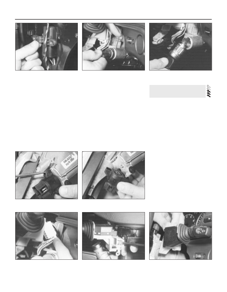
3 Insert the ignition key, and turn it to the
accessory position. Using a small screwdriver
or twist drill through the hole in the side of the
lock housing, depress the locking plunger and
withdraw the lock barrel (see illustrations).
4 The switch may be removed from the
steering column assembly by disconnecting
the multi-plug, then using a screwdriver to
release the switch retaining tab (see
illustrations).
Windscreen wiper multi-function
switch
5 Disconnect the battery negative (earth) lead
(refer to Chapter 5, Section 1).
6 Remove the rubber gaiters and locking
rings, then remove the securing screws and
take off the steering column upper shroud.
7 Disconnect the multi-plug (see illustration).
8 Depress the plastic tab with a screwdriver,
and lift the switch assembly from the steering
column (see illustrations).
4 Switches - removal and refitting
12•6 Body electrical system
3.7 “One-touch down” window relay in the
driver’s door
4.3A Depress the locking plunger . . .
4.3B . . . and withdraw the ignition lock
barrel
4.7 Disconnecting the multi-plug from the
windscreen wiper multi-function switch
4.8A Depress the plastic tab with a
screwdriver . . .
4.4A Release the retaining tab . . .
4.4B . . . and remove the ignition switch
4.8B . . . and remove the windscreen wiper
multi-function switch