Ford Mondeo (petrol engines). Manual - part 43
 

  Index      Ford     Ford Mondeo - service and repair manual (petrol engines)


Search            


Content   ..  41  42  43  44   ..


Ford Mondeo (petrol engines). Manual - part 43


Using a trolley jack, support the rear lower
arm beneath the coil spring position.
Unscrew and remove the bolt securing the
rear shock absorber to the knuckle.
Where applicable, release the ABS wheel
sensor lead from the tie-bar.
Detach the handbrake cable from the tie-
bar bracket.
Refer to Chapter 9, and disconnect the
handbrake cable from the rear brake shoes or
rear caliper, as applicable. Pass the cable
through the hole in the tie-bar.
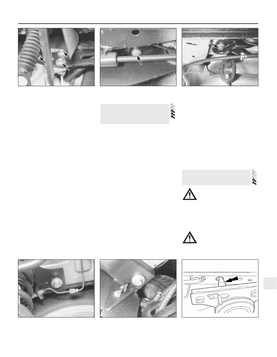
Unscrew and remove the three bolts
securing the tie-bar to the knuckle (see
illustration)
.
Unbolt the tie-bar bracket from the
underbody, and withdraw the assembly from
under the vehicle (see illustrations).
Mount the tie-bar in a vice, then unscrew
the bolt, and separate the tie-bar from its
bracket.
10 It is not possible to renew the rubber bush
in the tie-bar, and if it is excessively worn, the
complete tie-bar must be renewed.

Refitting

11 Refitting is a reversal of the removal
procedure, but delay fully tightening the bolt
which secures the arm to the bracket until the
weight of the vehicle is on the rear
suspension. On completion, check the
operation of the handbrake.

Removal

Chock the front wheels, then jack up the
rear of the vehicle and support on axles
stands. Remove both rear wheels. Make sure
that the vehicle is supported high enough for
the crossmember to be removed.
Disconnect the handbrake rear cables from
the front primary cable, as described in
Chapter 9.
Where applicable, remove the ABS wheel
sensors from the rear knuckles, and
disconnect the wiring leads from the clips as
described in Chapter 9.
Disconnect the flexible brake hoses from
the brackets on both sides of the
crossmember, as described in Chapter 9.
Working on each side of the vehicle, unbolt
the tie-bar brackets from the underbody.
Support the rear suspension crossmember
on a trolley jack.
Unscrew the mounting bolts, and lower the
crossmember to the ground (see
illustrations)
.
If necessary, remove the suspension
components from the crossmember as
described in the appropriate Sections of this
Chapter.

Refitting

Refitting is a reversal of the removal
procedure, noting the following points:
(a) When raising the crossmember, note that

guide pins are provided to ensure correct
alignment (see illustration).

(b) Delay fully tightening the suspension

mounting bolts until the weight of the
vehicle is on the rear suspension.

(c) Tighten all bolts to the specified torque.
(d) Bleed the brake hydraulic system as

described in Chapter 9.

(e) Check, and if necessary adjust, the rear

wheel toe setting as described in Section 36.

Warning: All models are equipped
with an air bag system. Make
sure that the safety

recommendations given in Chapter 12 are
followed, to prevent personal injury.

Removal

Disconnect the battery negative (earth) lead
(refer to Chapter 5, Section 1).

Warning: Before proceeding, wait
a minimum of 15 minutes, as a
precaution against accidental
firing of the air bag unit. This

period ensures that any stored energy in
the back-up capacitor is dissipated.

27 Steering wheel 

removal and refitting

26 Rear suspension

crossmember (Estate
models) 
- removal and refitting

Suspension and steering systems  10•17

10

26.7A  Rear suspension crossmember rear

mounting bolt

26.7B  Rear suspension crossmember

front mounting bolt

26.9  Guide pin (arrowed) for correct

alignment of the rear crossmember

25.7  Bolts (arrowed) securing the rear

suspension tie-bar to the knuckle

25.8A  Tie-bar bracket front bolt (arrowed)

on the underbody

25.8B  Tie-bar bracket rear bolt (arrowed)

on the underbody

Turn the steering wheel so that the front
wheels are in the straight-ahead position.
Unscrew the screws, and remove the
steering column upper and lower shrouds.
From the rear of the steering wheel,
unscrew the air bag module mounting screws. 
Carefully lift the module from the steering
wheel, and disconnect the air bag multi-plug
and horn wiring connections. 

Warning: Position the air bag
module in a safe place, with the
mechanism facing downwards as
a precaution against accidental
operation.

Make sure that the steering lock is not
engaged. Unscrew the retaining bolt from the
centre of the steering wheel (see illustration).
Remove the steering wheel from the top of

the column, while feeding the horn and air bag
wiring through the hole in the steering wheel
hub (see illustration).

Refitting

Make sure that the front wheels are still
facing straight-ahead, then locate the steering
wheel on the top of the steering column.
Refit the retaining bolt, and tighten it to the
specified torque while holding the steering
wheel (see illustration). Do not tighten the
bolt with the steering lock engaged, as this
may damage the lock.
10 Reconnect the horn wiring connections
and air bag multi-plug.
11 Locate the air bag module/horn contact
on the steering wheel, then insert the
mounting screws and tighten them.

12 Refit the steering column upper and lower
shrouds. Insert and tighten the screws.
13 Reconnect the battery negative lead.

Warning: All models are equipped
with an air bag system. Make
sure that the safety
recommendations given in

Chapter 12 are followed, to prevent
personal injury.

Removal

Disconnect the battery negative (earth) lead
(refer to Chapter 5, Section 1).

Warning: Before proceeding, wait
a minimum of 15 minutes, as a
precaution against accidental
firing of the air bag unit. This

period ensures that any stored energy in
the back-up capacitor is dissipated.
Turn the steering wheel so that the front
wheels are in the straight-ahead position.
Remove the ignition key, then turn the
steering wheel slightly as necessary until the
steering lock engages.
Unscrew the screws, and remove the
steering column lower and upper shrouds. As
the lower shroud is being removed, it will be
necessary to remove the rubber ring from the
ignition switch/steering lock (see
illustrations)
.

28 Steering column - removal,

inspection and refitting

10•18 Suspension and steering systems

27.6  Removing the steering wheel

retaining bolt

27.7  Feeding the horn and air bag wiring

through the hole in the steering wheel hub

27.9  Tightening the steering wheel

retaining bolt

28.4C  . . . and remove the lower shroud

28.4D  Upper shroud retaining screws

(arrowed)

28.4A  Unscrew the screws from the lower

shroud . . .

28.4B  . . . remove the rubber ring . . .

28.4E  Removing the upper shroud

Remove the driver’s side lower facia panel
(see Chapter 11).
Unscrew the clamp plate bolt securing the
steering column shaft to the flexible coupling.
Swivel the clamp plate around, and disengage
it from the flexible coupling stub (see
illustrations)
.
Release the cable tie from the wiring loom
at the steering column, and disconnect the
multi-plugs (see illustrations).
Unscrew and remove the steering column
mounting bolts, then slide the column
upwards to disengage the retaining tab from
the groove in the cross-beam bracket, and
withdraw it from inside the vehicle (see
illustrations)
.

Inspection

With the steering column removed, check
the universal joints for wear, and examine the

column upper and lower shafts for any signs
of damage or distortion (see illustration).
Where evident, the column should be
renewed complete.
10 Examine the height adjustment lever
mechanism for wear and damage (see
illustration)
.
11 With the steering lock disengaged, turn
the inner column, and check the upper and
lower bearings for smooth operation. The
bearings are obtainable separately, and
should be renewed if necessary. Dismantling
and reassembly of the column assembly is a
relatively easy operation.

Refitting

12 Locate the steering column on its bracket,
making sure that the tab slides down into the
groove correctly.

13 Insert the mounting bolts and tighten to
the specified torque (see illustration).
14 Reconnect the multi-plugs, and secure
the wiring loom with the cable tie.

Suspension and steering systems  10•19

10

28.9  Steering column and universal joint

28.10  Height adjustment lever mechanism

28.13  Tightening the steering column

mounting bolts

28.7C  . . . and main multi-plug from the

steering column

28.8A  Steering column mounting bolt

locations (arrowed)

28.8B  Removing the steering column

28.6A  Unscrew the clamp plate bolt . . .

28.6B  . . . and swivel the clamp plate

around

28.7A  Disconnecting the multi-plug from

the ignition switch

28.7B  Disconnecting the small 

multi-plug . . .

15 Locate the steering column shaft on the
flexible coupling, swivel the clamp plate
round, then insert the bolt and tighten to the
specified torque.
16 Refit the driver’s side lower trim panel.
17 Refit the steering column upper and lower
shrouds.
18 Reconnect the battery negative lead.

Removal

Disconnect the battery negative (earth) lead
(refer to Chapter 5, Section 1).
Turn the steering wheel so that the front
wheels are in the straight-ahead position.
Remove the ignition key, then turn the
steering wheel slightly as necessary until the
steering lock engages.
Unscrew the clamp plate bolt securing the
steering column shaft to the flexible coupling.
Swivel the clamp plate around, and disengage
it from the flexible coupling stub.
Carefully prise the rubber boot from the
bulkhead, and withdraw it into the passenger
compartment. Take care not to damage the
sealing lip of the boot.
Using an Allen key, unscrew the clamp bolt
securing the flexible coupling to the pinion
shaft on the steering gear, and withdraw the
coupling from inside the vehicle.

Refitting

Refitting is a reversal of the removal
procedure, but tighten the clamp bolts to the
specified torque. Make sure that the rubber
boot engages correctly in the bulkhead and
on the flexible coupling.

Removal

Remove the steering column flexible
coupling as described in Section 29.
Apply the handbrake, then jack up the front

of the vehicle and support it on axle stands.
Remove both front wheels.
Working beneath the vehicle, unbolt the
rear engine mounting from the transmission
and underbody.
Extract the split pins from the track rod end
balljoint nuts, then unscrew the nuts, and
detach the rods from the arms on the steering
knuckles using a conventional balljoint
removal tool. Take care not to damage the
balljoint seals.
Position a suitable container beneath the
steering gear, then unscrew the union nuts
securing the power steering fluid supply,
return, and cooler lines to the steering gear.
Identify the lines for position, then unbolt the
clamps, disconnect the lines, and allow the
fluid to drain into the container. Cover the
apertures in the steering gear and also the
ends of the fluid pipes, to prevent the ingress
of dust and dirt into the hydraulic circuit.
Unscrew and remove the steering gear
mounting bolts. The bolts are located on top
of the steering gear, and are difficult to reach.
Ideally, the special U-shaped Ford spanner
should be used, but it is just possible to reach
them with a normal spanner (see illustration).
Withdraw the steering gear through the
wheel arch.

Refitting

If the steering gear is being replaced with a
new one, the new unit will be supplied
together with union nuts already fitted. The
new nuts must only be used with new feed
and return lines - otherwise, they must be
removed and discarded. If the original lines
and union nuts are being used, the Teflon
rings on the union nuts must be renewed. To
do this, the rings must be expanded
individually onto a fitting adaptor (see
illustration)
, then located in the grooves of
the union nuts.
Locate the steering gear on the subframe,
and insert the two mounting bolts. Tighten the
bolts to the specified torque (see illustration).
Note that, if the special Ford tool is being
used, the bottom of the tool must be turned
anti-clockwise in order to tighten the
mounting bolts.

10 Remove the covers from the apertures on
the steering gear, then reconnect the fluid
lines and tighten the union nuts to the
specified torque. Refit the clamps and tighten
the bolts.
11 Refit the track rod end balljoints to the
steering knuckles, and tighten the nuts to the
specified torque. Check that the split pin
holes are aligned; if necessary, turn the nuts
to the nearest alignment, making sure that the
torque wrench setting is still within the
specified range. Insert new split pins, and
bend them back to secure.
12 Refit the rear engine mounting to the
transmission and underbody, and tighten the
bolts to the specified torque.
13 Refit the front wheels, and lower the
vehicle to the ground.
14 Refit the steering column flexible coupling
with reference to Section 29.
15 Bleed the power steering hydraulic
system as described in Section 33.
16 Have the front wheel alignment checked,
and if necessary adjusted, at the earliest
opportunity (refer to Section 36).

Removal

Disconnect the battery negative (earth) lead
(refer to Chapter 5, Section 1).
Working inside the vehicle, unscrew the
clamp plate bolt securing the steering column
shaft to the flexible coupling. Swivel the clamp
plate around, and disengage it from the
flexible coupling stub.
Apply the handbrake, then jack up the front
of the vehicle and support it on axle stands.
Remove both wheels.
On manual transmission models,
disconnect the gearchange linkage and
support rods from the transmission, as
described in Chapter 7, Part A.
Remove the exhaust downpipe complete,
as described in Chapter 4.
Remove the cover from under the radiator
by unscrewing the screws and releasing the
clips.

31 Power steering gear 

(left-hand-drive models with
ABS) 
- removal and refitting

30 Power steering gear (all except

left-hand-drive models with
ABS) 
- removal and refitting

29 Steering column flexible

coupling - removal and refitting

10•20 Suspension and steering systems

30.6  U-shaped Ford spanner for

unscrewing the steering gear mounting

bolts

30.8  Using an adaptor to fit the Teflon

rings to the union nuts

1  Adaptor      2  Teflon ring      3  Union nut
4  Groove location for the Teflon ring

30.9  Tightening the steering gear

mounting bolts using the U-shaped

spanner (arrowed)


Content   ..  41  42  43  44   ..