Ford Mondeo (petrol engines). Manual - part 41
 

  Index      Ford     Ford Mondeo - service and repair manual (petrol engines)


Search            


Content   ..  39  40  41  42   ..


Ford Mondeo (petrol engines). Manual - part 41


Refitting

12 Locate the lower arm on the subframe,
and insert the mounting bolts. Fit the nuts and
tighten them in stages, first to the specified
torque and then through the angle specified.
13 If removed, locate the tripod on the inner
end of the driveshaft in the CV joint housing,
then refit the gaiter, together with a new clip.
14 Refit the front suspension lower arm
balljoint to the knuckle assembly, and insert
the clamp bolt with its head facing forwards.
Refit the nut and tighten to the specified
torque.
15 Refit the track rod end balljoint to the
steering knuckle, and tighten the nut to the
specified torque. Check that the split pin
holes are aligned; if necessary, turn the nut to
align the holes, making sure that the torque
wrench setting is still within the specified
range. Insert a new split pin, and bend it back
to secure.
16 Swivel the anti-roll bar down, then
reconnect the links to the bar and tighten the
nuts to the specified torque.
17 If working on the right-hand side, refit the
auxiliary drivebelt cover where necessary.
18 Refit the wheel, and lower the vehicle to
the ground.

Note: If the lower arm balljoint is worn, either
the complete lower arm or the balljoint alone
can be renewed. If the balljoint has already
been renewed, it will be bolted in position; if
the original balljoint is being renewed, then it
will be riveted in position (see illustration).
This Section describes the renewal of a
riveted balljoint.

Remove the front suspension lower arm as
described in Section 7. It is not recommended
that the balljoint be replaced with the lower
arm in position on the vehicle; the accurate
drilling necessary may not be possible, and
the holes in the arm may be enlarged.
With the lower arm on the bench, use a 
3 mm drill to make a pilot hole through each of
the three rivets. Now use a 9 mm drill to drill
the rivets to a depth of 12 mm, then use a 7 or
8 mm drift to drive the rivets out of the arm.
Clean any rust or dirt from the rivet holes.
The new balljoint is supplied with a
protective plastic cover over the rubber boot
and stub, and it is recommended that this
remains in position until it is time to connect
the balljoint to the steering knuckle.
Locate the new balljoint on the lower arm,
and use three new bolts to secure it, inserting
the bolts from the top of the arm. Tighten the
nuts to the specified torque. Make sure that
the location lug on the balljoint engages the
hole in the lower arm (see illustration).
Refit the front suspension lower arm as
described in Section 7.

Note: Removal of the rear hub damages the
bearings, and renders them unserviceable for
future use. The hub and bearing assembly
must always be renewed if it is removed.

Inspection

The rear hub bearings are non-adjustable,
and are supplied complete with the hub. It is
not possible to renew the bearings separately
from the hub.
To check the bearings for excessive wear,

chock the front wheels, then jack up the rear
of the vehicle and support it on axle stands.
Fully release the handbrake.
Grip the rear wheel at the top and bottom,
and attempt to rock it. If excessive movement
is noted, or if there is any roughness or
vibration felt when the wheel is spun, it is
indicative that the hub bearings are worn.

Renewal

Remove the rear wheel.
On models fitted with rear brake drums,
remove the rear brake drum as described in
Chapter 9.
On models fitted with rear brake discs,
remove the rear brake disc as described in
Chapter 9.
On all models, tap off the dust cap and
unscrew the hub nut. Note that the nut is of
special laminated design, and should only be
re-used a maximum of 5 times. It is a good
idea to mark the nut with a file every time it is
removed. Obtain a new one if necessary.
Using a suitable puller, draw the hub and
bearing assembly off the stub axle. Note that
this procedure renders the bearings
unserviceable for future use.
Locate the new rear hub and bearing
assembly on the stub axle, then refit the hub
nut and tighten it to the specified torque.
10 Tap the dust cap fully onto the hub.
11 Refit the rear brake disc or drum as
applicable, as described in Chapter 9.
12 Refit the rear wheel, and lower the vehicle
to the ground.

9 Rear hub and bearings

(Saloon/Hatchback models) -
inspection and renewal

8 Front suspension lower arm

balljoint - renewal

Suspension and steering systems  10•9

10

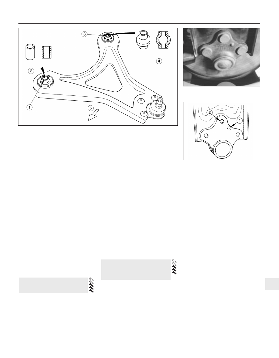
7.10  Front suspension lower arm bushes

1  Front bush
2  Cylindrical inner tube

3  Rear bush
4  Barrel-shaped inner tube

5  Front of vehicle

8.5  Location lug (1) and bolt hole (2) in the

front suspension lower arm balljoint

8.0  Original riveted front suspension lower

arm balljoint

Note: Removal of the rear hub from the
knuckle damages the bearings, and renders
them unserviceable for future use. The hub
and bearing assembly must always be
renewed if it is removed.

Removal

Chock the front wheels, then jack up the
rear of the vehicle and support it on axle
stands. Remove the appropriate rear wheel.
When applicable, remove the ABS sensor
from the knuckle as described in Chapter 9.
Remove the rear hub and bearing assembly
as described in Section 9.

Drum brake models

Fit a brake hose clamp to the flexible brake
hose, then release the clip and detach the
flexible hose from the strut. Unscrew the
union nut, and detach the rigid brake pipe
from the wheel cylinder. If preferred (to
eliminate any bleeding procedure during
refitting) the rigid brake pipe may remain
attached to the wheel cylinder, provided that
care is taken to prevent damage to both the
rigid and flexible brake pipes.
Unbolt the backplate from the rear
suspension knuckle (see illustration), and
support it to one side on an axle stand. The
brake shoes and handbrake cable can remain
attached.

Disc brake models

Unbolt the splash shield from the rear
suspension knuckle.

All models

Unscrew and remove the bolt securing the
tie-bar to the bottom of the knuckle, and
move the tie-bar downwards.
Unscrew and remove the bolts securing the
front and rear lower arms to the knuckle, and
move the arms to one side.
Support the knuckle on an axle stand, then
unscrew and remove the clamp bolt securing
the knuckle to the strut.
10 Prise the top of the knuckle apart carefully
using a large flat-bladed tool, and withdraw

the knuckle downwards from the strut.
Withdraw the knuckle from under the rear
wheel arch.

Refitting

11 Locate the knuckle fully on the strut, then
insert the clamp bolt and tighten to the
specified torque.
12 Refit the front and rear lower arms to the
knuckle, and insert the bolts finger-tight at
this stage.
13 Refit the tie-bar to the bottom of the
knuckle, and insert the bolt finger-tight at this
stage.
14 Refit the backplate (or splash shield, as
applicable) to the rear suspension knuckle,
and tighten the bolts to the specified torque.

Drum brake models

15 Reconnect the rigid brake pipe to the
wheel cylinder (if disconnected), and tighten
the union nut.
16 Attach the flexible hose to the strut, refit
the clip, and remove the hose clamp.

All models

17 Fit a new rear hub and bearing assembly
as described in Section 9.
18 Where applicable, refit the ABS sensor as
described in Chapter 9.
19 Refit the wheel, and lower the vehicle to
the ground.
20 With the weight of the vehicle on the
suspension, fully tighten the mounting bolts
for the tie-bar and lower arms.
21 Where applicable, bleed the hydraulic
brake circuit as described in Chapter 9.

Note: Before attempting to remove the rear
suspension strut, a tool to hold the coil spring
in compression must be obtained. Careful use
of conventional coil spring compressors will
prove satisfactory.

Removal

In order to remove the rear suspension
strut, the coil spring must be temporarily
compressed. This will enable the piston rod to

be retracted into the strut, and will provide
additional room for releasing the strut from
the bump stop on top of the rear suspension
crossmember. 

Warning: It is important to only
use a high-quality spring
compressor; carefully follow the
tool manufacturer’s manuals
provided with it.

Chock the front wheels, then jack up the
rear of the vehicle and support it on axle
stands. Remove the appropriate wheel.
Where fitted, unclip the ABS sensor wiring
from the strut, and remove the sensor from
the knuckle as described in Chapter 9 (see
illustration).
On models fitted with adaptive damping,
unclip the wiring from the strut and
disconnect the multi-plug (see illustration).
On drum brake models, fit a brake hose
clamp to the rear flexible brake hose, then
unscrew the union nut securing the rigid brake
pipe to the flexible hose on the strut. Extract
the clip, and disconnect the flexible hose from
the strut.
On models fitted with rear disc brakes,
unbolt the caliper from the knuckle as
described in Chapter 9, but leave the
hydraulic hose attached. Support the caliper
on an axle stand, making sure that the flexible
hose is not strained.
Unscrew the nut securing the rear anti-roll
bar link to the front lower arm on the
appropriate side. Hold the actual link with an
adjustable spanner or grips while unscrewing
the nut, to prevent damage to the link joint.
Unscrew and remove the bolt securing the
tie-bar to the bottom of the knuckle. Move the
tie-bar downwards (see illustrations).
Unscrew and remove the bolts securing the
front and rear lower arms to the knuckle, and
move the arms to one side (see illustrations).
10 Support the knuckle on a trolley jack, then
unscrew and remove the clamp bolt securing
the knuckle to the strut (see illustrations).
11 Prise the clamp on the knuckle apart
using a large flat-bladed tool. Disconnect the
knuckle from the strut, and lower it on the
trolley jack as far as possible, taking care not
to damage the handbrake cable (see
illustration).

11 Rear suspension strut

(Saloon/Hatchback models) -
removal and refitting

10 Rear suspension knuckle

(Saloon/Hatchback models) -
removal and refitting

10•10 Suspension and steering systems

10.5  Two of the bolts securing the brake

backplate to the rear suspension knuckle

11.3  Unclipping the ABS sensor wiring

from the strut

11.4  Location of the adaptive damping

lead (1) and multi-plug (2)

12 Fit the coil spring compressor tool
(ensuring that it is fully engaged), and
compress the coil spring until all tension is
relieved from the upper and lower mountings
(see illustration). This will also release the
bracket on the strut from the bump stop
rubber on the top of the rear crossmember.
13 Support the strut, then reach up under the
wheel arch, and unscrew the two bolts
securing the upper mounting to the
underbody (see illustration).
14 Slightly lift the strut, to force the piston
into the shock absorber and release the strut
bracket from the bump stop on the
crossmember. Lower the strut assembly and
withdraw it from under the vehicle (see
illustration).

Suspension and steering systems  10•11

10

11.12  Compressor tools fitted to the rear

coil spring

11.13  Bolts (arrowed) securing the strut

upper mounting to the underbody

11.14  Removing the rear suspension strut

11.10A  Support the knuckle on a trolley

jack . . .

11.10B  . . . and remove the knuckle-to-

strut clamp bolt

11.11  Separating the knuckle from the

strut

11.9A  Unscrew the bolt . . .

11.9B  . . . and remove the rear lower arm

from the knuckle

11.8A  Tie-bar mounting bolt on knuckle

11.8B  Remove the bolt . . .

11.8C  . . . and move the tie-bar

downwards

Refitting

15 Locate the strut assembly (together with
the coil spring compressor tool) under the
wheel arch, and locate the bracket on the
bump stop on the rear suspension
crossmember. Insert the two bolts securing
the upper mounting to the underbody tower,
and tighten them to the specified torque.
16 Carefully release the coil spring
compressor tool, making sure that the spring
locates correctly in the upper and lower seats,
and that the strut bracket locates on the
crossmember bump stop. The bump stop is
tapered inwards, and the strut bracket should
be fully engaged with it before releasing the
coil spring.
17 Raise the knuckle and engage it with the
strut, then insert the clamp bolt and tighten to
the specified torque.
18 Reconnect the front and rear lower arms

to the knuckle, and finger-tighten the bolts at
this stage.
19 Reconnect the tie-bar to the bottom of the
knuckle, and finger-tighten the bolt at this
stage.
20 Refit the anti-roll bar link to the lower arm,
and tighten the nut to the specified torque.
21 On disc brake models, refit the caliper
bracket to the knuckle, and tighten the
mounting bolts to the specified torque (see
Chapter 9). Make sure that the flexible brake
hose is not twisted.
22 On drum brake models, connect the
flexible hose to the strut, insert the clip, then
insert the rigid brake line and tighten the union
nut. Remove the brake hose clamp, then
bleed the hydraulic brake circuit as described
in Chapter 9.
23 Where applicable, reconnect the wiring
multi-plug for the adaptive damping, and clip
the wiring to the strut.

24 Where applicable, refit the ABS sensor as
described in Chapter 9, and clip the wiring to
the strut.
25 Refit the wheel, and lower the vehicle to
the ground.
26 With the weight of the vehicle on the rear
suspension, fully tighten the lower arm and
tie-bar mounting bolts.

The procedure is similar to that for the front
suspension strut, and reference should be made
to Section 5. Note that the spring compressor
tools will already be in position on the coil spring
following the removal operation. Refer also to
the accompanying illustrations for details of the
separate components (see illustrations).

Removal

Chock the front wheels, then jack up the
rear of the vehicle and support it on axle
stands. Remove both rear wheels.
Unscrew the nuts securing the anti-roll bar
links to the front lower arms on both sides.
Hold the upper part of the links with a spanner
while loosening the nuts. Recover the rubber
bushes (see illustrations).

13 Rear anti-roll bar and links

(Saloon/Hatchback models) -
removal and refitting

12 Rear suspension strut

(Saloon/Hatchback models) -
overhaul

10•12 Suspension and steering systems

12.1A  Rear strut dismantling - unscrew

the upper mounting nut . . .

12.1B  . . . remove the cup . . .

12.1C  . . . upper mounting bracket and

seat . . .

13.2A  Loosen the nut . . .

13.2B  . . . remove the nut and rubber 

bush . . .

12.1D  . . . gaiter and bump stop . . .

12.1E  . . . and coil spring

13.2C  . . . and remove the anti-roll bar link

from the lower arm


Content   ..  39  40  41  42   ..