Ford Mondeo (petrol engines). Manual - part 40
Since most of the procedures dealt with in
this Chapter involve jacking up the vehicle
and working underneath it, a good pair of axle
stands will be needed. A hydraulic trolley jack
is the preferred type of jack to lift the vehicle,
and it can also be used to support certain
components during removal and refitting
operations.
Warning: Never, under any
circumstances, rely on a jack to
support the vehicle while working
beneath it. When jacking up the vehicle, do
not lift or support it beneath the front or
rear subframes.
Removal
1 Apply the handbrake. Remove the wheel
cover from the relevant front wheel, and
loosen (but do not remove) the driveshaft/hub
nut. This nut is very tight.
2 Loosen the front wheel nuts, jack up the
front of the vehicle and support it on axle
stands. Remove the front wheel.
3 Extract the split pin from the track rod end
balljoint nut. Unscrew the nut, and detach the
rod from the arm on the steering knuckle
using a conventional balljoint removal tool.
Take care not to damage the balljoint seal.
4 Remove the ABS sensor (when fitted) as
described in Chapter 9.
5 Remove the brake caliper and brake disc as
described in Chapter 9, but do not disconnect
the flexible hose from the caliper. Suspend
the caliper from a suitable point under the
wheel arch, taking care not to strain the hose.
6 Unscrew and remove the driveshaft/hub
nut. Note that the nut is of special laminated
design, and should only be re-used a
maximum of 5 times. (It is a good idea to file a
small notch on the nut every time it is
removed.) Obtain a new nut if necessary.
7 Note which way round the lower arm
balljoint clamp bolt is fitted, then unscrew and
remove it from the knuckle assembly. Lever
the balljoint down from the knuckle; if it is
tight, prise the clamp open using a large flat-
bladed tool. Take care not to damage the
balljoint seal during the separation procedure.
8 Unscrew and remove the pinch-bolt
securing the steering knuckle assembly to the
front suspension strut, noting which way
round it is fitted. Prise open the clamp using a
wedge-shaped tool, and release the knuckle
from the strut. If necessary, tap the knuckle
downwards with a soft-headed mallet to
separate the two components. Support the
knuckle on an axle stand.
9 Pull the steering knuckle and hub assembly
from the driveshaft splines. If it is tight,
connect a universal puller to the hub flange,
and withdraw it from the driveshaft. When the
driveshaft is free, support it on an axle stand,
or suspend it from a suitable point under the
wheel arch, making sure that the inner
constant velocity joint is not turned through
more than 18°. (Damage may occur if the joint
is turned through too great an angle.)
Refitting
10 Lift the steering knuckle and hub
assembly onto the driveshaft splines, and
support the assembly on an axle stand.
11 Locate the assembly on the front
suspension strut. Insert the pinch-bolt with its
head facing forwards. Fit the nut and tighten it
to the specified torque.
12 Refit the lower arm balljoint to the knuckle
assembly, and insert the clamp bolt with its
head facing forwards. Refit the nut and tighten
it to the specified torque.
13 Refit the driveshaft/hub nut, and tighten it
moderately at this stage. Final tightening of
the nut is made with the vehicle lowered to the
ground.
14 Refit the brake caliper and brake disc as
described in Chapter 9.
15 Where fitted, refit the ABS sensor as
described in Chapter 9.
16 Reconnect the track rod end balljoint to
the steering arm, and tighten the nut to the
specified torque. Check that the split pin
holes are aligned; if necessary, turn the nut to
the nearest alignment, making sure that the
torque wrench setting is still within the
specified range. Insert a new split pin, and
bend it back to secure.
17 Refit the front wheel, and lower the
vehicle to the ground. Tighten the wheel nuts
to the specified torque.
18 Tighten the driveshaft/hub nut to the
specified torque, and refit the wheel cover.
Inspection
1 The front hub bearings are non-adjustable,
and are supplied already greased.
2 To check the bearings for excessive wear,
apply the handbrake, jack up the front of the
vehicle and support it on axle stands.
3 Grip the front wheel at top and bottom, and
attempt to rock it. If excessive movement is
noted, it may be that the hub bearings are
worn. Do not confuse wear in the driveshaft
outer joint or front suspension lower arm
balljoint with wear in the bearings. Hub
bearing wear will show up as roughness or
vibration when the wheel is spun; it will also
be noticeable as a rumbling or growling noise
when driving.
Renewal
4 Remove the steering knuckle and hub
assembly as described in Section 2.
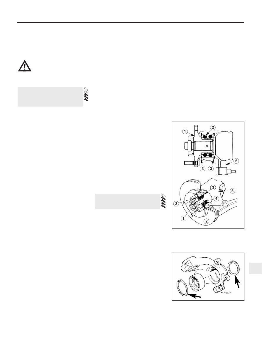
5 The hub must now be removed from the
bearing inner races. It is preferable to use a
press to do this, but it is possible to drive out
the hub using a length of metal tube of
suitable diameter (see illustration).
6 Part of the inner race will remain on the hub,
and this should be removed using a puller.
7 Note that if this procedure is being used to
renew the hub only (ie it is not intended to
renew the bearings), then it is important to
check the condition of the bearing balls and
races, to see if they are fit for re-use. It is
difficult to be sure that no damage has
occurred, especially if makeshift methods
have been used during removal; in practice, it
is probably false economy not to renew the
bearings in any case, having got this far.
8 Using circlip pliers, extract the inner and
outer circlips securing the hub bearing in the
steering knuckle (see illustration).
9 Press or drive out the bearing, using a
length of metal tubing of diameter slightly less
than the bearing outer race.
10 Clean the bearing seating faces in the
steering knuckle.
3 Front hub and bearings -
inspection and renewal
2 Steering knuckle and hub
assembly -
removal and refitting
Suspension and steering systems 10•5
10
3.5 Front hub and bearing
1 Hub
4 Stub axle
2 Double-row ball-bearing 5 Steering knuckle
3 Circlips
6 ABS sensor
3.8 Front wheel bearing retaining circlips
(arrowed)