Ford Mondeo (petrol engines). Manual - part 38
General information
1 This system consists of the pulse-air
solenoid valve, the pulse-air valve itself,
contained in the filter housing, and the piping
- see illustration 2.1A. It injects filtered air
directly into the exhaust ports, using the
pressure variations in the exhaust gases to
draw air through from the filter housing; air will
flow into the exhaust only when its pressure is
below atmospheric. The pulse-air valve can
allow gases to flow only one way, so there is
no risk of hot exhaust gases flowing back into
the filter.
2 The system’s primary function is raise
exhaust gas temperatures on start-up, thus
reducing the amount of time taken for the
oxygen sensor and catalytic converter to
reach operating temperature. Until this
happens, the system reduces emission of
unburned hydrocarbon particles (HC) and
carbon monoxide (CO) by ensuring that a
considerable proportion of these substances
remaining in the exhaust gases after
combustion are burned up, either in the
manifold itself or in the catalytic converter.
3 To ensure that the system does not upset
the smooth running of the engine under
normal driving conditions, it is linked by the
pulse-air solenoid valve to the ECU, so that it
only functions during engine warm-up, when
the oxygen sensor is not influencing the
fuel/air mixture ratio.
Checking
4 Poor idle, stalling, backfiring and poor
driveability can be caused by a fault in the
system.
5 Inspect the vacuum pipe/hose connected
between the filter housing and the solenoid
valve for kinks, leaks and cracks along its
entire length. Repair or renew as necessary.
6 Inspect the filter housing and piping. If
either is cracked or damaged, renew it.
7 If the pulse-air solenoid valve is thought to
be faulty, unplug its electrical connector and
disconnect its vacuum hoses. Connect a
battery directly across the valve terminals,
and check that air can flow through the valve
passages when the solenoid is thus
energised, and that nothing can pass when
the solenoid is not energised. Alternatively,
connect an ohmmeter to measure the
resistance across the valve terminals, and
compare this reading to the one listed in the
Specifications Section at the beginning of this
Chapter. Renew the solenoid valve if it is
faulty.
8 Further testing should be left to a dealer
service department.
Component renewal
Pulse-air solenoid valve
Note: This component can be identified by its
smaller top and its clip fastening. Do not
confuse it with the adjacent EGR solenoid
valve, especially when reconnecting vacuum
hoses.
9 Disconnect the battery negative (earth) lead
- see Section 1 of Chapter 5.
10 Remove the air mass meter and resonator
- refer to Chapter 4. If better access is
required, remove the plenum chamber also
(see illustration).
11 Releasing its wire clip, unplug the
electrical connector, then use a small
screwdriver to release the clip securing the
valve to the bulkhead mounting bracket.
Withdraw the valve, then label and disconnect
the two vacuum hoses.
12 Refitting is the reverse of the removal
procedure; ensure that the hoses are correctly
reconnected.
Pulse-air filter housing
Note: This component, and those around it,
will be very hot when the engine is running.
Always allow the engine to cool down fully
before starting work, to prevent the possibility
of burns.
13 Raise the front of the vehicle, and support
it securely on axle stands. Disconnect the
vacuum hose from the base of the filter
housing (see illustration).
14 Disconnect the battery negative (earth)
lead - see Section 1 of Chapter 5.
15 Unbolt the resonator support bracket
from the engine compartment front
crossmember, slacken the two clamp screws
securing the resonator to the air mass meter
and plenum chamber hoses, then swing the
resonator up clear of the thermostat housing
(see Chapter 4).
16 Remove the screws securing the filter
housing to the piping, unscrew the mounting
bolt, then withdraw the housing (see
illustration).
17 To dismantle the filter housing, undo the
four screws and separate the top from the
base of the housing; extract the foam filter,
and clean it in a suitable solvent (see
illustrations). If any of the housing’s
7 Pulse-air system -
general information
Emissions control systems 6•17
6
7.17A Remove four screws to release filter
housing top from base . . .
7.17B . . .and withdraw foam filter for
cleaning, if required - note valve in base of
housing
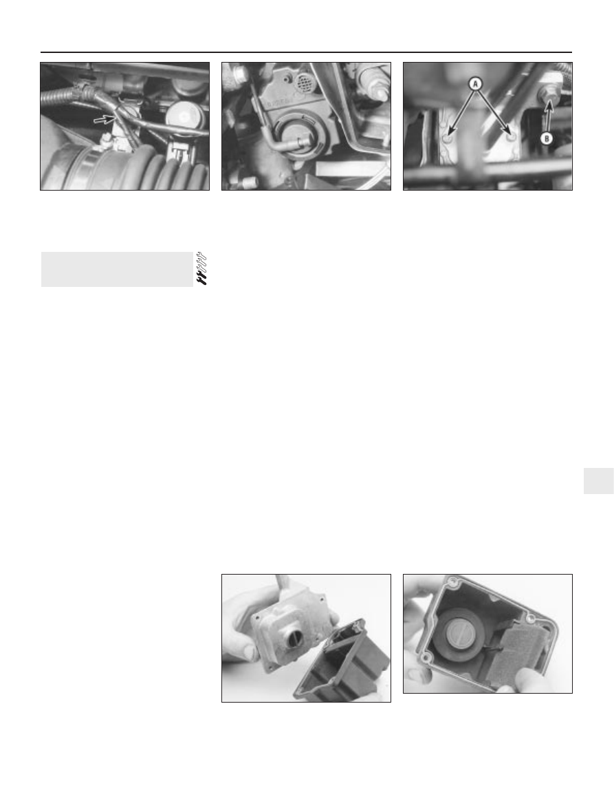
7.10 Pulse-air solenoid valve (arrowed) is
located on bulkhead mounting bracket. It
can be identified by its smaller top and its
clip fastening - do not confuse it with the
adjacent EGR solenoid valve
7.13 Disconnect vacuum hose from base
of pulse-air filter housing . . .
7.16 . . . undo screws “A” to disconnect
piping from housing, and mounting
bolt “B” to release housing