Ford Mondeo (petrol engines). Manual - part 15
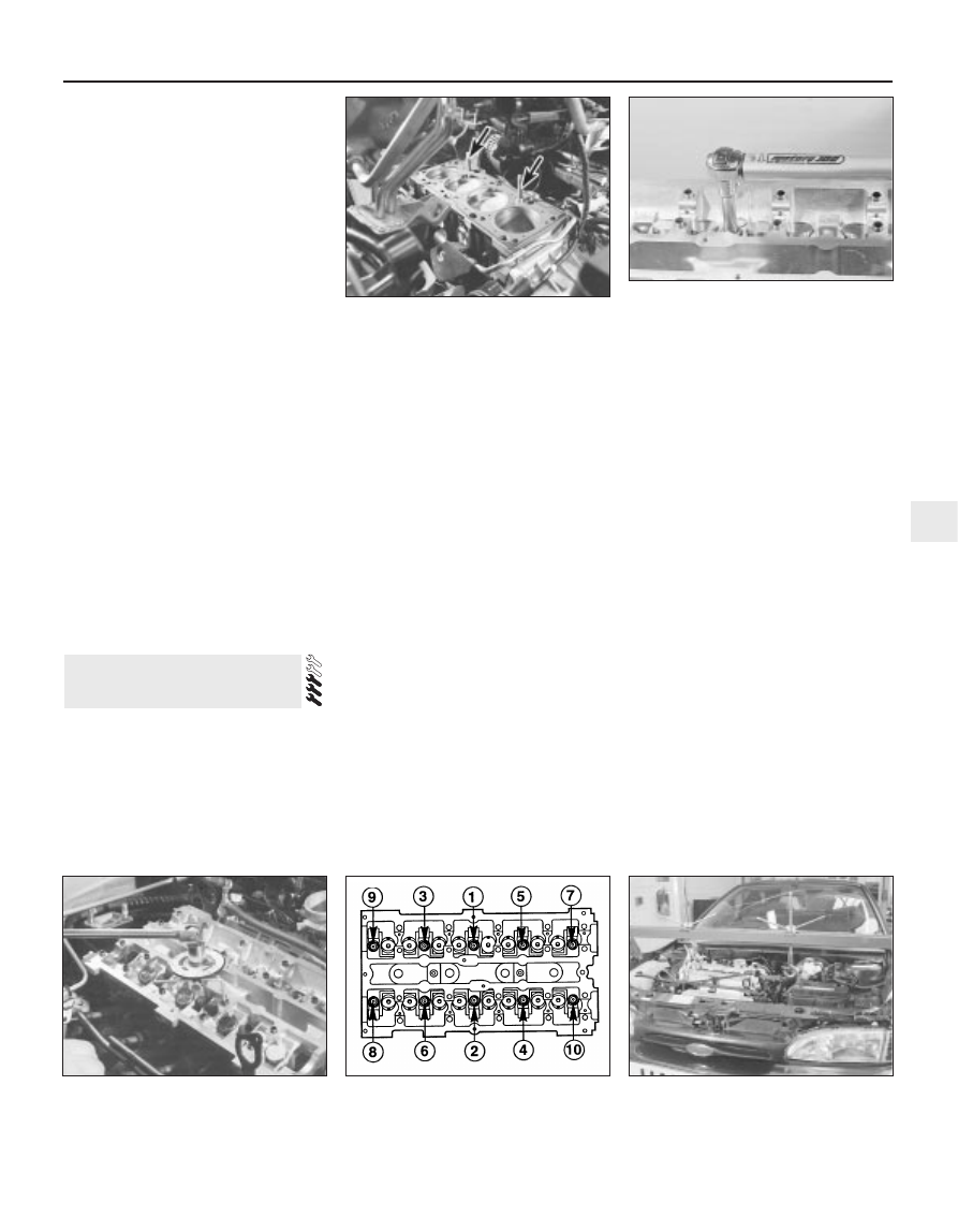
then an ordinary socket extension bar and an
angle gauge, to tighten the cylinder head
bolts in the stages given in the Specifications
Section of this Chapter (see illustrations).
Note: Once tightened correctly, following this
procedure, the cylinder head bolts do not
require check-tightening, and must not be re-
torqued.
33 Refit the hydraulic tappets (if removed),
the camshafts, their oil seals and pulleys (see
Sections 10, 11, 12 and 13, as appropriate).
Temporarily refit the crankshaft pulley, and
rotate the crankshaft clockwise to return the
pulley notches to the position described in
paragraph 8 of Section 10.
34 Refit the timing belt and covers, checking
the camshaft alignment (valve timing) and
setting the timing belt tension, as described in
Section 10.
35 The remainder of reassembly is the
reverse of the removal procedure, noting the
following points:
(a) Tighten all fasteners to the torque wrench
settings specified.
(b) When reassembling the
engine/transmission right-hand mounting,
renew the self-locking nuts, and do not
allow the mounting to twist as the middle
two of the bracket’s six nuts are
tightened.
(c) Refill the cooling system, and top-up the
engine oil.
(d) Check all disturbed joints for signs of oil
or coolant leakage, once the engine has
been restarted and warmed-up to normal
operating temperature.
Removal
Note: To carry out this task with the
engine/transmission installed in the vehicle
requires the assistance of at least one person,
plus the equipment necessary to raise and
support the front of the vehicle (high enough
that the sump can be withdrawn from
underneath), and to lift and support the
complete engine/transmission unit 2 to
3 inches from its mountings while the vehicle
is raised. Precise details of the procedure will
depend on the equipment available - the
following is typical.
The full procedure outlined below must be
followed, so that the mating surfaces can be
cleaned and prepared to achieve an oil-tight
joint on reassembly, and so that the sump
can be aligned correctly; depending on your
skill and experience, and the tools and
facilities available, it may be that this task can
be carried out only with the engine removed
from the vehicle.
Note that the sump gasket must be
renewed whenever it is disturbed.
1 With the vehicle parked on firm level
ground, open the bonnet and disconnect the
battery negative (earth) lead - see Chapter 5,
Section 1.
2 Drain the engine oil, then clean and refit the
engine oil drain plug, tightening it to the
specified torque wrench setting. Although not
strictly necessary as part of the dismantling
procedure, owners are advised to remove
and discard the oil filter, so that it can be
renewed with the oil (see Chapter 1).
3 Drain the cooling system (see Chapter 1).
4 Disconnect the radiator bottom hose from
the radiator union and from the (heater)
coolant pipe. Unbolt the coolant pipe from
the sump; if they will prevent sump removal,
disconnect or release the coolant hoses from
the oil cooler unions (where fitted).
5 Unscrew the two bolts securing the power
steering system pipes to the right-hand side
of the subframe.
6 Unplug the electrical connector(s) to
disconnect the oxygen sensor and, where
fitted, the oil level sensor wiring - unclip the
connectors to release the wiring where
necessary.
7 Where the vehicle is fitted with automatic
transmission, trace the fluid cooler lines from
the transmission to the radiator, and release
them from any clips etc, so that they have as
much movement as possible.
8 Remove the auxiliary drivebelt cover (see
Chapter 1).
9 Unscrew the nuts to disconnect the
exhaust system front downpipe from the
manifold, then either unhook all the system’s
rubber mountings and withdraw the complete
exhaust system from under the vehicle, or
remove only the downpipe/catalytic converter
(see Chapter 4 for details).
10 Unscrew the sump-to-transmission bolts,
also any securing the engine/transmission
lower adaptor plate.
11 Unplugging the two electrical connectors,
disconnecting the vacuum hose (where fitted)
and disconnecting the crankcase breather
hose from the cylinder head cover, remove
the complete air cleaner assembly with the air
mass meter, the resonator and the plenum
chamber (see Chapter 4).
12 Take the weight of the engine/
transmission unit using the lifting eyes
provided on the cylinder head; bolt on
15 Sump - removal and refitting
In-car engine repair procedures 2A•19
2A
14.32B . . . and to third stage using angle
gauge
14.32C Cylinder head bolt tightening
sequence
Note: View from rear of vehicle
15.12 Equipment must be available to raise
and support engine/transmission unit while
vehicle is raised, to allow sump removal
14.30 Refitting cylinder head - note
fabricated guide studs (arrowed)
14.32A Tightening cylinder head bolts (to
first and second stages) using torque
wrench . . .