Ford Mondeo (petrol engines). Manual - part 13
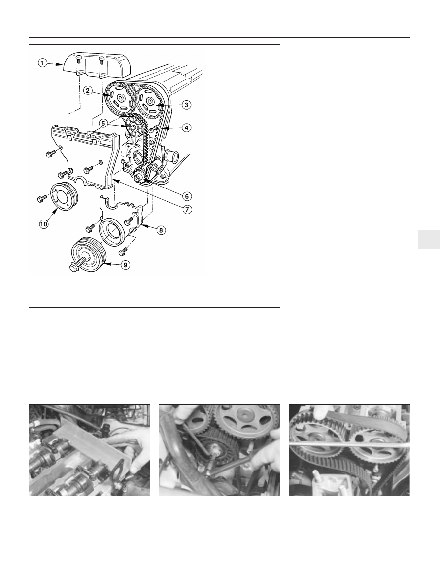
1 With the vehicle parked on firm level
ground, open the bonnet and disconnect the
battery negative (earth) lead - see Chapter 5,
Section 1 (see illustration).
2 Unbolt the power steering high-pressure
pipe from the cylinder head rear support
plate/engine lifting eye, and from the front
support plate/pump bracket.
3 Unscrew the six nuts securing the
engine/transmission right-hand mounting
bracket, then withdraw the bracket.
4 Slacken the water pump pulley bolts.
5 Remove the cylinder head cover (see
Section 5).
6 Remove the spark plugs, covering their
holes with clean rag, to prevent dirt or other
foreign bodies from dropping in (see Chap-
ter 1).
7 Remove the auxiliary drivebelt (see Chap-
ter 1).
8 Rotate the crankshaft clockwise until the
second pair of notches in the pulley rim align
with the edge of the sump mark, so that Nos
1 and 4 cylinders are at TDC (see Section 4).
9 Unbolt and remove the water pump pulley
and the auxiliary drivebelt idler pulley.
10 Obtain Ford service tool 21-162, or
fabricate a substitute from a strip of metal
5 mm thick (while the strip’s thickness is
critical, its length and width are not, but
should be approximately 180 to 230 mm by
20 to 30 mm). Check that Nos 1 and 4
cylinders are at Top Dead Centre (TDC) - No 1
on the compression stroke - by resting this
tool on the cylinder head mating surface, and
sliding it into the slot in the left-hand end of
both camshafts (see illustration). The tool
should slip snugly into both slots while resting
on the cylinder head mating surface; if one
camshaft is only slightly out of alignment, it is
permissible to use an open-ended spanner to
rotate the camshaft gently and carefully until
the tool will fit.
11 If both camshaft slots (they are machined
significantly off-centre) are below the level of
the cylinder head mating surface, rotate the
crankshaft through one full turn clockwise
and fit the tool again; it should now fit as
described in the previous paragraph.
12 With the camshaft aligning tool remaining
in place, remove the crankshaft pulley. Do not
use the locked camshafts to prevent the
crankshaft from rotating - use only the locking
methods described in Section 8.
13 Remove the timing belt lower and middle
covers (see Section 9).
14 With the camshaft aligning tool still in
place, slacken the tensioner bolt, and use an
Allen key inserted into its centre to rotate the
tensioner clockwise as far as possible away
from the belt; retighten the bolt to secure the
tensioner clear of the timing belt (see
illustration).
15 If the timing belt is to be re-used, use
white paint or similar to mark its direction of
rotation, and note from the manufacturer’s
markings which way round it is fitted.
Withdraw the belt (see illustration). Do not
rotate the crankshaft until the timing belt is
refitted.
16 If the belt is being removed for reasons
other than routine renewal, check it carefully
for any signs of uneven wear, splitting, cracks
(especially at the roots of the belt teeth) or
In-car engine repair procedures 2A•11
2A
10.10 Fit camshaft aligning tool to ensure
engine is locked with Nos 1 and 4 cylinders
at TDC
10.14 Slacken tensioner bolt, and use
Allen key to rotate tensioner away from
timing belt . . .
10.15 . . . then withdraw timing belt
10.1 Timing belt and cover details
1 Timing belt upper cover
2 Inlet camshaft toothed pulley
3 Exhaust camshaft toothed pulley
4 Timing belt
5 Timing belt tensioner
6 Crankshaft toothed pulley
7 Timing belt middle cover
8 Timing belt lower cover
9 Crankshaft pulley
10 Water pump pulley