Ford Mondeo (petrol engines). Manual - part 14
 

  Index      Ford     Ford Mondeo - service and repair manual (petrol engines)


Search            


Content   ..  12  13  14  15   ..


Ford Mondeo (petrol engines). Manual - part 14


wear (scoring, pitting etc) and for ovality, and
renew if necessary.
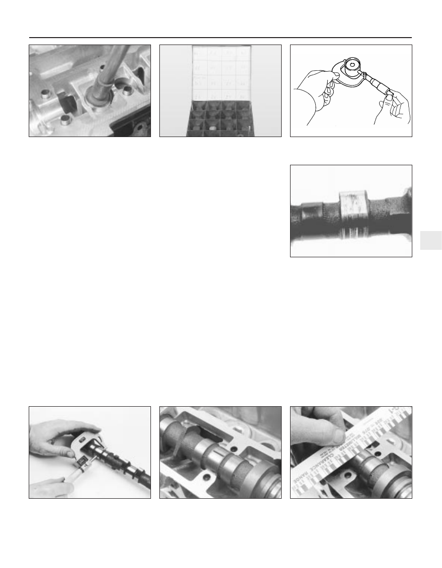
Measure the outside diameter of each
tappet (see illustration) - take measurements
at the top and bottom of each tappet, then a
second set at right-angles to the first; if any
measurement is significantly different from
the others, the tappet is tapered or oval (as
applicable) and must be renewed. If the
necessary equipment is available, measure
the inside diameter of the corresponding
cylinder head bore. Compare the
measurements obtained to those given in the
Specifications Section of this Chapter; if the
tappets or the cylinder head bores are
excessively worn, new tappets and/or a new
cylinder head will be required.
If the engine’s valve components have
sounded noisy, particularly if the noise
persists after initial start-up from cold, there is
reason to suspect a faulty hydraulic tappet.
Only a good mechanic experienced in these
engines can tell whether the noise level is
typical, or if renewal of one or more of the
tappets is warranted. If faulty tappets are
diagnosed, and the engine’s service history is
unknown, it is always worth trying the effect
of renewing the engine oil and filter (see
Chapter 1), using only good-quality engine oil
of the recommended viscosity and
specification, before going to the expense of
renewing any of the tappets - refer also to the
advice in Section 1 of this Chapter.

10 Visually examine the camshaft lobes for
score marks, pitting, galling (wear due to
rubbing) and evidence of overheating (blue,
discoloured areas). Look for flaking away of
the hardened surface layer of each lobe (see
illustration)
. If any such signs are evident,
renew the component concerned.
11 Examine the camshaft bearing journals
and the cylinder head bearing surfaces for
signs of obvious wear or pitting. If any such
signs are evident, renew the component
concerned.
12 Using a micrometer, measure the
diameter of each journal at several points
(see illustration). If the diameter of any one
journal is less than the specified value, renew
the camshaft.
13 To check the bearing journal running
clearance, remove the hydraulic tappets, use
a suitable solvent and a clean lint-free rag to
clean carefully all bearing surfaces, then refit
the camshafts and bearing caps with a strand
of Plastigage across each journal (see
illustration)
. Tighten the bearing cap bolts to
the specified torque wrench setting (do not
rotate the camshafts), then remove the
bearing caps and use the scale provided to
measure the width of the compressed strands
(see illustration). Scrape off the Plastigage
with your fingernail or the edge of a credit
card - don’t scratch or nick the journals or
bearing caps.
14 If the running clearance of any bearing is

found to be worn to beyond the specified
service limits, fit a new camshaft and repeat
the check; if the clearance is still excessive,
the cylinder head must be renewed.
15 To check camshaft endfloat, remove the
hydraulic tappets, clean the bearing surfaces
carefully, and refit the camshafts and bearing
caps. Tighten the bearing cap bolts to the
specified torque wrench setting, then
measure the endfloat using a DTI (Dial Test
Indicator, or dial gauge) mounted on the
cylinder head so that its tip bears on the
camshaft right-hand end.
16 Tap the camshaft fully towards the gauge,
zero the gauge, then tap the camshaft fully

In-car engine repair procedures  2A•15

2A

13.12  Measure each journal diameter with

a micrometer - if any journal measures less

than the specified limit, renew the camshaft

13.13A  Lay a strip of Plastigage on each

camshaft journal

13.13B  Compare the width of the crushed

Plastigage to the scale on the envelope to

determine the running clearance

13.6A  Removing hydraulic tappets

13.6B  Hydraulic tappets must be stored as

described in text

13.8  Use a micrometer to measure

diameter of hydraulic tappets

13.10  Check the cam lobes for pitting,

wear and score marks - if scoring is

excessive, as is the case here, renew the

camshaft

away from the gauge, and note the gauge
reading. If the endfloat measured is found to
be at or beyond the specified service limit, fit
a new camshaft and repeat the check; if the
clearance is still excessive, the cylinder head
must be renewed.

Refitting

17 On reassembly, liberally oil the cylinder
head hydraulic tappet bores and the tappets
(see illustration). Note that if new tappets are
being fitted, they must be charged with clean
engine oil before installation. Carefully refit the
tappets to the cylinder head, ensuring that each
tappet is refitted to its original bore, and is the
correct way up. Some care will be required to
enter the tappets squarely into their bores.
18 Liberally oil the camshaft bearings and
lobes (see illustration). Ensuring that each
camshaft is in its original location, refit the
camshafts, locating each so that the slot in its
left-hand end is approximately parallel to, and
just above, the cylinder head mating surface
(see illustration).
19 Ensure that the locating dowels are
pressed firmly into their recesses, and check
that all mating surfaces are completely clean,
unmarked and free from oil. Apply a thin film
of suitable sealant (Ford recommend Loctite
518) to the mating surfaces of each

camshaft’s right-hand bearing cap (see
illustration)
. Referring to paragraph 6 of
Section 12, some owners may wish to fit the
new camshaft oil seals at this stage.
20 All camshaft bearing caps have a single-
digit identifying number etched on them (see
illustration)
. The exhaust camshaft’s bearing
caps are numbered in sequence 0 (right-hand
cap) to 4 (left-hand cap), the inlet’s 5 (right-
hand cap) to 9 (left-hand cap); see illustration
13.21B for details. Each cap is to be fitted so
that its numbered side faces outwards, to the
front (exhaust) or to the rear (inlet).
21 Ensuring that each cap is kept square to
the cylinder head as it is tightened down, and
working in the sequence shown, tighten the
camshaft bearing cap bolts slowly and by one
turn at a time, until each cap touches the
cylinder head (see illustrations). Next, go
round again in the same sequence, tightening
the bolts to the first stage torque wrench
setting specified, then once more, tightening
them to the second stage setting. Work only
as described, to impose gradually and evenly
the pressure of the valve springs on the caps.
Fit the camshaft aligning tool; it should slip
into place as described in paragraph 10 of
Section 10 (see illustration).
22 Wipe off all surplus sealant, so that none
is left to find its way into any oilways. Follow
the sealant manufacturer’s manuals as to
the time needed for curing; usually, at least an
hour must be allowed between application of
the sealant and starting the engine.

2A•16 In-car engine repair procedures

13.17  Oil liberally when refitting hydraulic

tappets

13.18A  Apply engine assembly lubricant or

molybdenum disulphide-based grease to

the cam lobes and journals before refitting

a camshaft

13.19  Apply sealant to mating surface of

camshaft right-hand bearing caps

13.20  Etched marks on camshaft bearing

caps must be arranged as shown, and face

outwards

13.18B  Use camshaft position sensor lobe

to identify inlet camshaft on refitting -

locate camshafts as described in text

13.21A  Keep caps square to cylinder head

at all times when tightening down

13.21B  Camshaft bearing cap tightening

sequence

Note: View from front of vehicle - locate

bearing caps according to etched numbers,

aligned as described in text

13.21C  Fit camshaft aligning tool to set

TDC position . . .

23 If using Ford’s recommended procedure,
fit new oil seals to the camshafts as
described in paragraph 5 of Section 12.
24 Using the marks and notes made on
dismantling to ensure that each is refitted to
its original camshaft, refit the toothed pulleys
to the camshafts, tightening the retaining
bolts loosely (see illustration). Slip the timing
belt back onto the pulleys (refer to para-
graph 21 of Section 10) and tighten the bolts
securely - use the forked holding tool
described in paragraph 18 of Section 10.
25 The remainder of the reassembly
procedure, including checking the camshaft
alignment (valve timing) and setting the timing
belt tension, is as described in paragraphs 17
to 27 of Section 10.

Removal

Note: The following text assumes that the
cylinder head will be removed with both inlet
and exhaust manifolds attached; this
simplifies the procedure, but makes it a bulky
and heavy assembly to handle - an engine
hoist will be required, to prevent the risk of
injury, and to prevent damage to any delicate
components as the assembly is removed and
refitted. If it is wished first to remove the
manifolds, proceed as described in Sections
6 and 7 of this Chapter; amend the following
procedure accordingly.

Relieve the fuel system pressure (see
Chapter 4).
With the vehicle parked on firm level
ground, open the bonnet and disconnect the
battery negative (earth) lead - see Chapter 5,
Section 1.
Whenever you disconnect any vacuum
lines, coolant and emissions hoses, wiring
loom connectors, earth straps and fuel lines
as part of the following procedure, always
label them clearly, so that they can be
correctly reassembled.

Unplugging the two electrical connectors,
disconnecting the vacuum hose (where fitted)
and disconnecting the crankcase breather
hose from the cylinder head cover, remove
the complete air cleaner assembly with the air
mass meter, the resonator and the plenum
chamber (see Chapter 4).
Equalise the pressure in the fuel tank by
removing the filler cap, then undo the fuel
feed and return lines connecting the engine to
the chassis (see Chapter 4). Plug or cap all
open fittings.
Disconnect the accelerator cable from the
throttle linkage as described in Chapter 4 -

where fitted, disconnect also the cruise control
actuator cable (see Chapter 12). Secure the
cable(s) clear of the engine/transmission.
Unbolt the power steering high-pressure
pipe from the cylinder head rear support
plate/engine lifting eye, and from the front
support plate/pump bracket. Releasing its
wire clip, unplug the power steering pressure
switch electrical connector, then unbolt the
earth lead from the cylinder head rear support
plate/engine lifting eye.
Remove the three screws securing the
wiring “rail” to the rear of the manifold.
Releasing its wire clip, unplug the large
electrical connector (next to the fuel pressure
regulator) to disconnect the engine wiring from
the main loom (see illustration). Unplug the
electrical connectors on each side of the
ignition coil, and the single connector from
beneath the front of the thermostat housing, to
disconnect the coil and coolant temperature
gauge sender wiring (see illustration).
Marking or labelling them as they are
unplugged, disconnect the vacuum hoses as
follows:
(a) One from the rear of the throttle housing

(only the one hose - there is no need to
disconnect the second hose running to
the fuel pressure regulator).

(b) One from the union on the inlet manifold’s

left-hand end (see illustration).

(c) The braking system vacuum servo unit

hose (see Chapter 9 for details).

(d) Disconnect all vacuum hoses from the

Exhaust Gas Recirculation system
components - one from the EGR valve
and two from the EGR pipe. (Note that
these last two are of different sizes, as are
their pipe stubs, so that they can only be
connected the correct way round.)

10 Unbolt both parts of the exhaust manifold
heat shield; unclip the coolant hose to allow the
upper part to be withdrawn. Either remove the
dipstick and tube, or swing them out of the way.
11 Unscrew the single bolt securing the
pulse-air filter housing to the engine/
transmission front mounting bracket, then
disconnect its vacuum hose.
12 Drain the cooling system (see Chapter 1).
13 Disconnect all coolant hoses from the
thermostat housing (see illustration).

14 Cylinder head 

removal and refitting

In-car engine repair procedures  2A•17

2A

14.9  Disconnect vacuum hoses (arrowed)

as described in text

14.13  Disconnect all coolant hoses

(arrowed) from thermostat housing

13.24  . . . while camshaft toothed pulleys

are refitted

14.8A  Release wire clip to unplug engine

wiring loom connector from inlet manifold

14.8B  Unplug connectors (arrowed) to

disconnect ignition coil wiring

Masking tape and/or a touch-
up paint applicator work 
well for marking items. 
Take instant photos, or

sketch the locations of components
and brackets.

14 Unscrew the two nuts to disconnect the
exhaust system front downpipe from the
manifold (Chapter 4); disconnect the oxygen
sensor wiring, so that it is not strained by the
weight of the exhaust system.
15 Remove the auxiliary drivebelt (see
Chapter 1).
16 Support the weight of the
engine/transmission using a trolley jack, with
a wooden spacer to prevent damage to the
sump.
17 Unscrew the six nuts securing the
engine/transmission right-hand mounting
bracket, then withdraw the bracket. Unbolt
the auxiliary drivebelt’s idler pulley (see
illustration)
.
18 Unbolt the cylinder head front and rear
support plates (see illustrations).
19 Remove the timing belt and both
camshafts (see Sections 10 and 13); if the
cylinder head is to be dismantled, withdraw
the hydraulic tappets.
20 Remove the timing belt inner shield (see
Section 9).
21 Working in the reverse of the sequence
shown in illustration 14.32C, slacken the ten
cylinder head bolts progressively and by one
turn at a time; a Torx key (TX 55 size) will be
required. Remove each bolt in turn, and
ensure that new replacements are obtained
for reassembly; these bolts are subjected to
severe stresses and so must be renewed,
regardless of their apparent condition,
whenever they are disturbed.

22 Lift the cylinder head away; use
assistance if possible, as it is a heavy
assembly (see illustration). Remove the
gasket, noting the two dowels, and discard it.

Refitting

23 The mating faces of the cylinder head and
cylinder block must be perfectly clean before
refitting the head. Use a hard plastic or wood
scraper to remove all traces of gasket and
carbon; also clean the piston crowns. Take
particular care, as the soft aluminium alloy is
easily damaged. Also, make sure that the
carbon is not allowed to enter the oil and
water passages - this is particularly important
for the lubrication system, as carbon could
block the oil supply to any of the engine’s
components. Using adhesive tape and paper,
seal the water, oil and bolt holes in the
cylinder block. Clean all the pistons in the
same way.

24 Check the mating surfaces of the cylinder
block and the cylinder head for nicks, deep
scratches and other damage. If slight, they
may be removed carefully with a file, but if
excessive, machining may be the only
alternative to renewal.
25 If warpage of the cylinder head gasket
surface is suspected, use a straight edge to
check it for distortion. Refer to Part B of this
Chapter, Section 7, if necessary.
26 Wipe clean the mating surfaces of the
cylinder head and cylinder block. Check that
the two locating dowels are in position in the
cylinder block, and that all cylinder head bolt
holes are free from oil.
27 Position a new gasket over the dowels on
the cylinder block surface, so that the
“TOP/OBEN” mark is uppermost, and the
tooth (or teeth, according to engine size)
protruding from one edge point to the front of
the vehicle (see illustration).
28 Temporarily refit the crankshaft pulley,
and rotate the crankshaft anti-clockwise so
that No 1 cylinder’s piston is lowered to
approximately 20 mm before TDC, thus
avoiding any risk of valve/piston contact and
damage during reassembly.
29 As the cylinder head is such a heavy and
awkward assembly to refit with manifolds, it is
helpful to make up a pair of guide studs from
two 10 mm (thread size) studs approximately
90 mm long, with a screwdriver slot cut in one
end - two old cylinder head bolts with their
heads cut off would make a good starting
point. Screw these guide studs, screwdriver
slot upwards to permit removal, into the bolt
holes at diagonally-opposite corners of the
cylinder block surface (or into those where
the locating dowels are fitted, as shown);
ensure that approximately 70 mm of stud
protrudes above the gasket.
30 Refit the cylinder head, sliding it down the
guide studs (if used) and locating it on the
dowels (see illustration). Unscrew the guide
studs (if used) when the head is in place.
31 Fit the new cylinder head bolts dry (do not
oil 
their threads); carefully enter each into its
hole and screw it in, by hand only, until finger-
tight.
32 Working progressively and in the
sequence shown, use first a torque wrench,

2A•18 In-car engine repair procedures

14.17  Unbolt auxiliary drivebelt idler pulley

14 18A  Remove cylinder head front . . .

14.18B  . . . and rear support plates

14.22  Using an engine hoist to lift off the

cylinder head complete with manifolds

14.27  Ensuring protruding tooth (or teeth)

“A” are at front and marking “B” is

upwards, locate new cylinder head gasket

on dowels “C”

To prevent carbon entering
the gap between the pistons
and bores, smear a little
grease in the gap. After

cleaning each piston, use a small brush
to remove all traces of grease and
carbon from the gap, then wipe away
the remainder with a clean rag.


Content   ..  12  13  14  15   ..