Ford Mondeo (petrol engines). Manual - part 11
 

  Index      Ford     Ford Mondeo - service and repair manual (petrol engines)


Search            


Content   ..  9  10  11  12   ..


Ford Mondeo (petrol engines). Manual - part 11


Torque wrench settings (continued)

Nm

lbf ft

Engine/automatic transmission rear mounting:

Mounting bracket-to-transmission  . . . . . . . . . . . . . . . . . . . . . . . . . . .

48 to 49

35 to 36

Mounting-to-subframe bolts - stage 1  . . . . . . . . . . . . . . . . . . . . . . . .

10

7

Mounting-to-subframe bolts - stage 2  . . . . . . . . . . . . . . . . . . . . . . . .

48

35

Mounting centre bolt  . . . . . . . . . . . . . . . . . . . . . . . . . . . . . . . . . . . . . .

120

89

Engine/transmission left-hand mounting:

Bracket-to-transmission nuts  . . . . . . . . . . . . . . . . . . . . . . . . . . . . . . .

83

61

Mounting centre bolt  . . . . . . . . . . . . . . . . . . . . . . . . . . . . . . . . . . . . . .

Not available

Mounting-to-body bolts  . . . . . . . . . . . . . . . . . . . . . . . . . . . . . . . . . . .

Not available

Engine/transmission right-hand mounting:

Bracket-to-engine and mounting nuts  . . . . . . . . . . . . . . . . . . . . . . . .

83 to 90

61 to 66

Mounting-to-body bolts  . . . . . . . . . . . . . . . . . . . . . . . . . . . . . . . . . . .

84

62

Note: Refer to Part B of this Chapter for remaining torque wrench settings.

In-car engine repair procedures  2A•3

2A

How to use this Chapter

This Part of Chapter 2 is devoted to repair

procedures possible while the engine is still
installed in the vehicle, and includes only the
Specifications relevant to those procedures.
Since these procedures are based on the
assumption that the engine is installed in the
vehicle, if the engine has been removed from
the vehicle and mounted on a stand, some of
the preliminary dismantling steps outlined will
not apply.

Information concerning engine/transmission

removal and refitting, and engine overhaul, can
be found in Part B of this Chapter, which also
includes the Specifications relevant to those
procedures.

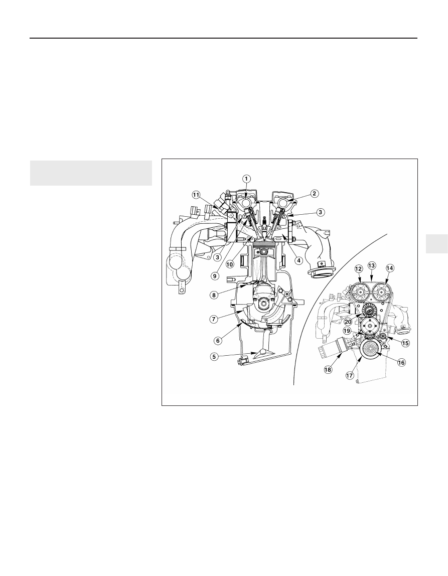
General description - engine

The engine, also known by Ford’s internal

code name “Zetec” (formerly “Zeta”), is of
four-cylinder, in-line type, mounted
transversely at the front of the vehicle, with
the (clutch and) transmission on its left-hand
end (see illustrations).

Apart from the plastic timing belt covers and

the cast-iron cylinder block/crankcase, all
major engine castings are of aluminium alloy.

The crankshaft runs in five main bearings,

the centre main bearing’s upper half
incorporating thrustwashers to control
crankshaft endfloat. The connecting rods
rotate on horizontally-split bearing shells at
their big-ends. The pistons are attached to the
connecting rods by gudgeon pins which are an
interference fit in the connecting rod small-end
eyes. The aluminium alloy pistons are fitted
with three piston rings: two compression rings
and an oil control ring. After manufacture, the
cylinder bores and piston skirts are measured
and classified into three grades, which must be
carefully matched together, to ensure the
correct piston/cylinder clearance; no oversizes
are available to permit reboring.

The inlet and exhaust valves are each

closed by coil springs; they operate in guides
which are shrink-fitted into the cylinder head,
as are the valve seat inserts.

Both camshafts are driven by the same

toothed timing belt, each operating eight
valves via self-adjusting hydraulic tappets,
thus eliminating the need for routine checking
and adjustment of the valve clearances. Each
camshaft rotates in five bearings that are line-

bored directly in the cylinder head and the
(bolted-on) bearing caps; this means that the
bearing caps are not available separately
from the cylinder head, and must not be
interchanged with caps from another engine.

The water pump is bolted to the right-hand

1 General information

1.3A  Longitudinal cross-section through engine - inset showing timing belt details

1  Inlet camshaft
2  Exhaust camshaft
3  Oil galleries
4  Exhaust port
5  Oil strainer and pick-up  pipe
6  Oil baffle
7  Crankshaft
8  Piston-cooling oil jet (where 

fitted)

9  Inlet valve

10  Inlet port
11  Fuel injector
12  Inlet camshaft toothed 

pulley

13  Timing belt
14  Exhaust camshaft toothed 

pulley

15  Timing belt (front) guide 

pulley

16  Crankshaft toothed pulley 

- behind

17  Crankshaft pulley
18  Oil cooler (where fitted)
19  Timing belt (rear) guide 

pulley

20  Timing belt tensioner

end of the cylinder block, inboard of the
timing belt, and is driven with the power
steering pump and alternator by a flat
“polyvee”-type auxiliary drivebelt from the
crankshaft pulley.

When working on this engine, note that

Torx-type (both male and female heads) and
hexagon socket (Allen head) fasteners are
widely used; a good selection of bits, with the
necessary adaptors, will be required, so that
these can be unscrewed without damage
and, on reassembly, tightened to the torque
wrench settings specified.

General description - lubrication
system

Lubrication is by means of an eccentric-

rotor trochoidal pump, which is mounted on
the crankshaft right-hand end, and draws oil
through a strainer located in the sump. The
pump forces oil through an externally-
mounted full-flow cartridge-type filter - on
some versions of the engine, an oil cooler is
fitted to the oil filter mounting, so that clean
oil entering the engine’s galleries is cooled by
the main engine cooling system. From the
filter, the oil is pumped into a main gallery in
the cylinder block/crankcase, from where it is
distributed to the crankshaft (main bearings)
and cylinder head (see illustration).

The big-end bearings are supplied with oil

via internal drillings in the crankshaft. On
some versions of the engine, each piston
crown is cooled by a spray of oil directed at
its underside by a jet. These jets are fed by
passages off the crankshaft oil supply
galleries, with spring-loaded valves to ensure
that the jets open only when there is sufficient
pressure to guarantee a good oil supply to
the rest of the engine components; where the
jets are not fitted, separate blanking plugs are
provided, so that the passages are sealed,
but can be cleaned at overhaul (see
illustration)
.

2A•4 In-car engine repair procedures

1.3B  Lateral cross-section through engine

1  Exhaust valve
2  Piston
3  Oil baffle

4  Oil strainer and pick-up 

pipe

5  Spark plug

6  Fuel injector
7  Piston-cooling oil jets 

(where fitted)

1.10  Engine lubrication system - inset showing longitudinal cross-section

1  Main oil gallery
2  From oil filter
3  Oil pump
4  Cylinder head oil-retaining valve
5  Cylinder head oil gallery

6  Cylinder head oil supply
7  Oil return
8  Piston-cooling oil spray (where fitted)
9  Oil filter - oil cooler not shown here

1.11  Piston-cooling oil jet details

1  Oil jets (when fitted)
2  Oil flow - only when valve opens at set 

pressure

3  Oil spray
4  Blanking plug (when fitted)

The cylinder head is provided with two oil

galleries, one on the inlet side and one on the
exhaust, to ensure constant oil supply to the
camshaft bearings and hydraulic tappets. A
retaining valve (inserted into the cylinder
head’s top surface, in the middle, on the inlet
side) prevents these galleries from being
drained when the engine is switched off. The
valve incorporates a ventilation hole in its
upper end, to allow air bubbles to escape
from the system when the engine is restarted.

While the crankshaft and camshaft

bearings and the hydraulic tappets receive a
pressurised supply, the camshaft lobes and
valves are lubricated by splash, as are all
other engine components.

Valve clearances - general

It is necessary for a clearance to exist

between the tip of each valve stem and the
valve operating mechanism, to allow for the
expansion of the various components as the
engine reaches normal operating
temperature.

On most older engine designs, this meant

that the valve clearances (also known as
“tappet” clearances) had to be checked and
adjusted regularly. If the clearances were
allowed to be too slack, the engine would be
very noisy, its power output would suffer, and
its fuel consumption would increase. If the
clearances were allowed to be too tight, the
engine’s power output would be reduced,
and the valves and their seats could be
severely damaged.

The engines covered in this manual,

however, employ hydraulic tappets which use
the lubricating system’s oil pressure
automatically to take up the clearance
between each camshaft lobe and its
respective valve stem. Therefore, there is no
need for regular checking and adjustment of
the valve clearances, but it is essential that
only good-quality oil of the recommended
viscosity and specification is used in the
engine, and that this oil is always changed at
the recommended intervals. If this advice is
not followed, the oilways and tappets may
become clogged with particles of dirt, or
deposits of burnt (inferior) engine oil, so that
the system cannot work properly; ultimately,
one or more of the tappets may fail, and
expensive repairs may be required.

On starting the engine from cold, there will

be a slight delay while full oil pressure builds
up in all parts of the engine, especially in the
tappets; the valve components, therefore,
may well “rattle” for about 10 seconds or so,
and then quieten. This is a normal state of
affairs, and is nothing to worry about,
provided that all tappets quieten quickly and
stay quiet.

After the vehicle has been standing for

several days, the valve components may
“rattle” for longer than usual, as nearly all the
oil will have drained away from the engine’s
top end components and bearing surfaces.
While this is only to be expected, care must

be taken not to damage the engine under
these circumstances - avoid high speed
running until all the tappets are refilled with oil
and operating normally. With the vehicle
stationary, hold the engine at no more than a
fast idle speed (maximum 2000 to 2500 rpm)
for 10 to 15 seconds, or until the noise
ceases. Do not run the engine at more than
3000 rpm until the tappets are fully recharged
with oil and the noise has ceased.

If the valve components are thought to be

noisy, or if a light rattle persists from the top
end after the engine has warmed up to
normal operating temperature, take the
vehicle to a Ford dealer for expert advice.
Depending on the mileage covered and the
usage to which each vehicle has been put,
some vehicles may be noisier than others;
only a good mechanic experienced in these
engines can tell if the noise level is typical for
the vehicle’s mileage, or if a genuine fault
exists. If any tappet’s operation is faulty, it
must be renewed (Section 13).

The following major repair operations can

be accomplished without removing the
engine from the vehicle. However, owners
should note that any operation involving the
removal of the sump requires careful
forethought, depending on the level of skill
and the tools and facilities available; refer to
the relevant text for details.
(a) Compression pressure - testing.
(b) Cylinder head cover - removal and

refitting.

(c) Timing belt covers - removal and refitting.
(d) Timing belt - renewal.
(e) Timing belt tensioner and toothed pulleys

- removal and refitting.

(f)

Camshaft oil seals - renewal.

(g) Camshafts and hydraulic tappets -

removal and refitting.

(h) Cylinder head - removal, overhaul and

refitting.

(i)

Cylinder head and pistons -
decarbonising.

(j)

Sump - removal and refitting.

(k) Crankshaft oil seals - renewal.
(l)

Oil pump - removal and refitting.

(m) Piston/connecting rod assemblies -

removal and refitting (but see note below).

(n) Flywheel/driveplate - removal and

refitting.

(o) Engine/transmission mountings - removal

and refitting.

Clean the engine compartment and the

exterior of the engine with some type of
degreaser before any work is done. It will
make the job easier, and will help to keep dirt
out of the internal areas of the engine.

Depending on the components involved, it

may be helpful to remove the bonnet, to
improve access to the engine as repairs are
performed (refer to Chapter 11 if necessary).

Cover the wings to prevent damage to the
paint; special covers are available, but an old
bedspread or blanket will also work.

If vacuum, exhaust, oil or coolant leaks

develop, indicating a need for component/
gasket or seal replacement, the repairs can
generally be made with the engine in the
vehicle. The intake and exhaust manifold
gaskets, sump gasket, crankshaft oil seals
and cylinder head gasket are all accessible
with the engine in place.

Exterior components such as the intake

and exhaust manifolds, the sump, the oil
pump, the water pump, the starter motor, the
alternator and the fuel system components
can be removed for repair with the engine in
place.

Since the cylinder head can be removed

without lifting out the engine, camshaft and
valve component servicing can also be
accomplished with the engine in the vehicle,
as can renewal of the timing belt and toothed
pulleys.

In extreme cases caused by a lack of

necessary equipment, repair or renewal of
piston rings, pistons, connecting rods and
big-end bearings is possible with the engine
in the vehicle. However, this practice is not
recommended, because of the cleaning and
preparation work that must be done to the
components involved, and because of the
amount of preliminary dismantling work
required - these operations are therefore
covered in Part B of this Chapter.

When engine performance is down, or if
misfiring occurs which cannot be attributed to
the ignition or fuel systems, a compression
test can provide diagnostic clues as to the
engine’s condition. If the test is performed
regularly, it can give warning of trouble before
any other symptoms become apparent.
The engine must be fully warmed-up to
normal operating temperature, the oil level
must be correct, the battery must be fully
charged, and the spark plugs must be
removed. The aid of an assistant will be
required also.
Disable the ignition system by unplugging
the ignition coil’s electrical connector, and
remove fuse 14 to disconnect the fuel pump.
Fit a compression tester to the No 1
cylinder spark plug hole - the type of tester
which screws into the plug thread is to be
preferred.
Have the assistant hold the throttle wide
open and crank the engine on the starter
motor; after one or two revolutions, the
compression pressure should build up to a
maximum figure, and then stabilise. Record
the highest reading obtained.
Repeat the test on the remaining cylinders,
recording the pressure developed in each.
At the time of writing, no compression

3 Compression test 

description and interpretation

2 Repair operations possible with

the engine in the vehicle

In-car engine repair procedures  2A•5

2A

specifications were available from Ford, but a
typical reading would be in excess of 12 bars.
All cylinders should produce very similar
pressures; any difference greater than 10%
indicates the existence of a fault. Note that the
compression should build up quickly in a
healthy engine; low compression on the first
stroke, followed by gradually-increasing
pressure on successive strokes, indicates worn
piston rings. A low compression reading on the
first stroke, which does not build up during
successive strokes, indicates leaking valves or a
blown head gasket (a cracked head could also
be the cause). Deposits on the undersides of the
valve heads can also cause low compression.
If the pressure in any cylinder is
considerably lower than the others, introduce
a teaspoonful of clean oil into that cylinder
through its spark plug hole, and repeat the
test.
If the addition of oil temporarily improves
the compression pressure, this indicates that
bore or piston wear is responsible for the
pressure loss. No improvement suggests that
leaking or burnt valves, or a blown head
gasket, may be to blame.
10 A low reading from two adjacent cylinders
is almost certainly due to the head gasket
having blown between them; the presence of
coolant in the engine oil will confirm this.
11 If one cylinder is about 20 percent lower
than the others and the engine has a slightly
rough idle, a worn camshaft lobe or faulty
hydraulic tappet could be the cause.
12 If the compression is unusually high, the
combustion chambers are probably coated
with carbon deposits. If this is the case, the
cylinder head should be removed and
decarbonised.
13 On completion of the test, refit the spark
plugs, then reconnect the ignition system and
fuel pump.

General

Top Dead Centre (TDC) is the highest point
in its travel up-and-down its cylinder bore
that each piston reaches as the crankshaft

rotates. While each piston reaches TDC both
at the top of the compression stroke and
again at the top of the exhaust stroke, for the
purpose of timing the engine, TDC refers to
the piston position (usually No 1 piston) at the
top of its compression stroke.
It is useful for several servicing procedures
to be able to position the engine at TDC.
No 1 piston and cylinder are at the right-
hand (timing belt) end of the engine (right-
and left-hand are always quoted as seen from
the driver’s seat). Note that the crankshaft
rotates clockwise when viewed from the
right-hand side of the vehicle.

Locating TDC

Remove all the spark plugs (Chapter 1).
Disconnect both battery leads - see
Chapter 5, Section 1 - unless the starter
motor is to be used to turn the engine.
Apply the handbrake and ensure that the
transmission is in neutral, then jack up the
front right-hand side of the vehicle and
support on an axle stand. Remove the
roadwheel.
Remove the auxiliary drivebelt cover (see
Chapter 1) to expose the crankshaft pulley
and timing marks.
It is best to rotate the crankshaft using a
spanner applied to the crankshaft pulley bolt;
however, it is possible also to use the starter
motor (switched on either by an assistant
using the ignition key, or by using a remote
starter switch) to bring the engine close to
TDC, then finish with a spanner. If the starter
is used, be sure to disconnect the battery
leads immediately it is no longer required.
Note the two pairs of notches in the inner
and outer rims of the crankshaft pulley. In the
normal direction of crankshaft rotation
(clockwise, seen from the right-hand side of the
vehicle) the first pair of notches are irrelevant to
the vehicles covered in this manual, while the
second pair indicate TDC when aligned with
the rear edge of the raised mark on the sump.
Rotate the crankshaft clockwise until the
second pair of notches align with the edge of
the sump mark; use a straight edge extended
out from the sump if greater accuracy is
required (see illustrations).

10 Nos 1 and 4 cylinders are now at TDC,
one of them on the compression stroke.
Remove the oil filler cap; if No 4 cylinder
exhaust cam lobe is pointing to the rear of the
vehicle and slightly downwards, it is No 1
cylinder that is correctly positioned. If the
lobe is pointing horizontally forwards, rotate
the crankshaft one full turn (360°) clockwise
until the pulley notches align again, and the
lobe is pointing to the rear and slightly down.
No 1 cylinder will then be at TDC on the
compression stroke.
11 Once No 1 cylinder has been positioned
at TDC on the compression stroke, TDC for
any of the other cylinders can then be located
by rotating the crankshaft clockwise 180° at a
time and following the firing order (see
Specifications).
12 An alternative method of locating TDC is
to remove the cylinder head cover (see
Section 5) and to rotate the crankshaft
(clockwise, as described in paragraph 8
above) until the inlet valves for the cylinder
concerned have opened and just closed
again. Insert a length of wooden dowel
(approximately 150 mm/6 in long) or similar
into the spark plug hole until it rests on the
piston crown, and slowly further rotate the
crankshaft (taking care not to allow the dowel
to be trapped in the cylinder) until the dowel
stops rising - the piston is now at the top of
its compression stroke, and the dowel can be
removed.
13 There is a “dead” area around TDC (as
the piston stops rising, pauses and then
begins to descend) which makes difficult the
exact location of TDC by this method; if
accuracy is required, either establish carefully
the exact mid-point of the dead area, or refer
to the timing marks (paragraph 9 above).

Unplug the two electrical connectors and
disconnect the vacuum hose (where fitted),
then remove the air cleaner assembly cover
with the air mass meter, the resonator and the
plenum chamber (see Chapter 4).
Disconnect the accelerator cable from the

5 Cylinder head cover -

removal and refitting

4 Top Dead Centre (TDC) for 

No 1 piston - locating

2A•6 In-car engine repair procedures

4.9A  Do not use crankshaft pulley’s first

pair of notches “A” - align second pair of

notches “B” with raised rib on sump “C” . . .

4.9B  . . . using a straight edge extended

out from the sump (arrowed) if greater

accuracy is required

5.4  Disconnecting crankcase breather

hose from cylinder head cover union


Content   ..  9  10  11  12   ..