Ford Orion. Manual - part 63
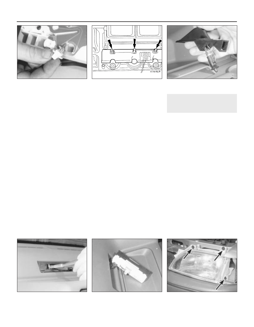
8 Turn the bulbholder a quarter-turn to align
the shoulders with the slots, then remove it
and pull the capless bulb from the bulbholder
(see illustration).
9 Fit the new bulb in reverse order.
Heater control panel
illumination
10 Undo the two retaining screws from its
upper edge, and withdraw the instrument
panel surround.
11 Pull free the heater control knobs, then
undo the heater control panel retaining
screws. Withdraw the panel from the facia just
enough to gain access to the bulbs on its rear
face (see illustration).
12 Twist the bulbs anti-clockwise to remove
them.
13 Refit in the reverse order of removal, and
check for satisfactory operation on
completion.
Automatic transmission selector
illumination
14 Prise out the lever quadrant cover (taking
care not to scratch the console), then pull the
bulbholder from under the selector lever
position indicator, untwist and remove the
bulb from the holder.
15 Fit the new bulb in the reverse order of
removal.
Glovebox light
16 Open the glovebox, then undo the two
retaining screws and withdraw the light/switch
unit.
17 Prise free the switch/bulbholder, then
untwist and remove the bulb from the holder
(see illustration).
18 Fit the new bulb using a reversal of the
removal procedure.
Hazard warning light tell-tale
19 Pull free the cover from the switch, then
pull free the bulb from the switch/holder.
20 Refit in the reverse order of removal, and
check for satisfactory operation.
Clock illumination
21 Engage the hooked ends of a pair of
circlip pliers in the two holes in the underside
of the clock bezel as shown, and carefully pull
free the clock from its aperture in the facia.
The bulbholder can then be untwisted and
withdrawn from the rear face of the clock and
the bulb renewed (see illustrations).
22 Refit in the reverse order of removal.
Cigar lighter illumination
23 Remove the lighter (Section 12), then
withdraw the illumination ring from the facia.
Remove the bulb from the illumination ring.
24 Refit in the reverse order of removal.
Check for satisfactory operation on
completion.
7
Exterior light units -
removal and refitting
2
1 Disconnect the battery negative (earth) lead
(refer to Chapter 5, Section 1), before
removing any of the light units.
Headlight
2 Open and support the bonnet, then on pre-
1993 models, undo the four retaining screws
along the top edge of the grille panel, and lift
the panel clear. On 1993-on XR3i models,
undo the four screws, release the two clips
and remove the plastic support bracket above
the radiator.
3 Remove the front indicator as described
later in this Section.
4 Detach the wiring connections from the
headlight and sidelight in the rear of the
appropriate headlight unit.
5 Working through the cut-out of the direction
indicator, unscrew the headlight lower
retaining screw, then undo the two upper
securing screws from the points indicated
(see illustration). On later models, there is an
additional upper retaining screw. Withdraw
the headlight forwards from the vehicle.
6 If a new headlight is to be fitted, remove the
headlight and sidelight bulbs/holders, and
transfer them to the new light unit as
described in Section 5. The individual parts of
the headlight are not otherwise renewable.
12•10 Body electrical system
7.5 Headlight unit retaining screws
(arrowed)
6.21B . . . for access to the bulbholder
6.21A Pull free the clock from the facia . . .
6.17 Glovebox light switch/bulbholder
removal
6.11 Heater control panel illumination bulb
locations (arrowed)
6.8 Bulbholder removal from the
instrument panel