Ford Orion. Manual - part 62
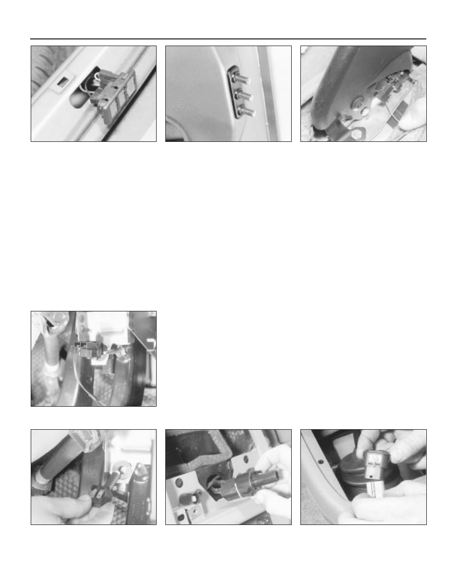
22 Disconnect the wiring connectors and
remove the switch (see illustration).
23 Refit in the reverse order of removal.
Rear wiper contact switch
24 Disconnect the battery negative (earth)
lead (refer to Chapter 5, Section 1).
25 Open the tailgate and remove its inner
trim panel.
26 Working through the access aperture in
the tailgate, use a thin-bladed screwdriver to
depress the switch retaining clips and extract
the switch from the panel (see illustration).
27 Disconnect the wiring connectors and
remove the switch.
28 Refit in the reverse order of removal.
Make sure that the pins and their contacts are
clean. On completion, check the operation of
the rear wipers, courtesy light, heated rear
window and the tailgate release/central
locking system.
Handbrake warning light switch
29 Disconnect the battery negative (earth)
lead (refer to Chapter 5, Section 1).
30 Refer to Chapter 11 for details, and
remove the front passenger (left-hand) seat
and the centre console.
31 Detach the wiring connector from the
handbrake warning light switch, then undo the
two retaining screws and remove the switch
(see illustration).
32 Refit in the reverse order of removal.
Check that the switch operates in a
satisfactory manner before refitting the
console and seat.
Brake stop-light switch
33 Disconnect the battery negative (earth)
lead (refer to Chapter 5, Section 1).
34 The brake stop-light switch is attached to
the brake pedal mounting bracket (see
illustration).
35 Detach the wiring connector from the
switch, then twist the switch through a quarter
of a turn (90º) and withdraw it from the
bracket (see illustration).
36 Refit in the reverse order of removal.
Ensure that the neck of the switch is against
the pedal before turning the switch 90º to
secure it.
37 Check that the switch operates in a
satisfactory manner to complete. The switch
should not operate during the first 2 mm of
pedal travel, but must operate within 20 mm of
pedal travel. If necessary, adjustment can be
made by removing the switch from the bracket
and turning the adjuster nut as required.
Heater/blower motor switch
38 Disconnect the battery negative (earth)
lead (refer to Chapter 5, Section 1).
39 Pull free and remove the heater control
knobs.
40 Unscrew and remove the two instrument
bezel retaining screws, and remove the bezel.
41 Undo the four retaining screws, and
remove the heater panel facia. Detach the
wiring connector to the heater panel
illumination bulb.
42 Compress the switch tabs to pull free the
switch, then detach the wiring multi-plug from
the switch (see illustration).
43 Refit in the reverse order of removal.
Electric window switches
44 Disconnect the battery negative (earth)
lead (refer to Chapter 5, Section 1).
45 Insert a thin-bladed screwdriver between
the switch and the console, then carefully
prise free the switch from its location. If the
switch is reluctant to release, do not apply
excessive force; remove the centre console
(see Chapter 11 for details) and release the
switch from the underside.
46 Detach the wire connector from the
switch, and remove it (see illustration).
47 Refit in the reverse order of removal, then
check the switch for satisfactory operation.
12•6 Body electrical system
4.46 Electric window switch removal
4.42 Heater blower motor switch removal
4.35 Brake stop-light switch removal
4.34 Brake stop-light switch location
4.31 Handbrake warning light switch
4.26 Contact switch unit in the tailgate
4.22 Luggage area contact switch removal
from the rear panel