Ford Orion. Manual - part 46
1
General information and
precautions
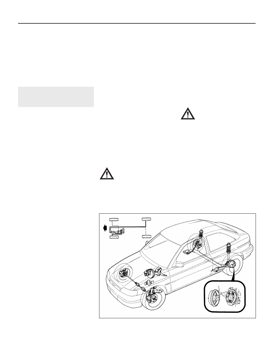
The braking system is of the diagonally
split, dual-circuit hydraulic type, with servo
assistance to the front disc brakes and rear
drum/disc brakes (see illustration). The dual-
circuit hydraulic system is a safety feature - in
the event of a malfunction somewhere in one
of the hydraulic circuits, the other circuit
continues to operate, providing at least some
braking effort. Under normal circumstances,
both brake circuits operate in unison, to
provide efficient braking.
The master cylinder (and the vacuum servo
unit to which it is bolted) is located on the left-
hand side of the bulkhead in the engine
compartment. On all right-hand drive variants,
they are jointly operated via a transverse
cross-link from the brake pedal.
Brake pressure control valves are fitted in-
line to each rear brake circuit, their function
being to regulate the braking force available at
each rear wheel, reducing the possibility of
the rear wheels locking up under heavy
braking. Van models also have a “light-laden”
valve incorporated into the rear braking
circuits for the same reason.
The front brake discs are of the ventilated
type on all 1.6 litre, 1.8 litre and ABS-
equipped models. Solid discs are fitted on all
other models. The front brake calipers are of
single sliding piston design, which ensures
that equal effort is applied through each pair
of brake pads to the discs. The calipers are
mounted on the front spindle carriers each
side.
Each rear brake drum can be simply
unbolted from its rear axle flange, together
with the integrally-fitted wheel hub, and
removed to provide unhindered access to the
shoe assemblies. Each rear brake shoe
assembly is operated by a twin-piston wheel
cylinder. The leading brake shoe in each
brake unit has a thicker lining than the trailing
shoe, so that they wear proportionally. To take
up the brake adjustment as the linings wear,
each rear brake assembly incorporates an
automatic adjuster mechanism.
On models fitted with rear disc brakes, the
brake calipers are of twin-piston fixed type,
with handbrake operation by means of
separate handbrake shoes operating within a
“drum-in-disc” arrangement.
The cable-operated handbrake acts on
both rear brakes, to provide an independent
means of brake operation.
An anti-lock braking system (ABS) is
available on some models, and has many of
the components in common with the
conventional braking system. Further details
on ABS can be found later in this Chapter.
Precautions
When servicing any part of the system,
work carefully and methodically; also observe
scrupulous cleanliness when overhauling any
part of the hydraulic system. Use only genuine
Ford replacement parts, or at least those of
known good quality.
Warning: Brake components
MUST be renewed as axle sets -
NEVER renew components on
only one wheel, as uneven
braking may result. Dust created by wear
of brake pads/shoes may contain
asbestos, which is a health hazard. Never
blow it out with compressed air, and do
not inhale any of it. DO NOT use
petroleum-based solvents to clean brake
parts - use brake cleaner or methylated
spirit only. DO NOT allow any brake fluid,
oil or grease to contact the brake friction
surfaces.
Warning: Hydraulic fluid is
poisonous; wash off immediately
and thoroughly in the case of
skin contact, and seek immediate
medical advice if any fluid is swallowed or
gets into the eyes. Certain types of
hydraulic fluid are inflammable, and may
ignite when allowed into contact with hot
components; when servicing the hydraulic
system, it is safest to assume that the fluid
IS inflammable, and to take precautions
against the risk of fire as though it is petrol
that is being handled. Hydraulic fluid is
also an effective paint stripper, and will
attack plastics; if any is spilt, it should be
washed off immediately, using copious
quantities of fresh water. Finally, it is
hygroscopic (it absorbs moisture from the
air) - old fluid may be contaminated and
unfit for further use. When topping-up or
renewing the fluid, always use the
recommended type, and ensure that it
comes from a freshly-opened sealed
container.
Torque wrench settings
Nm
lbf ft
Master cylinder to servo . . . . . . . . . . . . . . . . . . . . . . . . . . . . . . . . . . . . .
20 to 25
15 to 18
Servo unit to bracket/bulkhead . . . . . . . . . . . . . . . . . . . . . . . . . . . . . . .
35 to 45
26 to 33
Drum/hub to rear axle flange . . . . . . . . . . . . . . . . . . . . . . . . . . . . . . . . .
56 to 76
41 to 56
Caliper anchor bracket to spindle carrier . . . . . . . . . . . . . . . . . . . . . . . .
50 to 66
37 to 49
Caliper piston housing to anchor bracket:
Bendix caliper . . . . . . . . . . . . . . . . . . . . . . . . . . . . . . . . . . . . . . . . . . .
45 to 55
33 to 41
Teves caliper . . . . . . . . . . . . . . . . . . . . . . . . . . . . . . . . . . . . . . . . . . . .
20 to 25
15 to 18
Rear caliper mounting bolts . . . . . . . . . . . . . . . . . . . . . . . . . . . . . . . . . .
50 to 66
37 to 49
ABS hydraulic unit to bracket . . . . . . . . . . . . . . . . . . . . . . . . . . . . . . . . .
21 to 25
15 to 18
Roadwheel nuts . . . . . . . . . . . . . . . . . . . . . . . . . . . . . . . . . . . . . . . . . . .
70 to 100
52 to 74
9•2 Braking system
1.1 Standard braking system layout and principal components