Ford Orion. Manual - part 45
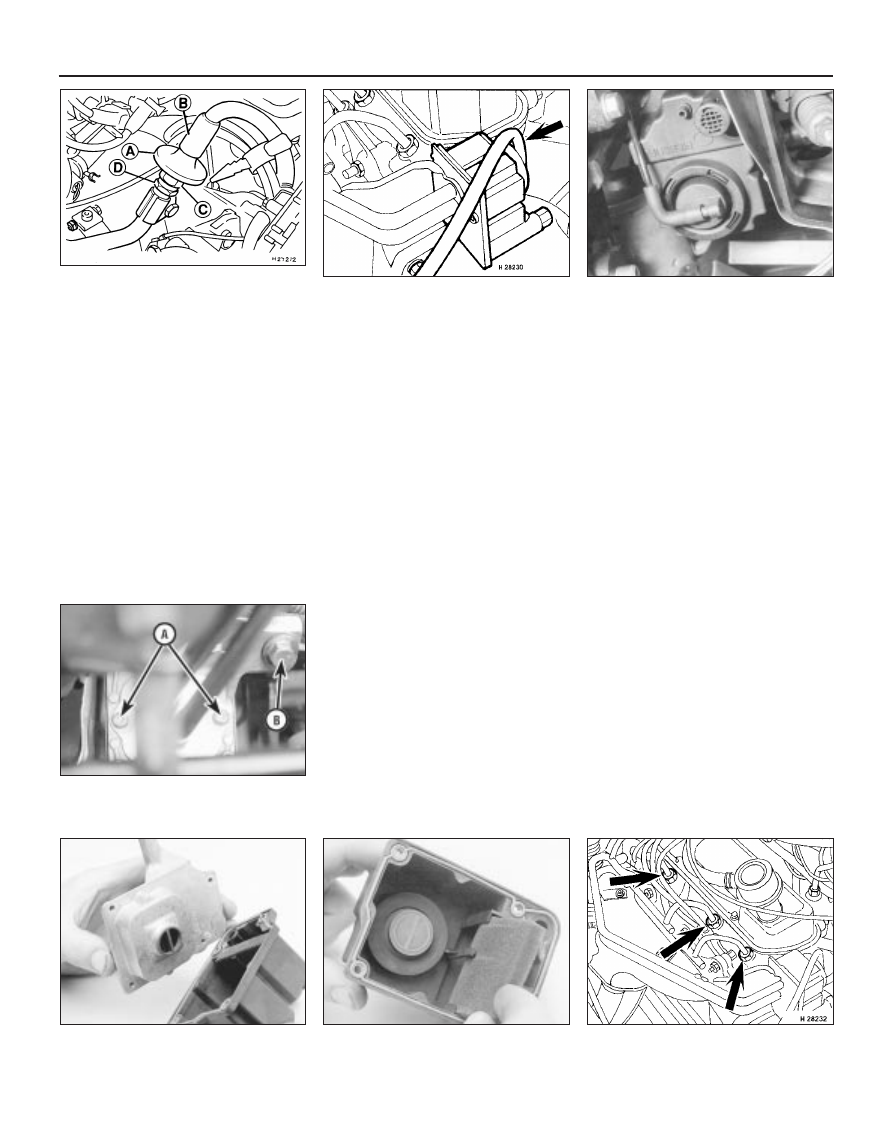
Pulse-air check valve (CVH engines)
16 Disconnect the battery negative (earth)
lead (refer to Chapter 5, Section 1).
17 Detach the air hoses from the check valve
(see illustration).
18 Hold the lower tube nut at the base of the
valve firm with a suitable spanner, and
unscrew the valve using a spanner fitted on
the upper nut.
19 Refit in the reverse order of removal.
Ensure that the valve is correctly positioned
before fully tightening the tube nut against the
valve nut.
Pulse-air valve, filter and housing
(HCS engines)
20 Disconnect the battery negative (earth)
lead (refer to Chapter 5, Section 1).
21 Disconnect the vacuum hose from the
rear of the pulse-air valve assembly (see
illustration).
22 Undo the retaining screws, and withdraw
the air-valve, filter and housing assembly from
the mounting bracket.
23 To dismantle the filter housing, undo the
four screws and separate the top from the
base of the housing; extract the foam filter,
and clean it in a suitable solvent. If any of the
housing’s components are worn or damaged,
the assembly must be renewed.
24 Refitting is the reverse of the removal
procedure.
Pulse-air valve, filter and housing
(Zetec engines)
25 Apply the handbrake, then raise the front
of the vehicle, and support it securely on axle
stands.
26 Disconnect the battery negative (earth)
lead (refer to Chapter 5, Section 1).
27 Disconnect the vacuum hose from the
base of the filter housing (see illustration).
28 Remove the air cleaner air inlet ducting for
access (refer to Chapter 4).
29 Remove the screws securing the filter
housing to the piping, unscrew the mounting
bolt, then withdraw the housing (see
illustration).
30 To dismantle the filter housing, undo the
four screws and separate the top from the
base of the housing. Extract the foam filter,
and clean it in a suitable solvent (see
illustrations). If any of the housing’s
components are worn or damaged, the
assembly must be renewed.
31 Refitting is the reverse of the removal
procedure.
Pulse-air solenoid valve
32 Disconnect the battery negative (earth)
lead (refer to Chapter 5, Section 1).
33 Releasing its wire clip, unplug the
electrical connector, then release the valve
from its mounting bracket. Withdraw the
valve, then label and disconnect the two
vacuum hoses.
34 Refitting is the reverse of the removal
procedure; ensure that the hoses are correctly
reconnected.
Pulse-air piping (HCS and CVH
engines)
35 Disconnect the battery negative (earth)
lead (refer to Chapter 5, Section 1).
36 Remove the air cleaner if necessary for
improved access (refer to Chapter 4).
37 Disconnect the vacuum hose from the
pulse-air valve.
38 Unbolt and detach the air tube from its
fixing to the exhaust manifold, cylinder head
and transmission, according to engine type.
39 Loosen off the four nuts securing the air
delivery tubes to the cylinder head exhaust
ports, then carefully withdraw the delivery
tubes as a unit (see illustration). Do not apply
undue force to the tubes as they are
detached.
40 Carefully clean the piping, particularly its
6•10 Emissions control systems
6.39 Pulse-air piping retaining nuts
(arrowed) on HCS engines
6.30B . . . and withdraw the foam filter for
cleaning, if required
6.30A Remove the four screws to release
the filter housing top from the base . . .
6.29 . . . then undo screws “A” to
disconnect the piping and mounting
bolt “B” to release the housing
6.27 Disconnect the vacuum hose from
the base of the filter housing . . .
6.21 Vacuum hose connection (arrowed)
to pulse-air valve on HCS engines
6.17 Pulse-air check valve and
connections on CVH engines
A Check valve
C Check valve upper nut
B Air hose
D Lower tube nut