Ford Orion. Manual - part 24
14 Where the vehicle is fitted with manual
transmission, disconnect the clutch cable (see
Chapter 8).
15 Marking or labelling all components as
they are disconnected (see paragraph 5
above), disconnect the engine wiring
connectors as follows:
a)
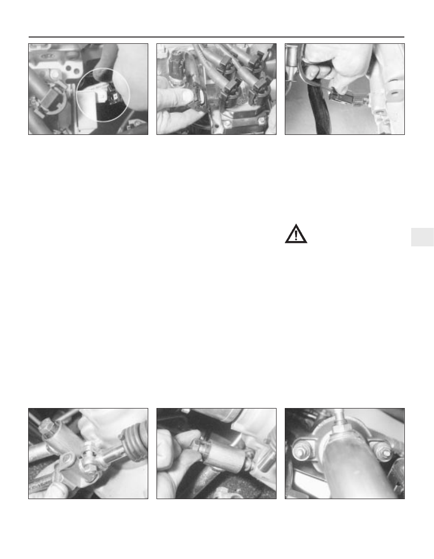
The multi-plug from the DIS ignition coil
(see illustration).
b)
The radio interference suppressor from
the DIS ignition coil (see illustration).
c)
The reversing light switch multi-plug (see
illustration).
d)
The engine main wiring loom multi-plug
behind the DIS ignition coil.
e)
The crankshaft speed/position sensor and
vehicle speed sensor multi-plugs.
f)
The oxygen sensor multi-plug.
16 Unbolt the exhaust manifold heat shield,
and lift it clear.
17 Remove the auxiliary drivebelt (see
Chapter 1).
18 Marking or labelling all components as
they are disconnected (see paragraph 6
above) and catching as much as possible of
the escaping coolant in the drain tray,
disconnect the cooling system hoses and
pipes as follows - refer to Chapter 3 for further
details, if required:
a)
The coolant hoses at the thermostat
housing.
b)
The coolant hose at the metal cross pipe
lower connection.
c)
The radiator top and bottom hoses.
19 Undo the nut securing the power steering
pump pressure pipe clip to the timing belt
cover. Release the unions and clips, and
disconnect the pump pressure and return
lines. Collect the fluid in a suitable container,
and plug the disconnected unions. Lift the
power steering fluid reservoir out of its
bracket, and move it clear of the engine.
20 Apply the handbrake, then raise the
vehicle and support it securely on axle stands,
then remove the front roadwheels.
21 Refer to Chapter 5 if necessary, and
disconnect the wiring from the starter motor
and alternator.
22 Disconnect the oil pressure switch wiring
connector.
23 On automatic transmission models,
disconnect the starter inhibitor switch wiring
and disconnect the selector cable (see
Chapter 7B). Secure the cable clear of the
engine/transmission.
24 Where the vehicle is fitted with manual
transmission, disconnect the gearchange
linkage and transmission support rod from the
rear of the transmission - make alignment
marks as they are disconnected (see
illustrations).
25 On automatic transmission models, clean
around the unions, then disconnect the fluid
pipes from the transmission. Plug the
openings in the transmission and the pipe
unions after removal.
26 Unscrew the nuts to disconnect the
exhaust system front downpipe from the
manifold (see illustration). Undo the nuts
securing the catalytic converter to the rear
part of the exhaust system, and remove the
converter and downpipe assembly.
27 Where the vehicle is fitted with air
conditioning, refer to Chapter 3 and
disconnect any components that are likely to
impede removal of the engine/transmission
from below.
Warning: Do not disconnect the
refrigerant hoses.
28 Disconnect both anti-roll bar links from
their respective suspension struts, and both
track rod end ball joints from their spindle
carriers (see Chapter 10).
29 Noting the direction of fitting, unscrew the
retaining nut and withdraw the Torx-type
clamp bolt securing the lower suspension arm
to the spindle carrier on each side.
30 Insert a suitable lever between the right-
hand driveshaft inner joint and the
transmission housing, and prise free the
driveshaft from the transmission; be prepared
for oil spillage from the transmission case
through the vacated driveshaft aperture. As it
is being prised free, simultaneously pull the
roadwheel outwards on that side to enable the
driveshaft inboard end to separate from the
transmission. Once it is free, suspend and
support the driveshaft from the steering gear,
to prevent unnecessary strain being placed on
the driveshaft joints. The outer joint must not
be angled in excess of 45
∞
, the inner joint no
Engine removal and general engine overhaul procedures 2D•13
6.15C . . . and the reversing light switch
6.15B . . . the radio interference
suppressor . . .
6.15A Disconnect the wiring multi-plug
(arrowed) from the ignition coil ..
6.26 Disconnect the exhaust system front
downpipe from the manifold
6.24B . . . and transmission support rod
6.24A Disconnect the gearchange
linkage . . .
2D