Ford Orion. Manual - part 23
23 Locate a jack under the transmission, and
raise it to take the weight of the transmission.
24 Unscrew and remove the remaining
engine-to-transmission retaining bolts on the
upper flange.
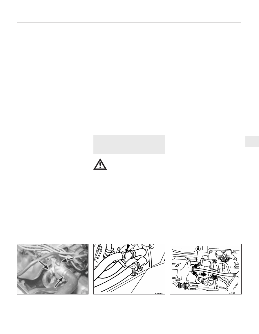
25 Check around the engine to ensure that all of
the relevant fixings and attachments are
disconnected and out of the way for the removal.
26 Enlist the aid of an assistant, then move
the engine forwards and away from the
transmission, whilst simultaneously raising the
transmission. When the engine is separated
from the transmission, carefully guide it up
and out of the engine compartment. Do not
allow the weight of the engine to hang on the
transmission input shaft at any point during
the removal (or refitting) of the engine. When
the engine sump is clear of the vehicle, swing
the power unit out of the way, and lower it
onto a trolley (if available). Unless a mobile
hoist is being used, it will be necessary to
move the vehicle rearwards and out of the
way in order to allow the engine to be lowered
for removal. In this instance, ensure that the
weight of the transmission is well supported
as the vehicle is moved.
27 While the engine is removed, check the
mountings; renew them if they are worn or
damaged. Similarly, check the condition of all
coolant and vacuum hoses and pipes (see
Chapter 1); components that are normally
hidden can now be checked properly, and
should be renewed if there is any doubt at all
about their condition. Also, take the
opportunity to overhaul the clutch components
(see Chapter 8). It is regarded by many as good
working practice to renew the clutch assembly
as a matter of course, whenever major engine
overhaul work is carried out. Check also the
condition of all components (such as the
transmission oil seals) disturbed on removal,
and renew any that are damaged or worn.
Refitting
28 Refitting is in general, a reversal of the
removal procedure, but the following special
points should be noted.
29 Before coupling the engine to the
transmission, apply a thin smear of high-
melting-point grease onto the transmission input
shaft splines. If the clutch has been removed,
ensure that the clutch disc is centralised, and
disconnect the clutch cable from the release
lever on the transmission casing.
30 Tighten all fixings to their recommended
torque wrench settings.
31 Check that the mating faces are clean,
and fit a new exhaust downpipe-to-manifold
gasket and self-locking nuts when
reconnecting this joint.
32 Ensure that all wiring connections are
correctly and securely made.
33 Remove the plugs from the fuel lines before
reconnecting them correctly and securely.
34 Reconnect and adjust the accelerator and
choke cables as described in Chapter 4. The
refitting details for the air cleaner unit are also
given in that Chapter.
35 Renew any coolant hoses (and/or
retaining clips) that are not in good condition.
36 Refer to Chapter 8 for details on
reconnecting the clutch cable.
37 When the engine is fully refitted, check
that the various hoses are connected, and
then top-up the engine oil and coolant levels
as described in Chapter 1.
38 When engine refitting is completed, refer to
Section 22 for the engine start-up procedures.
5
Engine/transmission -
removal and refitting
(CVH engine)
3
Warning: Petrol is extremely
flammable, so take extra
precautions when disconnecting
any part of the fuel system. Don’t
smoke, or allow naked flames or bare light
bulbs, in or near the work area, and don’t
work in a garage where a natural-gas
appliance (such as a clothes dryer or water
heater) is installed. If you spill petrol on
your skin, rinse it off immediately. Have a
fire extinguisher rated for petrol fires
handy, and know how to use it.
Note: Read through the entire Section, as well
as reading the advice in the preceding Section,
before beginning this procedure. The engine
and transmission are removed as a unit,
lowered to the ground and removed from
underneath, then separated outside the vehicle.
Removal
1 On all fuel-injected engines, refer to
Chapter 4B and depressurise the fuel system.
2 Disconnect the battery negative (earth) lead
(refer to Chapter 5, Section 1).
2 Referring to Chapter 1 for details, drain the
coolant and the engine oil. Refit the drain plug
to the sump on completion.
4 Refer to Chapter 11 for details, and remove
the bonnet. Store it in a safe area where it will
not get damaged.
5 Remove the air cleaner unit as described in
Chapter 4. On 1.6 litre EFi fuel-injected
models, remove the air inlet components and
the complete air cleaner unit.
6 Release the retaining clips and detach the
coolant top hose, the heater hose and the
radiator overflow hose from the thermostat
housing. Disconnect the coolant hose from the
inlet manifold, and the bottom hose from the
water pump and/or the radiator (see
illustrations). On 1.4 litre CFi fuel-injected
models, also disconnect the coolant hose from
the injection unit. On 1.6 EFi models, detach
the heater hose Y-connector. Allow for coolant
spillage as the hoses are detached, note their
routing, and position them out of the way.
7 Refer to Chapter 4 for details, and
disconnect the accelerator cable from the
throttle linkage and support/adjuster bracket.
Where applicable, also disconnect the choke
cable. Position the cable(s) out of the way.
8 On carburettor models, disconnect the fuel
supply hose from the fuel pump, and the
return hose from the carburettor.
9 On CFi models, detach the fuel hose at the
injector/pressure regulator unit, and the return
line, by compressing the couplings whilst
pulling the hoses free from their connections.
On EFi models, unscrew the union nut to
detach the fuel line from the fuel rail; release
the retaining clip to detach the return pipe
from the pressure regulator. Plug the exposed
ends of the hoses and connections, to
prevent fuel spillage and the ingress of dirt.
Position the hoses out of the way.
10 Press the clamp ring inwards, and simul-
taneously pull free the brake servo hose from
the inlet manifold. Position it out of the way.
11 On CFi and EFi models, detach the
vacuum hose from the MAP sensor, and the
hose between the carbon canister and the fuel
injection unit (see illustration).
Engine removal and general engine overhaul procedures 2D•9
5.11 Vacuum hose to MAP sensor (A) and
brake servo (B)
5.6B Heater coolant hoses and Y-
connector on 1.6 litre EFi fuel-injected
models
5.6A Coolant hose connections to the
thermostat (arrowed)
2D