Ford Orion. Manual - part 21
2D
HCS engine
Cylinder head
Maximum permissible gasket surface distortion
(measured over full length) . . . . . . . . . . . . . . . . . . . . . . . . . . . . . . . . . . .
0.15 mm
Valve seat angle (inlet and exhaust) . . . . . . . . . . . . . . . . . . . . . . . . . . . .
45º
Valve seat width (inlet and exhaust) . . . . . . . . . . . . . . . . . . . . . . . . . . . .
1.18 to 1.75 mm*
*The inlet and exhaust valves have special inserts which cannot be recut using conventional tools.
Valves - general
Inlet
Exhaust
Valve lift . . . . . . . . . . . . . . . . . . . . . . . . . . . . . . . . . . . . . . . . . . . . . . . . .
8.86 to 9.26 mm
8.96 to 9.36 mm
Valve length . . . . . . . . . . . . . . . . . . . . . . . . . . . . . . . . . . . . . . . . . . . . . .
103.7 to 104.4 mm
104.2 to 104.7 mm
Valve head diameter . . . . . . . . . . . . . . . . . . . . . . . . . . . . . . . . . . . . . . . .
34.40 to 34.60 mm
28.90 to 29.10 mm
Valve stem diameter . . . . . . . . . . . . . . . . . . . . . . . . . . . . . . . . . . . . . . . .
7.0 mm
7.0 mm
Valve stem-to-guide clearance . . . . . . . . . . . . . . . . . . . . . . . . . . . . . . . .
0.020 to 0.069
0.046 to 0.095
Pistons and piston rings
Piston diameter:
Standard 1 . . . . . . . . . . . . . . . . . . . . . . . . . . . . . . . . . . . . . . . . . . . . .
73.91 to 73.92 mm
Standard 2 . . . . . . . . . . . . . . . . . . . . . . . . . . . . . . . . . . . . . . . . . . . . .
73.92 to 73.93 mm
Standard 3 . . . . . . . . . . . . . . . . . . . . . . . . . . . . . . . . . . . . . . . . . . . . .
73.93 to 73.94 mm
Oversize 0.5 mm . . . . . . . . . . . . . . . . . . . . . . . . . . . . . . . . . . . . . . . . .
74.46 to 74.49 mm
Oversize 1.0 mm . . . . . . . . . . . . . . . . . . . . . . . . . . . . . . . . . . . . . . . . .
74.96 to 74.99 mm
Piston-to-cylinder bore clearance . . . . . . . . . . . . . . . . . . . . . . . . . . . . .
0.015 to 0.050 mm
Piston ring end gap - installed:
Compression rings . . . . . . . . . . . . . . . . . . . . . . . . . . . . . . . . . . . . . . .
0.25 to 0.45 mm
Oil control ring . . . . . . . . . . . . . . . . . . . . . . . . . . . . . . . . . . . . . . . . . .
0.20 to 0.40 mm
Ring gap position:
Top compression ring . . . . . . . . . . . . . . . . . . . . . . . . . . . . . . . . . . . . .
Offset 180º from oil control ring gap
Second compression ring . . . . . . . . . . . . . . . . . . . . . . . . . . . . . . . . . .
Offset 90º from oil control ring gap
Oil control ring . . . . . . . . . . . . . . . . . . . . . . . . . . . . . . . . . . . . . . . . . .
Aligned with gudgeon pin
Chapter 2 Part D: Engine removal
and general engine overhaul procedures
Camshaft and tappets - removal, inspection and refitting
(HCS engine) . . . . . . . . . . . . . . . . . . . . . . . . . . . . . . . . . . . . . . . . . 11
Compression test - description and interpretation . . .
See Chapter 1
Crankshaft - inspection . . . . . . . . . . . . . . . . . . . . . . . . . . . . . . . . . . . 16
Crankshaft - refitting and main bearing running clearance check . . 20
Crankshaft - removal . . . . . . . . . . . . . . . . . . . . . . . . . . . . . . . . . . . . . 13
Cylinder block/crankcase - cleaning and inspection . . . . . . . . . . . . 14
Cylinder head - dismantling . . . . . . . . . . . . . . . . . . . . . . . . . . . . . . .
8
Cylinder head - reassembly . . . . . . . . . . . . . . . . . . . . . . . . . . . . . . . 10
Cylinder head and valve components - cleaning and inspection . . .
9
Engine - initial start-up after overhaul . . . . . . . . . . . . . . . . . . . . . . . . 22
Engine - removal and refitting (HCS engine) . . . . . . . . . . . . . . . . . . .
4
Engine overhaul - dismantling sequence . . . . . . . . . . . . . . . . . . . . .
7
Engine overhaul - general information . . . . . . . . . . . . . . . . . . . . . . .
2
Engine overhaul - reassembly sequence . . . . . . . . . . . . . . . . . . . . . 18
Engine removal - methods and precautions . . . . . . . . . . . . . . . . . . .
3
Engine/transmission - removal and refitting (CVH engine) . . . . . . . .
5
Engine/transmission - removal and refitting (Zetec engine) . . . . . . .
6
General information . . . . . . . . . . . . . . . . . . . . . . . . . . . . . . . . . . . . . .
1
Main and big-end bearings - inspection . . . . . . . . . . . . . . . . . . . . . . 17
Piston/connecting rod assemblies - inspection . . . . . . . . . . . . . . . . 15
Piston/connecting rod assemblies - refitting and big-end
bearing clearance check . . . . . . . . . . . . . . . . . . . . . . . . . . . . . . . . 21
Piston/connecting rod assemblies - removal . . . . . . . . . . . . . . . . . . 12
Piston rings - refitting . . . . . . . . . . . . . . . . . . . . . . . . . . . . . . . . . . . . 19
2D•1
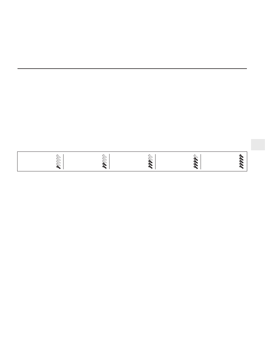
Easy, suitable for
novice with little
experience
Fairly easy, suitable
for beginner with
some experience
Fairly difficult,
suitable for competent
DIY mechanic
Difficult, suitable for
experienced DIY
mechanic
Very difficult,
suitable for expert
DIY or professional
Degrees of difficulty
Specifications
Contents