Ford Orion. Manual - part 19
12 Using a micrometer, measure the
diameter of each journal at several points. If
the diameter of any one journal is less
than the specified value, renew the cam-
shaft.
13 To check the bearing journal running
clearance, remove the hydraulic tappets, use
a suitable solvent and a clean lint-free rag to
clean carefully all bearing surfaces, then refit
the camshafts and bearing caps with a strand
of Plastigage across each journal. Tighten the
bearing cap bolts to the specified torque
wrench setting (do not rotate the camshafts),
then remove the bearing caps and use the
scale provided to measure the width of the
compressed strands. Scrape off the
Plastigage with your fingernail or the edge of a
credit card - don’t scratch or nick the journals
or bearing caps.
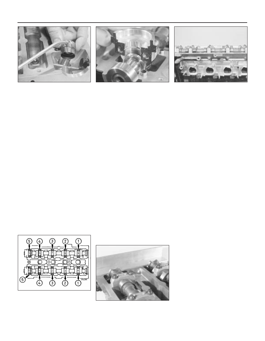
14 If the running clearance of any bearing is
found to be worn to beyond the specified
service limits, fit a new camshaft and repeat
the check; if the clearance is still excessive,
the cylinder head must be renewed.
15 To check camshaft endfloat, remove the
hydraulic tappets, clean the bearing surfaces
carefully, and refit the camshafts and bearing
caps. Tighten the bearing cap bolts to the
specified torque wrench setting, then
measure the endfloat using a DTI (Dial Test
Indicator, or dial gauge) mounted on the
cylinder head so that its tip bears on the
camshaft right-hand end.
16 Tap the camshaft fully towards the gauge,
zero the gauge, then tap the camshaft fully
away from the gauge, and note the gauge
reading. If the endfloat measured is found to
be at or beyond the specified service limit, fit
a new camshaft and repeat the check; if the
clearance is still excessive, the cylinder head
must be renewed.
Refitting
17 On reassembly, liberally oil the cylinder
head hydraulic tappet bores and the tappets
(see illustration). Note that if new tappets are
being fitted, they must be charged with clean
engine oil before installation. Carefully refit the
tappets to the cylinder head, ensuring that
each tappet is refitted to its original bore, and
is the correct way up. Some care will be
required to enter the tappets squarely into
their bores.
18 Liberally oil the camshaft bearings and
lobes. Ensuring that each camshaft is in its
original location, refit the camshafts, locating
each so that the slot in its left-hand end is
approximately parallel to, and just above, the
cylinder head mating surface.
19 Ensure that the locating dowels are
pressed firmly into their recesses, and check
that all mating surfaces are completely clean,
unmarked and free from oil. Apply a thin film
of suitable sealant (Ford recommend
Loctite 518) to the mating surfaces of each
camshaft’s right-hand bearing cap (see
illustration). Referring to paragraph 6 of
Section 12, some owners may wish to fit the
new camshaft oil seals at this stage.
20 All camshaft bearing caps have a single-
digit identifying number etched on them (see
illustration). The exhaust camshaft’s bearing
caps are numbered in sequence 0 (right-hand
cap) to 4 (left-hand cap), the inlet’s 5 (right-
hand cap) to 9 (left-hand cap); see illus-
tration 13.21 for details. Each cap is to be fitted
so that its numbered side faces outwards, to
the front (exhaust) or to the rear (inlet).
21 Ensuring that each cap is kept square to
the cylinder head as it is tightened down, and
working in the sequence shown, tighten the
camshaft bearing cap bolts slowly and by one
turn at a time, until each cap touches the
cylinder head (see illustration). Next, go
round again in the same sequence, tightening
the bolts to the first stage torque wrench
setting specified, then once more, tightening
them to the second stage setting. Work only
as described, to impose gradually and evenly
the pressure of the valve springs on the caps.
Fit the camshaft-aligning tool; it should slip
into place as described in paragraph 8 of
Section 10 (see illustration).
22 Wipe off all surplus sealant, so that none
is left to find its way into any oilways. Follow
the sealant manufacturer’s manuals as to
the time needed for curing; usually, at least an
hour must be allowed between application of
the sealant and starting the engine.
23 If using Ford’s recommended procedure,
fit new oil seals to the camshafts as described
in paragraph 5 of Section 12.
24 Using the marks and notes made on
dismantling to ensure that each is refitted to
its original camshaft, refit the toothed pulleys
to the camshafts, tightening the retaining
bolts loosely. Slip the timing belt back onto
the pulleys (refer to paragraph 19 of Sec-
tion 10) and tighten the bolts securely - use
the forked holding tool described in
paragraph 16 of Section 10.
25 The remainder of the reassembly
procedure, including checking the camshaft
alignment (valve timing) and setting the timing
belt tension, is as described in paragraphs 15
to 25 of Section 10.
2C•14 Zetec engine – in-car engine repair procedures
13.21B Fit camshaft-aligning tool to set
TDC position while camshaft toothed
pulleys are refitted
13.21A Camshaft bearing cap tightening
sequence
Note: View from front of vehicle - locate
bearing caps according to etched numbers,
aligned as described in text
13.20 Etched marks on camshaft bearing
caps must be arranged as shown, and face
outwards
13.19 Apply sealant to mating surface of
camshaft right-hand bearing caps
13.17 Oil liberally when refitting hydraulic
tappets