Ford Orion. Manual - part 13
 

  Index      Ford     Ford Orion - service and repair manual


Search            


Content   ..  11  12  13  14   ..


Ford Orion. Manual - part 13


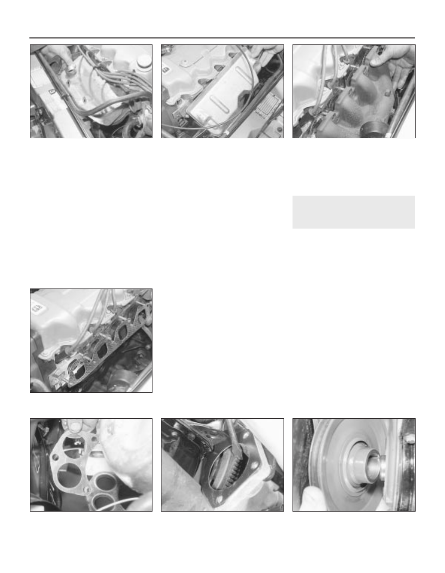
gained by first removing the shroud (see
illustrations)
.
On vehicles equipped with a pulse-air
system, remove the pulse-air piping as
described in Chapter 6.
Support the exhaust downpipe on a jack or
suitable blocks, and undo the down pipe-to-
manifold retaining nuts. Separate the pipe
from the manifold, and remove the gasket. On
catalytic converter-equipped vehicles, take
care not to stretch the oxygen sensor wiring,
where applicable; if necessary, disconnect the
sensor’s multi-plug.
Undo the retaining nuts and withdraw the
manifold from the cylinder head studs (see
illustration)
. Remove the manifold gasket.

Inspection

Use a scraper to remove all traces of old
gasket material and carbon deposits from the
manifold and cylinder head mating surfaces. If
the gasket was leaking, have the manifold
checked for warpage at an automotive
machine shop, and have it resurfaced if
necessary.
Provided both mating surfaces are clean
and flat, a new gasket will be sufficient to
ensure the joint is gastight. Do not use any
kind of exhaust sealant upstream of the
catalytic converter (where applicable).
Note that, on some models, the downpipe
is secured to the manifold by two bolts, with a
coil spring, spring seat and self-locking nut on
each. On refitting, tighten the nuts until they
stop on the bolt shoulders; the pressure of the
springs will then suffice to make a gastight
joint.
Do not overtighten the nuts to cure a leak -
the bolts will shear; renew the gasket and the
springs if a leak is found. The bolts
themselves are secured by spring clips to the
manifold, and can be renewed easily if
damaged.

Refitting

Refit the manifold in the reverse order of
removal, using new gaskets throughout (see
illustrations)
. Tighten the retaining bolts to
their specified torque wrench settings - see
paragraph 8 above. Ensure that all adjacent

wiring and hoses are clear of the exhaust
system and manifold, and on completion
check the system joints for any signs of leaks. 

8

Crankshaft pulley 
removal and refitting

1

Removal

Disconnect the battery negative (earth) lead
(refer to Chapter 5, Section 1).
Apply the handbrake, then raise the vehicle
at the front end, and support it on axle stands.
Unbolt and remove the cover from the
underside of the crankshaft pulley.
Remove the auxiliary drivebelt as described
in Chapter 1.
If timing belt renewal is also intended, set
the engine at TDC as described in Section 4
before removing the crankshaft pulley and
retaining bolt.
To prevent the crankshaft from turning as
the pulley bolt is loosened off, remove the
starter motor as described in Chapter 5, and
then jam the starter ring gear using a suitable
lever (see illustration).
Unscrew and remove the crankshaft pulley
retaining bolt and its washer. Withdraw the
pulley from the front end of the crankshaft
(see illustration). If necessary, lever it free
using a pair of diagonally-opposed levers
positioned behind the pulley.

2B•6 CVH engine – in-car engine repair procedures

8.7  Crankshaft pulley removal

8.6  Using a suitable bar to lock the

flywheel ring gear

7.9B  . . . and manifold-to-exhaust

downpipe connection

7.9A  Fit a new gasket to the exhaust

manifold  . . .

7.4  Removing the exhaust manifold

7.1B  Hot-air shroud removal from the 

1.6 litre EFI fuel injected engine

7.1A  Removing the hot-air shroud from

the 1.6 litre carburettor engine

Refitting

Refit in the reverse order of removal. Tighten
the pulley retaining bolt to the specified torque
setting, and refer to Chapter 1 for details on
refitting the auxiliary drivebelt.
On completion, reconnect the battery earth
lead.

9

Timing belt covers 
removal and refitting

1

Removal

Disconnect the battery negative (earth) lead
(refer to Chapter 5, Section 1).
Undo the two retaining bolts and remove
the upper timing belt cover (see illustration).
Refer to the previous Section for details,
and remove the crankshaft pulley.
Unscrew the two bolts securing the lower
timing belt cover, and remove it (see
illustration)
.

Refitting

Refit in the reverse order of removal.
Tighten the cover retaining bolts to the
specified torque wrench setting.
On completion, reconnect the battery earth
lead.

10 Timing belt - removal, refitting

and adjustment

4

Removal

Referring to the previous Sections for
details, remove the rocker cover, the
crankshaft pulley and the timing belt covers.
Check that the crankshaft is set with the 
No 1 piston at TDC (on its compression
stroke) before proceeding. If necessary, refer
to Section 4 for further details.
To check the timing belt for correct
adjustment, proceed as described in
paragraph 12 below. To remove the belt,
proceed as follows.
Loosen off the two bolts securing the timing

belt tensioner. Using a large screwdriver, prise
the tensioner to one side to release the timing
belt tension. Secure the tensioner in this
position by retightening the bolts (see
illustration)
.
If the original timing belt is to be refitted,
mark it for direction of travel and also the
exact tooth engagement positions on all
sprockets. Slip the belt from the camshaft,
water pump and crankshaft sprockets (see
illustration)
. Whilst the timing belt is
removed, avoid any excessive movement of
the sprockets, otherwise the piston crowns
and valves may come into contact and be
damaged.
If the belt is being removed for reasons
other than routine renewal, check it carefully
for any signs of uneven wear, splitting, cracks
(especially at the roots of the belt teeth) or
contamination with oil or coolant. Renew the
belt if there is the slightest doubt about its
condition. As a safety measure, the belt must
be renewed as a matter of course at the
intervals given in Chapter 1; if its history is
unknown, the belt should be renewed
irrespective of its apparent condition
whenever the engine is overhauled.

Refitting

Before refitting the belt, check that the
crankshaft is still at the TDC position, with the
small projection on the belt sprocket front
flange aligned with the TDC mark on the oil
pump housing (see illustration). Also ensure
that the camshaft sprocket is set with its TDC

pointer aligned with the corresponding timing
mark on the cylinder head. If necessary,
adjust the sprockets slightly. As previously
mentioned, avoid any excessive movement of
the sprockets whilst the belt is removed.
Engage the timing belt teeth with the teeth
of the crankshaft sprocket, and then pull the
belt vertically upright on its right-hand run.
Keep it taut, and engage it with the teeth of
the camshaft sprocket. If the original belt is
being refitted, check that the belt’s direction
of travel is correct, and realign the belt-to-
sprocket marks made during removal, to
ensure that the exact original engagement
positions are retained. When the belt is fully
fitted on the sprockets, check that the
sprocket positions have not altered.
Carefully manoeuvre the belt around the
tensioner, and engage its teeth with the water
pump sprocket, again ensuring that the TDC
positions of the crankshaft and camshaft are
not disturbed as the belt is finally located.
10 Refit the lower timing belt cover, and
tighten its retaining bolts to the specified
torque setting. Refit the crankshaft pulley, and
tighten its retaining bolt to the specified
torque setting.
11 To take up belt slack, loosen off the
tensioner and move it towards the front of the
car to apply an initial tension to the belt.
Secure the tensioner in this position, then
remove the flywheel ring gear locking device.
12 Rotate the crankshaft through two full
revolutions in (the normal direction of travel),
returning to the TDC position (camshaft

CVH engine – in-car engine repair procedures  2B•7

10.4  Timing belt tensioner retaining bolts

(arrowed)

9.4  Lower timing belt cover removal

9.2  Upper timing belt cover removal

10.7  Sprocket and oil pump housing TDC

marks in alignment

10.5  Timing belt removal

2B

sprocket-to-cylinder head). Check that the
crankshaft pulley notch is aligned with the
TDC (0) mark on the lower half of the timing
belt cover.
13 Grasp the belt between the thumb and
forefinger, at the midway point between the
crankshaft and camshaft sprockets on the
right-hand side. If the belt tension is correct, it
should just be possible to twist the belt
through 90º at this point (see illustration). To
adjust the belt, loosen off the tensioner
retaining bolts, move the tensioner as
required using a suitable screwdriver as a
lever, then retighten the retaining bolts. Rotate
the crankshaft to settle the belt, then recheck
the tension. It may take two or three attempts
to get the tension correct. On completion,
tighten the tensioner bolts to the specified
torque wrench setting.
14 It should be noted that this setting is
approximate, and the belt tension should be
rechecked by a Ford dealer with the special
tensioner-setting tool at the earliest
opportunity.
15 Refit the starter motor (refer to Chapter 5).
16 Refit the rocker cover (see Section 5) and
the upper timing belt cover (see Section 9).
17 Refit the auxiliary drivebelt, adjust its
tension as described in Chapter 1, then refit
the crankshaft pulley lower cover.
18 Refit the air cleaner and the air inlet
ducting.
19 On completion, reconnect the battery
earth lead.

11 Timing belt tensioner and

sprockets - removal,
inspection and refitting

4

Tensioner

Set the engine at TDC for No 1 piston as
described in Section 4, then refer to Section 9
and remove the timing belt upper cover.
Loosen off the two bolts securing the timing
belt tensioner. Using a large screwdriver, prise
the tensioner to one side to release the timing
belt tension.
Remove the tensioner bolts, and withdraw
the tensioner from behind the timing belt.

Check the condition of the tensioner,
ensuring that it rotates smoothly on its
bearings, with no signs of roughness or
excessive free play. Renew the tensioner if in
doubt about its condition.
To refit the tensioner, first check that the
engine is still positioned at TDC for No 1
piston, with both the camshaft and crankshaft
sprocket timing marks correctly aligned as
described in Section 4.
Refit the tensioner, guiding it in position
around the timing belt, and secure with the
two bolts. Move the tensioner towards the
front of the car, to apply an initial tension to
the belt. Secure the tensioner in this position.
Adjust the timing belt tension as described
in Section 10, paragraphs 12 to 14.
Refit the timing belt upper cover on
completion.

Camshaft sprocket

Set the engine at TDC for No 1 piston as
described in Section 4, then refer to Section 9
and remove the timing belt upper cover.
10 Loosen off the two bolts securing the
timing belt tensioner. Using a large
screwdriver, prise the tensioner to one side to
release the timing belt tension. Slip the timing
belt off the camshaft sprocket.
11 Pass a bar through one of the holes in the
camshaft sprocket to prevent the camshaft
from rotating, then unscrew and remove the
sprocket retaining bolt. Note that this bolt
must be renewed when refitting the camshaft
sprocket. Remove the sprocket, noting the
Woodruff key fitted to the camshaft; if the key
is loose, remove it for safekeeping.
12 Check the condition of the sprocket,
inspecting carefully for any wear grooves,
pitting or scoring around the teeth.
13 Install the Woodruff key, then fit the
camshaft sprocket with a new retaining bolt.
The threads of the bolt should be smeared
with thread-locking compound prior to fitting.
Tighten the retaining bolt to the specified
torque wrench setting (see illustrations).
14 Check that the engine is still positioned at
TDC for No 1 piston, with both the camshaft
and crankshaft sprocket timing marks
correctly aligned as described in Section 4.

15 Slip the timing belt over the camshaft
sprocket, then move the tensioner towards
the front of the car to apply an initial tension to
the belt. Secure the tensioner in this position.
16 Adjust the timing belt tension as
described in Section 10, paragraphs 12 to 14.
17 Refit the timing belt upper cover on
completion.

Crankshaft sprocket

18 Remove the timing belt as described in
Section 10.
19 The crankshaft sprocket can now be
withdrawn. If it is a tight fit on the crankshaft,
a puller or two large screwdrivers can be used
to release its grip. Withdraw the thrustwasher
and the Woodruff key from the crankshaft.
20 Check the condition of the sprocket,
inspecting carefully for any wear grooves,
pitting or scoring around the teeth.
21 Refit the thrustwasher with its curved side
facing outwards, followed by the Woodruff
key.
22 Lubricate the oil seal and the crankshaft
sprocket with engine oil, then position the
sprocket on the crankshaft with its thrust face
facing outwards.
23 Using the auxiliary drivebelt pulley and its
retaining bolt, draw the sprocket fully into
position on the crankshaft. Remove the
pulley.
24 Refit the timing belt as described in
Section 10.

12 Camshaft oil seal - renewal

4

Remove the camshaft sprocket as
described in the previous Section.
The oil seal is now accessible for removal.
Note its direction of fitting, then using a
suitable screwdriver or a tool with a hooked
end to lever and extract the seal from its
housing (but take care not to damage the
housing with the tool) (see illustration).
Check that the housing is clean before
fitting the new seal. Lubricate the lips of the
seal and the running faces of the camshaft
with clean engine oil. Carefully locate the seal

2B•8 CVH engine – in-car engine repair procedures

11.13B  . . . and tighten the retaining bolt to

the specified torque whilst retaining the

sprocket as shown

11.13A  Refit the camshaft sprocket  . . .

10.13  Checking the tension of the timing

belt

over the camshaft, and drive it squarely into
position using a suitable tube or a socket (see
illustration)
. An alternative method of fitting is
to draw it squarely into position using the old
sprocket bolt and a suitable distance piece.
With the seal fully inserted in its housing,
refit the camshaft sprocket as described in
the previous Section.

13 Camshaft, rocker arms and

tappets - removal, inspection
and refitting

4

Removal

Disconnect the battery negative (earth) lead
(refer to Chapter 5, Section 1).
Refer to the appropriate earlier Sections in

this Chapter, and remove the timing belt
upper cover and the rocker cover.
On carburettor models, refer to Chapter 4
and remove the fuel pump.
Detach, unbolt and remove the ignition coil,
its support bracket and the interference
capacitor from the end of the cylinder head,
as described in Chapter 5.
Undo the retaining nuts and remove the
guides, rocker arms and spacer plates (see
illustrations)
. Keep the respective
components in their original order of fitting by
marking them with a piece of numbered tape,
or by using a suitable sub-divided box.
Withdraw the hydraulic tappets, again
keeping them in their original fitted sequence.
The tappets should be placed in an oil bath
while removed (see illustrations).

Unbolt and remove the lower cover beneath
the crankshaft pulley, then with a spanner
engaged on the crankshaft pulley bolt, turn
the crankshaft over to set the engine on TDC.
Refer to Section 4 for details.
Remove the camshaft sprocket as
described in Section 11.
Extract the camshaft oil seal as described
in Section 12.
10 Before removing the camshaft and its
thrust plate, check and take note of the
amount of camshaft endfloat, using a dial
gauge or feeler gauges. With the camshaft
endfloat measured and noted, unscrew the
two retaining bolts and then extract the
camshaft thrust plate from its pocket at the
front end of the cylinder head (see
illustrations)
.

CVH engine – in-car engine repair procedures  2B•9

13.5A  Undo the rocker arm retaining 

nut  . . .

12.3  Using a socket to tap the camshaft

oil seal into place

12.2  Camshaft front oil seal removal

13.10A  Undo the two retaining bolts

(arrowed)  . . .

13.6B  Store tappets in clearly-marked

container filled with oil to prevent oil loss

13.6A  Removing a hydraulic tappet

13.5D  . . . and spacer plate

13.5C  . . . followed by the rocker arm  . . .

13.5B  . . . withdraw the guide  . . .

2B


Content   ..  11  12  13  14   ..