Content .. 999 1000 1001 1002 ..
Chevrolet Silverado / GMC Sierra. Service manual - part 1001
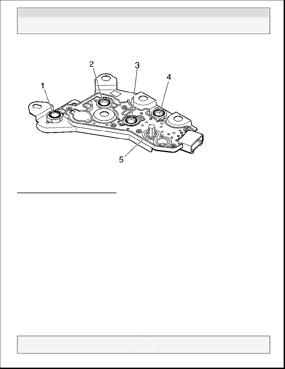
Fig. 521: Pressure Switch Manifold
Courtesy of GENERAL MOTORS CORP.
The PSM is a multiple-switch assembly made up of 3 N/O pressure switches, PS1 (4), PS2 (3),
and PS3 (2) and 1 N/C pressure switch. N/O pressure switches, PS1, PS2, and PS3, correspond
to shift valves SS1, SS2, and SS3. Fluid pressures are fed from shift valves SS1, SS2, and SS3 to
the manual selector valve and to the pressure switches based on the positions of the valves and
shift selector. The shift valve fluid pressures reflect the logic condition at the corresponding
solenoids. This logic indicates the current transmission operating range to the TCM.
The 3 fluid pressure switches corresponding to the shift valves are N/O, contacts not touching,
when no fluid pressure is present, so that electrical current is stopped at the switch. When fluid
pressure is routed to the switch, it moves the diaphragm and upper contact so that the contact
element touches both the positive and ground contacts. This closes the circuit and allows current
to flow from the positive contact and through the switch.
Pressure switch 4 (PS4) (1) corresponding to REVERSE is N/C, since fluid pressure is always
present unless the selector valve is moved to REVERSE. The PSM also contains a transmission
fluid temperature (TFT) sensor thermistor (5) for sump temperature. Changes in sump fluid
temperature are indicated by changes in sensor resistance. Increasing temperature causes
2008 Chevrolet Silverado 1500
2008 TRANSMISSION Automatic Transmission - Allison - Cab & Chassis Sierra, Cab & Chassis Silverado, Sierra &
Silverado