Alfa Romeo Stelvio MCA (2023 year). Manual in english - page 6
 

  Index      Manuals     Alfa Romeo Stelvio MCA (2023 year). Manual in english


Search            copyright infringement  


Content      ..     4      5      6      7     ..


Alfa Romeo Stelvio MCA (2023 year). Manual in english - page 6


 STARTING AND DRIVING

172

that was selected when it was previously

switched off.

200

07226S0001EM

Activation conditions

Once switched on, the system becomes

active only if the following conditions are

met:

the car speed is equal to or higher

than 40 mph (60 km/h) (the system

is deactivated at speeds higher than

110 mph/ 180 km/h);

the lane limit lines are visible at least

on one side;

there are suitable visibility conditions;
the road is straight or with wide radius

bends;

a safe distance is kept from the vehicle

in front;

the direction indicator (for leaving the

lane) is not active.

SYMBOLS AND MESSAGES ON THE

DISPLAY

The Lane Departure Warning system also

advises the driver when the car changes

lane by showing symbols and messages

on the instrument panel display.
The message on the instrument panel

display remains active only until the

main reconfigurable area of the display

is activated (see the description in

the "Display" chapter in the "Knowing

the instrument panel" section)

pressing"MENU VIEW" button located on

the right steering wheel stalk.
Activating the main reconfigurable

area the messages related to the Lane

Departure Warning system will be shown

in this area.
When the system is active and the lane

limits have not been detected, the

display shows the following page, fig. 201.

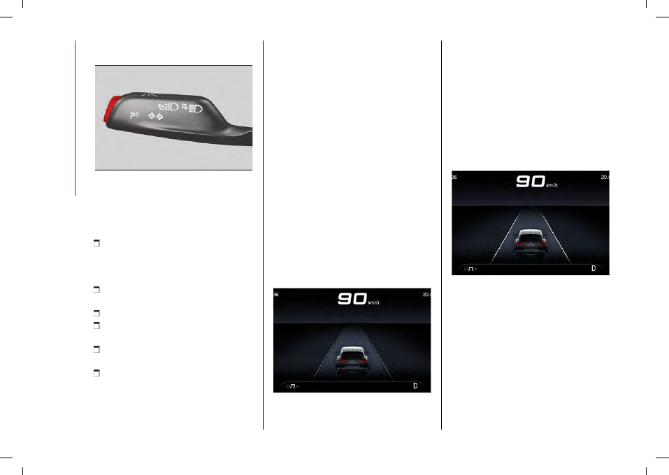
201

9490500

Exiting a lane with detection of a single

limit

When the system is active and only, for

example, the left lane limit has been

detected, the detected lane lights up in

white on the instrument panel display,
fig. 202. The system is ready to provide

visual warnings on the display in the

event of exiting the lane unintentionally

(direction indicator not activated) to the

left.

202

9490497

When the system detects that the car

has approached the lane line and is

about to overtake it, the left line on the

instrument panel display lights up yellow,
fig. 203.

CarManuals2.com

173

203

9490496

The system operates in the same way,

but mirrored, in the event of exiting the

right lane when only the right lane limit

has been detected.

Exiting a lane with detection of both

limits

When the system is active, the lane lines

on the display become white to indicate

the successful detection of the limits.
The system is ready to provide

indications in case of accident lane

departure (direction indicator not

activated).
In accordance with the different

conditions detected, the system can

attract the attention of the driver by

altering the lines that identify the lanes

on the instrument panel display. In

particular, the system can alter their

colour (from white to yellow and vice

versa).

The crossing of a marker line is indicated

on the instrument panel by a flashing

red line and acoustic warning emitted

from the speakers on the side of the lane

limit being crossed (e.g. if the vehicle

is crossing the left line of the lane, the

acoustic warning will come from the

speakers on the left).

Changing the system sensitivity

The system sensitivity intervention can

be adjusted using the "Driver Assistance"

menu and then selecting "Comfort" on

the Connect system.
The possible options are "High" or "Low".

System limited operation warning

59) 60)

If the dedicated message is shown on

the instrument panel display, a condition

limiting the system operation may have

occurred. The possible reasons of this

limitation are something blocking the

camera view or a fault.
If an obstruction is signalled, clean the

area of the windscreen by the interior

rear-view mirror.
Although the car can still be driven in

normal conditions, the system may be

not completely available.
When the conditions limiting the system

functions end, this will go back to normal

and complete operation. Should the

fault persist, contact an Alfa Romeo

Dealership.

System Fault Message

If the system switches off and the
system

appears on the instrument

panel display, it means that there is a

failure on the system.
In this case, it is still possible to drive the

vehicle, but you are advised to contact

an Alfa Romeo Dealership as soon as

possible.

IMPORTANT

55)

Projecting loads on the roof of the car

may interfere with the correct operation of

the camera. Before starting make sure the

load is correctly positioned, in order not to

cover the camera operating range.

56)

If the windscreen must be replaced due

to scratches, chipping or breakage, contact

exclusively an Alfa Romeo Dealership. Do

not replace the windscreen on your own, risk

of malfunction! It is advisable to replace the

windscreen if it is damaged in the area of

the camera.

57)

Do not tamper with nor operate on the

camera. Do not close the openings in the

aesthetic cover located under the interior

rear-view mirror. In the event of a failure

of the camera, contact an Alfa Romeo

Dealership.

58)

Do not cover the operating range of the

camera with stickers or other objects. Also

pay attention to other objects on the bonnet

CarManuals2.com

 STARTING AND DRIVING

174

(e.g. a layer of snow) and make sure they do

not interfere with the camera.

59)

The camera may have limited or absent

operation due to weather conditions such

as: heavy rain, hail, thick fog, heavy snow,

formation of ice layers on the windscreen

glass.

60)

Camera operation may also be

compromised by the presence of dust,

condensation, dirt or ice on the windscreen

glass, by traffic conditions (e.g. cars that

are driving not aligned with yours, car

driving in a transverse or opposite way on

the same lane, bend with a small radius of

curvature), by road surface conditions and

by driving conditions (e.g. off-road driving).

Make sure the windscreen is always clean.

Use specific detergents and clean cloths

to avoid scratching the windscreen. The

camera operation may also be limited or

absent in some driving, traffic and road

surface conditions.

LANE KEEPING ASSIST (LKA)

SYSTEM

(where provided)

DESCRIPTION

55) 56) 57) 58)

The Lane Keeping Assist system

makes use of a camera located on the

windscreen to detect the lane limits and

calculate the position of the car within

such limits, in order to make sure that it

remains inside the lane.
When one or both lane limits are

detected and the vehicle approaches one

of them without the driver signalling the

intention to to do so (direction indicator

not on), the system will apply a torque to

the steering wheel to keep the vehicle in

the lane and will generate a visual signal

(the left or right lane will turn yellow).

According to the type of signal set, it can

also emit an acoustic signal and/or apply

a vibration to the steering wheel.
If the vehicle continues to pass the lane

without any intervention by the driver,

the surpassed line will light up on the

instrument panel display (the left or right

lane will turn yellow) to urge the driver to

return the vehicle into the limits of the

lane.

SYSTEM ON/OFF

The system can be turned on/off by
pressing the fig. 204 button or using

the "Driver Assistance" menu and then

selecting "Safety " on the Connect

system.
Each time the engine is started the

system maintains the operating mode

that was selected when it was previously

switched off.
The system is automatically switched off

when a trailer is coupled.

204

07226S0001EM

Activation conditions

Once switched on, the system becomes

active only if the following conditions are

met:

the car speed is equal to or higher

than 40 mph (60 km/h) (the system

is deactivated at speeds higher than

110 mph/ 180 km/h);

the lane limit lines are visible at least

on one side;

CarManuals2.com

175

there are suitable visibility conditions;
the road is straight or with wide radius

bends;

a safe distance is kept from the vehicle

in front;

the direction indicator (for leaving the

lane) is not active.

SYMBOLS AND MESSAGES ON THE

DISPLAY

The Lane Keeping Assist system also

advises the driver when the car changes

lane by showing symbols and messages

on the instrument panel display.
Lane Keeping Assist information can

be displayed in the right-hand dial,
fig. 205, or in the central area (“Driver

Assistance”) of the display.
NOTE The information is only displayed

in the right-hand dial if the “Driver

Assistance” screen is not selected.
The different colours of the icons shown

on the display show the status of the

system (for more information, see the

description under “Lane keeping assist

symbols” in the “Warning lights and

messages” chapter in the “Knowing the

instrument panel” section).

205

9550224

When the system is active and the

lane limits have not been detected,

the display shows the following page,
fig. 206.

206

9490500

Exiting a lane with detection of a single

limit

When the system is active and only, for

example, the right lane limit has been

detected, the detected lane lights up

in white on the display; the system is

ready to provide visual warnings on the

display in the event of unintentional

exiting of the lane (direction indicator

not activated) to the left.
When the system detects that the car

has approached the lane line and is about

to pass it, the right line on the display
lights up in yellow, fig. 207.

207

9490496

If the system intervention lasts longer

than 10 seconds, an additional acoustic

and visual warning will be provided by

displaying a dedicated message on the

instrument panel display to prompt the

driver to regain control of the vehicle.
If Lane Keeping Assist intervenes several

times in a relatively short time without

the driver acting on the steering wheel,

increasingly longer warning tones will be

emitted to draw the driver's attention.
The system operates in the same way,

but mirrored, in the event of exiting the

left lane when only the left lane limit has

been detected.

CarManuals2.com

 STARTING AND DRIVING

176

Exiting a lane with detection of both

limits

When the system is active, the lane lines

on the display become white to indicate

the successful detection of the limits

fig. 208.
The system is ready to provide

indications in case it is accidentally

abandoned (direction indicator not

engaged).

208

9490497

In accordance with the different

conditions detected, the system can

attract the attention of the driver by

altering the lines that identify the lanes

on the instrument panel display. In

particular, the system can alter their

colour (from white to yellow and vice

versa).
The passing of the line is indicated also

by means of an acoustic warning, is

emitted from the loudspeakers on the

side of the lane limit being crossed (e.g. if

the vehicle is crossing the left line of the

lane, the acoustic warning will come from

the loudspeakers on the left).
If the system intervention lasts longer

than 10 seconds, an additional acoustic

and visual warning will be provided by

displaying a dedicated message on the

instrument panel display to prompt the

driver to regain control of the vehicle.
If Lane Keeping Assist intervenes several

times in a relatively short time without

the driver acting on the steering wheel,

increasingly longer warning tones will be

emitted to draw the driver's attention.

Hands presence on the steering wheel

detection

The system is able to detect the

presence of the driver's hands on the

steering wheel:

if you do not put your hands on

the steering wheel and the system

intervenes during a loss of control in a

lateral direction, the instrument panel

display will show dedicated screens and

beeps of progressive duration will be

emitted to prompt you to put your hands

back on the steering wheel;

if you continues not to put your hands

to the steering wheel after the system

intervenes, the read steering wheel and

a dedicated message will appear on the

instrument panel display.
In these two cases, the driver's hands

must be put back on the steering wheel.

Changing the system sensitivity

The system intervention sensitivity can

be adjusted using the "Driver Assistance"

menu on the Connect system. The

possible options are "High" or "Low".

Change of indications provided by the

system

The indications provided by the Lane

Keeping Assist system may be modified

using the Connect system.
Proceed as follows:

use the "Driver Assistance" menu;
select "Settings" and then select

"Warning type" or "Mode" and select one

of the required settings.

System limited operation warning

65) 66)

If the dedicated message is shown on

the instrument panel display, a condition

limiting the system operation may have

occurred. The possible reasons of this

limitation are something blocking the

camera view or a fault.
If an obstruction is signalled, clean the

area of the windscreen by the interior

rear-view mirror.
Although the car can still be driven in

normal conditions, the system may be

not completely available.
When the conditions limiting the system

functions end, this will go back to normal

and complete operation. Should the

CarManuals2.com

177

fault persist, contact an Alfa Romeo

Dealership.

System Fault Message

If the system switches off and the
system

appears on the instrument

panel display, it means that there is a

failure on the system.
In this case, it is still possible to drive the

vehicle, but you are advised to contact

an Alfa Romeo Dealership as soon as

possible.

IMPORTANT

61)

Projecting loads on the roof of the car

may interfere with the correct operation of

the camera. Before starting make sure the

load is correctly positioned, in order not to

cover the camera operating range.

62)

If the windscreen must be replaced due

to scratches, chipping or breakage, contact

exclusively an Alfa Romeo Dealership. Do

not replace the windscreen on your own, risk

of malfunction! It is advisable to replace the

windscreen if it is damaged in the area of

the camera.

63)

Do not tamper with nor operate on the

camera. Do not close the openings in the

aesthetic cover located under the interior

rear-view mirror. In the event of a failure

of the camera, contact an Alfa Romeo

Dealership.

64)

Do not cover the operating range of the

camera with stickers or other objects. Also

pay attention to other objects on the bonnet

(e.g. a layer of snow) and make sure they do

not interfere with the camera.

65)

The camera may have limited or absent

operation due to weather conditions such

as: heavy rain, hail, thick fog, heavy snow,

formation of ice layers on the windscreen

glass.

66)

Camera operation may also be

compromised by the presence of dust,

condensation, dirt or ice on the windscreen

glass, by traffic conditions (e.g. cars that

are driving not aligned with yours, car

driving in a transverse or opposite way on

the same lane, bend with a small radius of

curvature), by road surface conditions and

by driving conditions (e.g. off-road driving).

Make sure the windscreen is always clean.

Use specific detergents and clean cloths

to avoid scratching the windscreen. The

camera operation may also be limited or

absent in some driving, traffic and road

surface conditions.

REAR BACK-UP CAMERA /

DYNAMIC GRIDLINES

DESCRIPTION

The Rear Back-up Camera is located on

the tailgate, near the opening button,
fig. 209.

161)

67)

209

07186V0001EM

Camera activation/deactivation

The function can be

activated/deactivated using the "Driver

Assistance" menu and then selecting

"Comfort" on the Connect system.

Activating the device

After activating the camera, it will be

possible to select one of the following

options:

"

Activate

"

"

Cam Delay

"

CarManuals2.com

 STARTING AND DRIVING

178

"

Camera Guidelines

"

Select "Activate" to activate the camera

view on the Connect system display.
Whenever reverse gear is engaged, the
Connect system display, fig. 210, will

show the area around the car, as seen by

the Rear View Camera.

Controllare l'intera area circostante

210

07186V0060EM

SYMBOLS AND MESSAGES ON THE

DISPLAY

Activating the "Camera Guidelines"

shows the guidelines on the display.

If activated, the grid is positioned on

the image to highlight the width of the

car and the expected reversing path in

accordance with the steering wheel

position.
A superimposed central broken line

indicates the centre of the car to

facilitate parking manoeuvres or tow

hook alignment. The various coloured

areas indicate the distance from the rear

of the car.

The table below shows the approximate
distances for each area fig. 210:

Area

Distance from the

rear of the

vehicle

Red

0 - 1 ft (0 – 30 cm)

Yellow

1 - 3.3 ft (30 cm - 1

m)

Green

3.3 ft (1 m) or more

WARNING When parking, take the

utmost care over obstacles that may be

above or under the operating range of

the camera.

WARNING

161)

Parking and other potentially

dangerous manoeuvres are, however,

always the driver’s responsibility. While

carrying out these manoeuvres, always

make sure that no people (especially

children) or animals are in the area

concerned. The camera is an aid for the

driver, but the driver must never allow

his/her attention to lapse during potentially

dangerous manoeuvres, even those

executed at low speeds. Always keep a slow

speed, so as to promptly brake in the case of

obstacles.

IMPORTANT

67)

It is vital, for correct operation, that

the camera is always kept clean and free

from any mud, dirt, snow or ice. Be careful

not to scratch or damage the camera while

cleaning it. Avoid using dry, rough or hard

cloths. The camera must be washed using

clean water, with the addition of vehicle

shampoo if necessary. In washing stations

which use steam or high-pressure jets, clean

the camera quickly, keeping the nozzle more

than 10 cm away from the sensors. Also, do

not apply stickers to the camera.

REFUELLING THE CAR

162) 163) 164)

Always stop the engine before refuelling.

PETROL ENGINES

Only use unleaded petrol with an octane

number (R.O.N.) not lower than 95

(EN228 specification).

DIESEL ENGINES

Only use Diesel fuel for motor cars

(EN590 specification).

REFUELING PROCEDURE

The fuel flap is unlocked when the central

door locking system is released, while it

is automatically locked when the central

locking system is applied.

CarManuals2.com

179

open flap (1) fig. 211, pressing on the

point shown by the arrow fig. 212;

remove the closing cap (2);
return the cap to its seat (4);
introduce the nozzle in the filler and

refuel;

once refuelling is complete, before

removing the fuel nozzle, wait at least 10

seconds to allow the fuel to flow into the

tank;

then remove the dispenser from the

filler, close the cap and then close the

flap.
The refuelling procedure described

above is illustrated on the label (where

provided) located inside the fuel flap.

211

07226V0042EM

212

07206V0001EM

TOPPING UP AdBlue® DIESEL

EMISSIONS ADDITIVE

(2.2 JTD versions only)

165)

Preliminary Conditions

AdBlue® freezes at temperatures lower

than 12.2 °F (-11 °C). If the car stands for

a long time at this temperature refilling

could be difficult. For this reason, it is

advised to park the car in a garage and/or

heated environment and wait for the

AdBlue® to return to liquid state before

topping up.
Proceed as follows:

park the car on level ground;
switch off the engine by turning the

ignition device to STOP;

open the fuel flap A (1) fig. 214 and then

unscrew and remove the cap (3) (blue)
from the AdBlue® filler and put it in the

stowing position provided (4).

Refilling with nozzles

You can fill up at any AdBlue®

distributor.
Proceed as follows:

insert the AdBlue® nozzle in the filler,

start refilling and stop refilling at the

first shut-off (the shut-off indicates that
the AdBlue® tank is full). Do not proceed

with the refilling, to prevent spillage of
AdBlue®;

extract the nozzle.

Refilling with containers

Proceed as follows:

check the expiration date;
read the advice for use on the label

before pouring the content of the bottle
into the AdBlue® tank;

if systems which cannot be screwed in

(e.g. tanks) are used for refilling, after the

indication appears on the instrument

panel display (see “Indicator lights and

messages" chapter in the “Knowing

the instrument panel” section), fill the
AdBlue® tank with at least 1.1 UK gal (5

litres);

if containers which can be screwed to

the filler are used, the reservoir is full

when the AdBlue® level in the container

stops pouring out. Do not proceed

further.

Opening the flap

To refuel proceed as follows:

CarManuals2.com

 STARTING AND DRIVING

180

AdBlue® level display

The level of AdBlue® inside the tank can

be viewed on the Connect system display
fig. 213.
Proceed as follows:

activate the "Vehicle Information"

function pressing the appropriate widget

on the Connect system display.

press the graphic button 1 fig. 213: the

level 2 of AdBlue® will appear on the

display.
If the AdBlue® level is not in reserve, the

message "OK" will appear on the display.
If the AdBlue® level is insufficient the

message "KO" will appear on the display.

213

12126V2311EM

Operations after refilling

Proceed as follows:

fit the cap (3) fig. 211 back on ‘the

AdBlue® filler by turning it clockwise and

screwing it completely;

set the ignition device to ON (it is not

necessary to start the engine);

wait for the indication on the

instrument panel to switch off before

moving the car. The indication may stay

on for a few seconds to approximately

half a minute. If the engine is started

and the car is moved, the indication

will remain on for longer. This will not

compromise engine operation;

if the AdBlue® was topped up when

the tank was empty, see the “Refilling”

chapter in the “Technical Specifications”

section and wait for 2 minutes before

starting the engine.
WARNING If AdBlue® is spilled out of

the filler neck, clean up well the area and

proceed to filling up again. If the liquid

crystallises, eliminate it with a sponge

and warm water.

WARNING

DO NOT EXCEED THE MAXIMUM

LEVEL: this could cause damage to
the reservoir. AdBlue® freezes under

12.2 °F (-11 °C). Although the system is

designed to operate below the freezing

point of the AdBlue®, it is advisable not

to fill the tank beyond the maximum
level because if the AdBlue® freezes

the system can be damaged. Comply

with the instructions provided in this

paragraph.

If the AdBlue® is spilled on painted

surfaces or aluminium, immediately

clean the area with water and use

absorbent material to collect the fluid

that has been spilled on the ground.

Do not try to start the engine if the

AdBlue® was accidentally added to

the Diesel fuel tank, this can result in

serious engine damage, contact a Alfa

Romeo Dealership.

Do not add additives or other fluids

to AdBlue®, doing so could damage the

system.

The use of non-conforming

or degraded AdBlue® may lead

to indications appearing on the

instrument panel display (see

“Indicator lights and messages" chapter

in the “Knowing the instrument panel”

section).

Never pour AdBlue® into another

container: it could be contaminated.

In case of damage to the sewage

system of exhaust gas resulting from

the use of additives / tap water, the

introduction of diesel fuel, or at least

by not fulfilling the requirements, the

warranty expires.

If the AdBlue® runs out, see the

"Indicator lights and messages" chapter

in the "Knowing the instrument panel”

section to continue using the car

normally.

CarManuals2.com

181

The AdBlue® level is not updated if

the car is parked on a sloping road.

The consumption of AdBlue®

emissions additive depends on the

conditions of use of the car and is

indicated by means of the symbol and a

dedicated message on the instrument

panel display.

Fuels - identification of vehicle

compatibility. Graphic symbol for

consumer information in accordance

with EN16942

The symbols, shown below, make it

easier to recognise the correct fuel type

to use with your car.
Before refuelling, check the symbols

(where provided) inside the fuel

filler flap and compare them with the

symbols shown on the fuel pump (where

provided).

PETROL ENGINES

Inside the flap there is also the fuel type

(UNLEADED FUEL = petrol) and the

symbol (where provided) that certifies

compliance with the EN228 (petrol)
standard fig. 214.

214

07206V0002EM

Symbols for petrol powered cars

E5

: unleaded petrol containing up to 2.7%

(m/m) oxygen and with maximum 5.0%

(V/V) ethanol compliant with the EN228

specification.

E10

: unleaded petrol containing up to

3.7% (m/m) oxygen and with maximum

10.0% (V/V) ethanol compliant with the

EN228 specification.

DIESEL ENGINES

The fuel cap shows the type of fuel
(DIESEL - diesel fuel) fig. 215, while inside

the fuel flap there is the symbol (where

provided) that certifies compliance with

the EN590 standard.

215

07206V0004EM

Symbols for diesel fuelled cars

B7

: diesel containing up to 7% (V/V)

of FAME (Fatty Acid Methyl Esters)

compliant with the EN590 specification.

Emergency diesel version refuelling

Proceed as follows:

open the boot and take out the

dedicated adapter, located under the
load platform fig. 216;

open flap fig. 212, pressing on the point

shown by the arrow;

remove the closing cap;
return the cap to its seat;
insert the adapter into the filler;
when you have finished refuelling,

remove the adapter, close the cap and

then close the flap;

CarManuals2.com

 STARTING AND DRIVING

182

finally put the adaptor back in the

boot.

216

07206V0005EM

Emergency fuel flap opening

In the event of an emergency the fuel flap

can be opened by operating from inside

the boot.

Versions with Cargo Box

Proceed as follows:

open the tailgate and then lift up the

load bed fig. 217;

lift the cover (1) fig. 218 to access the

emergency opening cable (2) fig. 219,

located by the side of the filler;

pull the cable in the direction indicated

by the arrow to release the fuel flap lock;

open the fuel flap by pressing it.

217

04206V0004EM

218

07226V0041EM

219

07226V0043EM

Versions with Cargo Box and space-

saver wheel

(where provided)
Proceed as follows:

open the tailgate and then lift up the

load bed fig. 217;

undo the locking device (1) fig. 220 and

extract the space-saver wheel to reach
the emergency opening cable (1) fig. 221

positioned on the side of the filler;

pull the cord to unlock the fuel flap;

CarManuals2.com

183

open the fuel flap by pressing it.

220

08066V0010EM

221

07226V0044EM

WARNING If the filler compartment is

washed with a high-pressure jet, keep it

at a distance of at least 20 cm.

WARNING

162)

Do not apply any object/cap to the end

of the filler which is not provided for the

car. The use of non-compliant objects/plugs

could cause a pressure increase inside the

tank, resulting in dangerous situations.

163)

Do not approach naked flames or lit

cigarettes to the fuel tank filler: fire risk.

Keep your face away from the fuel filler to

prevent breathing in harmful vapours.

164)

Do not use a mobile phone near the

refuelling pump: risk of fire.

165)

If the AdBlue overheats for a prolonged

period inside the tank to over 50 °C (for

example, due to direct solar irradiation),

the AdBlue may decompose and produce

ammonia vapours. Ammonia vapours have

a pungent odour when the cap of the AdBlue

tank is unscrewed, therefore be careful

not to inhale any ammonia vapours in the

tank outlet. In this concentration, however,

the ammonia vapours are not harmful or

dangerous to health.

AdBlue® (UREA) ADDITIVE FOR

DIESEL EMISSIONS

(2.2 JTD versions only)
The car is equipped with an AdBlue®

(UREA) injection system and Selective

Catalytic Reduction to meet emission

standards.
These two systems ensure compliance

with the diesel emissions requirements;

at the same, they ensure fuel-efficiency,

handling, torque and power. For

messages and system warnings, refer

to the "Warning lights and messages"

chapter in the "Knowing the instrument

panel" section.

AdBlue® (UREA) is considered a very

stable product with a long shelf life.

Stored at temperatures LOWER than

89.6°F (32°C), it has a shelf life of at least

one year.
For more information on the AdBlue®

(UREA) liquid type, see the "Fluids and

Lubricants" chapter in the "Technical

Specifications" section.
The car is provided with an automatic
AdBlue® (UREA) system which, when the

engine is running, allows the system to

work correct at temperatures lower than

12.2°F (–11°C).
WARNING AdBlue® (UREA) freezes at

temperatures lower than 12.2°F (–11°C).

DRIVING TIPS

SAVING FUEL

Below are some suggestions which may

help you save fuel and thus lower the

amount of harmful emissions released

into the atmosphere.

Car maintenance

Checks and maintenance should

be carried out in accordance with

the "Service schedule" (see the

"Maintenance and care" section).

Tyres

Check the tyre pressures at least once

every four weeks: if the pressure is too

low, consumption levels increase as

resistance to rolling is higher.

CarManuals2.com

 STARTING AND DRIVING

184

Unnecessary loads

Do not travel with an overloaded

boot. The weight of the car and its

arrangement greatly affect fuel

consumption and stability.

Electric devices

Use electrical devices only for the

amount of time needed. The heated

rear window, additional headlights,

screen wipers and heater fan require

a considerable amount of energy;

increasing the current uptake increases

fuel consumption (by up to +25% in an

urban cycle).

Climate control system

Using the climate control system will

increase consumption: use standard

ventilation when the temperature

outside permits.

Devices for aerodynamic control

The use of non-certified devices for

aerodynamic control may adversely

affect air drag and consumption levels.

DRIVING STYLE

Start

Do not warm up the engine at low or

high revs when the car is stationary;

this causes the engine to warm up

more slowly, thereby increasing fuel

consumption and emissions. It is

therefore advisable to move off

immediately, slowly, avoiding high

speeds: in this way the engine will warm

up more quickly.

Unnecessary actions

Avoid pressing the accelerator when

stationary.

Gear selection

Use a high gear when traffic and road

conditions allow it. Using a low gear

for faster acceleration will increase

fuel consumption. In the same way,

improper use of a high gear increases

consumption, emissions and engine wear.

Top speed

Fuel consumption considerably increases

as speed increases. Maintain a constant

speed, avoiding unnecessary braking and

acceleration, which cost in terms of both

fuel consumption and emissions.

Acceleration

Accelerating violently severely affects

consumption and emissions: acceleration

should be gradual and should not exceed

the maximum torque.

CONDITIONS OF USE

Cold starting

Short journeys and frequent cold starts

do not allow the engine to reach optimum

operating temperature. Consequently,

both consumption (from +15 to +30%

on the urban cycle) and emissions will

increase.

Traffic and road conditions

High fuel consumption is caused

by heavy traffic, for instance when

travelling in a queue with frequent use of

low gears or in cities with many traffic

lights. Winding mountain roads and rough

road surfaces also adversely affect

consumption.

TRANSPORTING PASSENGERS

Warnings

WARNING It is extremely dangerous to

leave children in a parked car when the

temperature outside is very high. The

heat inside the passenger compartment

may have serious, or even fatal,

consequences.
WARNING Never travel in the internal

load compartment. In the event of an

accident, anyone inside the boot would

be at greater risk of serious or even fatal

injury.
WARNING Ensure that all the occupants

of the car wear their seat belts correctly

and that any children are positioned

correctly on the dedicated child restraint

systems.

TRANSPORTING ANIMALS

Deployment of the airbags may be

dangerous for an animal on the front

seat. It is therefore advisable to arrange

animals on the rear seat inside dedicated

cages restrained by the car’s seat belts.

CarManuals2.com

185

Bear in mind also that, in the event of

a sudden braking or an accident, an

inadequately restrained animal may

be projected within the passenger

compartment, risking injury to the animal

itself and the other occupants of the car.

EXHAUST GAS

Adequate maintenance of the exhaust

system represents the best protection

against leaks of carbon monoxide into

the passenger compartment.
Should an unusual noise from the

exhaust system or the presence

of exhaust gas in the passenger

compartment be identified, or if the

underbody or rear part of the car is

damaged, have the entire exhaust

system and adjoining bodywork areas

checked to identify any components

which are broken, damaged, worn or have

moved from their correct fitting position.

For these operations, contact an Alfa

Romeo Dealership.

QV VERSION

PERFORMANCE

For safe driving, it is essential,

particularly during the first days of

use, to get to know the car by driving

carefully and gradually discovering its

performance.

BRAKES

166)

WARNING Water, ice and salt spread on

the roads may deposit on the brake discs,

reducing braking efficiency the first time

the brakes are applied.
WARNING To obtain the maximum

efficiency of the braking system, a

bedding-in period of about 500 km is

needed: during this period it is better

to avoid sharp, repeated and prolonged

braking.
The car braking system may optionally

fit four carbon-ceramic material brake

discs, one on each wheel.
In order to guarantee the maximum

braking capacity for the first use, Alfa

Romeo performs a "run-in" procedure for

discs and pads directly at the factory.
The use of carbon-ceramic material

brake discs guarantees braking features

(better deceleration/pedal load ratio,

braking distances, fading resistance)

proportional to the dynamic features

of the car in addition to considerably

decreasing the unsprung component

weight.
The materials used and the structural

features of the system could generate

anomalous noises which have absolutely

no adverse effect on correct operation

and reliability of the braking system.

Greater pressure may need to be applied

to the brake pedal the first time to keep

the same braking capacity in presence

of condensation or salt on the braking

surfaces, for example after washing or if

the car is not used for a long time.
WARNING Given the high technological

level of this system, any servicing on

it must be performed by a Alfa Romeo

Dealership which exclusively has the

skills needed for the repair operations.
WARNING In case of intensive,

high-performance use of the car, have

the efficiency of the carbon-ceramic

material braking system inspected as

shown on the Service Schedule at an Alfa

Romeo Dealership.

Overheating of the brakes

The braking system components may

overheat when driving on mountain roads

with steep gradients or during sporty use

of the car. When this happens, there may

be noise/vibrations while braking.
When you reach the destination, do not

stop the engine immediately, but leave it

idling for a few minutes to let the braking

system components cool down and to

lubricate the engine parts properly.
To make the car safe when it is parked,

apply the safety provisions of the

Highway Code before leaving the car:

engage P (Park) mode;

CarManuals2.com

 STARTING AND DRIVING

186

position the wheels at full lock;
engage the electric parking brake;
when parked on a steep slope, place

chocks or stones behind the wheels.

DRIVING ON RACE TRACKS

Before driving on a track using a racing

style, it is necessary to:

Attend a race track driving course.
Check the liquid levels in the engine

compartment. For more information,

see the “Checking levels” chapter in the

“Maintenance and care” section;

Have the vehicle inspected at a

Dedicated Alfa Romeo Dealership.
Remember that the car was not designed

to be driven exclusive on the race track

and that this use increases stress and

component wear.

Preheating the carbon ceramic material

brake discs

The brake discs must be warmed up

to make them fully efficient. You are

advised to perform the following

procedure:

brake nine times from 80 mph

(130 km/h) to 20 mph (30 km/h) with

deceleration equal to 0.7 g (the

longitudinal acceleration value is shown

on the instrument panel display by

setting “Race” mode and selecting the

“Performance” page) with 20 second

intervals between brake applications;

keep the car at a speed comprised

between 37 mph (60 km/h) and 60 mph

(100 km/h) and do not brake for 240

seconds to allow the brakes to cool

down;

then brake three times from 230

mph (200 km/h) to 20 mph (30 km/h)

with deceleration equal to 1.1 g (ABS

operation) with 30 second intervals

between brake applications; keep the car

at a speed comprised between 37 mph

(60 km/h) and 60 mph (100 km/h) and do

not brake for 300 seconds to allow the

brakes to cool down.

WARNING

166)

After the car has been stopped for a

long time in a very cold place (temperature

below 0 °C), for the first five brakes, the

carbon-ceramic braking system efficiency is

not optimal, so you may need slightly more

pressure on the brake pedal.

TOWING TRAILERS

(where provided)

167) 168)

For towing caravans or trailers the car

must be fitted with an approved tow

hook and an adequate electrical system.

Should aftermarket installation be

requested, this must be carried out by

specialists.
Install any specific and/or additional

door mirrors as specified by the Highway

Code.
Remember that, when towing a trailer,

steep hills are harder to climb, braking

distances increase and overtaking takes

longer depending on the overall weight of

the trailer.
Engage a low gear when driving downhill,

rather than constantly using the brake.
The weight the trailer exerts on the

car tow hook reduces the car's loading

capacity by the same amount. To make

sure that the maximum towable weight

is not exceeded (given in the vehicle

registration document) account should

be taken of the fully laden trailer,

including accessories and luggage.
Do not exceed the speed limits specific

to each country you are driving in, in the

case of vehicles towing trailers. In any

case, the top speed must not exceed 60

mph (100 km/h).

CarManuals2.com

187

Any electric brake must be powered

directly by the battery through a cable

with a cross-section of no less than

0.004 in² (2.5 mm²).
In addition to the electrical branches,

the car electrical system can only be

connected to the supply cable for an

electric brake and to the cable for

an internal light for the trailer, not

exceeding 15 W. For connections use the

preset box with battery cable with cross-

section no less than 0.004 in² (2.5 mm²).
WARNING The use of auxiliary loads

other than external lights (e.g. electric

brake) must take place with engine

running.

WARNING

167)

The ABS with which the car is equipped

will not control the braking system of the

trailer. Particular caution is therefore

required on slippery roads.

168)

Never modify the braking system of

the car to control the trailer brake. The

towing braking system must be completely

independent of the vehicle's hydraulic

system.

ELECTRICALLY DRIVEN TOW HOOK

The tow hook and the socket for

connecting the trailer lights are fixed to

each other and are located behind the

rear bumper fig. 222 when they are not in

use.
During operation, the position of the

whole device (hook plus electrical
socket) is controlled by button (1) fig. 223

on the right-hand boot trim. The button

must be pressed twice within 4 seconds.
Switching from non-use to use is only

permitted if the electrical parking brake

is applied or the gear lever is in position P

and the tailgate is open.

222

07216V0100EM

223

07216V0101EM

There is a LED on the button (1) fig. 223,

which may be in one of the following

states:

LED off

: indicates that at least one of

the above conditions is not met, or the

trailer light wiring is connected to the

socket;

Flashing LED (slow flashing)

:

indicates that the tow hitch is in motion;

LED flashing (rapid flashing)

:

indicates a failure of the tow hitch or that

the system must be initialised (see the

description in the following paragraph);

LED on fixed

: indicates that the tow

hook can be moved.
Safe opening and closing of the tow hook

is guaranteed by a protection system

that can stop and reverse its movement

when it encounters an obstacle while

opening or closing.
WARNING When the tow hook is not in

use, put it in the closed position.

System initialisation

If the tow hook is not correctly initialised,
the LED on button (1) fig. 223flashes

quickly.

In this case it is sufficient to move the

hook the button (1): the initialization will

be performed automatically.
During the initialization procedure the

tow hook will fully retract (if it was not

previously retracted), then it will come

CarManuals2.com

 STARTING AND DRIVING

188

out of its seat and will end its stroke in

the "fully extracted" position.

Tow hook failure

If, after pressing button (1) fig. 223, the

LED on the button flashes quickly, the

tow hitch will not move, since there is a

fault: in this case, contact an Alfa Romeo

Dealership to have the failure eliminated.

CarManuals2.com

IN AN EMERGENCY

HAZARD WARNING LIGHTS . . . . . . . . . . . . . . . . . . . . . . . . . . . . . . . . . . . . . . . . . . . . 190
SOS CALL AND ASSIST CALL . . . . . . . . . . . . . . . . . . . . . . . . . . . . . . . . . . . . . . . . . . 190
REPLACING A BULB . . . . . . . . . . . . . . . . . . . . . . . . . . . . . . . . . . . . . . . . . . . . . . . . . . . . . 193
FUSES . . . . . . . . . . . . . . . . . . . . . . . . . . . . . . . . . . . . . . . . . . . . . . . . . . . . . . . . . . . . . . . . . . . . . 196
CHANGING A WHEEL . . . . . . . . . . . . . . . . . . . . . . . . . . . . . . . . . . . . . . . . . . . . . . . . . . . . 196
TYRE REPAIR KIT . . . . . . . . . . . . . . . . . . . . . . . . . . . . . . . . . . . . . . . . . . . . . . . . . . . . . . . . 199
JUMP STARTING . . . . . . . . . . . . . . . . . . . . . . . . . . . . . . . . . . . . . . . . . . . . . . . . . . . . . . . . .203
FUEL CUT-OFF SYSTEM . . . . . . . . . . . . . . . . . . . . . . . . . . . . . . . . . . . . . . . . . . . . . . . 206
ENGINE OVERHEATING . . . . . . . . . . . . . . . . . . . . . . . . . . . . . . . . . . . . . . . . . . . . . . . . 206
AUTOMATIC TRANSMISSION GEAR LEVER RELEASE . . . . . . . . . . . . 206
TOWING A BROKEN-DOWN CAR . . . . . . . . . . . . . . . . . . . . . . . . . . . . . . . . . . . . . 206
TOWING THE CAR . . . . . . . . . . . . . . . . . . . . . . . . . . . . . . . . . . . . . . . . . . . . . . . . . . . . . . .207

Have a flat tyre or a burnt-out bulb?

At times, a problem such as these may interfere with your

driving experience.

The pages on emergencies can help you to deal with critical

situations independently and calmly.

In an emergency, we recommend that you call the phone

number found in the Warranty Booklet.

You can also use the universal, national or international

freephone number to find your nearest Alfa Romeo

Dealership.

CarManuals2.com

 IN AN EMERGENCY

190

HAZARD WARNING LIGHTS

CONTROL

68)

Press hazard lights button fig. 224 to

switch the hazard warning lights on/off.
When the hazard lights are on, the hazard
warning lights

and

flash.

When you need to move away from

the vehicle to look for help, the hazard

warning lights will continue flashing

even if the ignition device is in the STOP

position.

224

08016V0001EM

WARNING The use of hazard warning

lights is governed by the highway code

of the country you are driving in: comply

with legal requirements.

Emergency braking

The hazard lights are switched on and
warning lights

and

appear on the

instrument panel in case of emergency

braking and according to the mode

selected by the “Alfa DNA™” selector.
When the "Alfa DNA™" selector is

in position "n" or "a", the activation

threshold of the hazard warning lights is

higher; on the other hand, in position "d"

the sensitivity of the activation is lower

than that in the "n" and "a" modes.
The lights switch off automatically when

emergency braking ceases. For further

details about the emergency braking, see

the "Active safety systems" chapter in

the "Safety" section.

IMPORTANT

68)

A prolonged use of the hazard warning

lights may discharge the battery.

SOS CALL AND ASSIST CALL

(for versions/markets where provided)
The car is equipped with on-board

assistance functions designed to provide

support in the event of accident and/or

emergency (SOS) or malfunctions of the

vehicle (roadside assistance - ASSIST)

managed by means of Alfa Connect Box.
The SOS function is activated:

automatically in the event of a major

collision recorded by the device aboard

the car;

manually, by pressing the SOS button

located on the ceiling light fig. 225

or by means of the appropriate menu
fig. 226 on the Connect system (for

versions/markets, where provided).

225

04136S0073EM

CarManuals2.com

191

226

12126V2330EM

WARNING

If the SOS emergency

service is activated, the call will be

automatically routed to a private

Call Centre. We hereby specify that,

whenever the SOS call is referred to the

text, the SOS call is to be considered

managed by private service providers.

This SOS call service is not the e-call

service.

.

The SOS service is valid for 5 years from

delivery of the vehicle; in any case, it is

advisable to consult the Connectivity

section of the official Alfa Romeo

website for updates on the terms of

service.
The ASSIST function is activated:

automatically (for versions/markets,

where provided) following malfunctions

of the braking system, fuel system,

engine, etc.

manually by selecting the appropriate

menu fig. 227 on the Connect system (for

versions/markets where provided).

227

12126V2331EM

The SOS and ASSIST functions are

active with:

ignition device is at ON;
ignition device in STOP position and

Connect system display on.
After the SOS and ASSIST functions

(for versions/markets, where provided)

have been activated automatically or

manually, pressing the corresponding

button will send the position data to the

operational centre and make a voice call

to an operator.
NOTE If the SOS or Assist functions do

not work, the fault in the system will be

indicated on the display. Go as soon as

possible to an authorised workshop to

have the function repaired.
NOTE The correct operation of the SOS

and ASSIST services will be guaranteed

only by a good network coverage.

WARNING The SOS Call and ASSIST Call

functions may not be available for the

first minute after the car is started.

Privacy

: GPS location is always

active, for both SOS and Assist calls.

Deactivating it via the menu items in the

"Settings" menu of the Connect system

will make some with other services

unavailable (see the "Settings" chapter

of the Connect system for more details).
WARNING The

icon is shown at the

bottom left of the Connect system

display when the geolocation function

is active (ON). When geolocation is on,

the vehicle position is tracked to enable

the functions that require it. When

geolocation is off, the vehicle position is

only tracked by the navigation, safety,

insurance and driver assistance systems

(where provided). See the Connect

system "Settings" chapter to deactivate

the function.

MANUAL SOS CALL

In the event of need, hold the SOS

button on the front ceiling light fig. 225

pressed for 2 seconds or press the
button fig. 226 on the Connect display

(for versions/markets where provided).
The SOS button located on the ceiling

light will light up after connecting to an

SOS operator and will turn off when the

connection is ended.

CarManuals2.com

 IN AN EMERGENCY

192

NOTE If the SOS call button is pressed

by mistake, it is possible to press it

again within 10 seconds to cancel the

operation or press the cancel button on

the Connect system display.
Once the connection has been

established, the following data will

be automatically transmitted to the

Operations Centre, as authorised by the

customer:

indication that the occupant has made

an SOS call;

the brand of the car;
the most recent known GPS

coordinates of the car.
If you are able to speak to the operator,

do so through the car audio to provide

additional information about the request

for help.
If the system is unable to establish the

voice call, or the line disconnects due to

insufficient coverage, the SOS service

will try to call the operational centre

again for 5 minutes.
If the operational centre needs to

contact the car again, the system can

receive an incoming call, which will be

accepted automatically.
WARNING

Once the service has expired,

you will not be put in contact with an

operational centre and the system

will alert you that the service is not

available

.

WARNING Any malfunctions detected by

the SOS calling system will be notified:

during the start-up phase;
when the malfunction is detected;

by displaying a respective message on

the Connect system display. Contact

an Alfa Romeo Dealership as soon as

possible.
WARNING In the event of danger

(fire, visible smoke or hazardous road

conditions or dangerous positions), do

not wait for voice contact with the SOS

service operator, but exit from the car

immediately and go to a safe place, if in a

condition to do so.
WARNING Do not place network

antennas, CB radios or aftermarket

electrical equipment to avoid

interference. Such interference could

prevent the system form making the

emergency call.
WARNING Ignoring malfunction

warnings displayed by the Connect

system for a long time could lead to

being unable to make an SOS call when

needed.
Even if the SOS call system is fully

functional, factors outside the control

of FCA could interfere with or prevent

operation of the SOS call. Such factors

can be caused by the car electrical

systems not being intact, damage to

the SOS system during the accident,

obstructed or unavailable satellite

signals, network congestion, adverse

weather conditions, buildings, interfering

structures, tunnels, etc.

ASSIST CALL

(for versions/markets where provided)
Pressing the graphic buttons fig. 227

located on the display of the Connect

system makes a call to one or more of

the following services:

Roadside Assistance

: if case of need,

a connection will be established with the

roadside assistance authority which will

receive the vehicle type and its position

directly. Additional roadside assistance

charges may apply.

Customer Care

(for versions/markets,

where provided): Customer service to

provide support in case of problems to

the car.
NOTE The relative menus and the

Connect system status bar will change

display state depending on the actions

performed, and it will be possible to

monitor each stage of the assist call

(connection, duration, ending, connection

errors, etc.).
NOTE If the ASSIST call button is

pressed by mistake, the call can be ended

by pressing the cancel button on the

Connect system display.
Once the connection has been

established, the following data will be

CarManuals2.com

193

automatically transmitted, as authorised

by the customer:

indication that the occupant has made

an ASSIST call;

the brand of the car;
the most recent known GPS

coordinates of the car;

the type of error that occurred on the

car that automatically sent the ASSIST

request (in the case of an automatic call -

for versions/markets, where provided).
The call will be made through the car

sound system to provide any additional

information about the assistance

request.
If the system is unable to establish the

voice call, or the line disconnects due

to insufficient coverage, the ASSIST

service will try to call the Operations

Centre again for certain number of times.
WARNING If you have not subscribed

to the related services or the Roadside

Assistance package has expired or is

unavailable for purchase, the ASSIST

call will not be available. For further

information visit the Alfa Romeo official

website.
WARNING If the ASSIST call system

detects a malfunction, it is indicated by a

corresponding message on the Connect

system display. Contact an Alfa Romeo

Dealership as soon as.

If an emergency call (SOS) is active and

an ASSIST call is requested, the latter

will not be delivered.

Alfa Connect Box SYSTEM BATTERY

The Alfa Connect Box system is provided

with an independent battery that allows

the operation of some connected

services even if the car battery is

disconnected.
The system will warn the user of

the need to replace this battery by

displaying a dedicated message on

the display of the Connect system (for

versions/markets where provided) and

by means of a notification via mobile app

(for versions/markets, where provided).
Go to an Alfa Romeo dealership as soon

as possible.
NOTE Failure to replace the battery

and, consequently, failure to observe

the warnings provided by the system

could affect or entirely prevent service

operation.
NOTE Regardless of charge, the battery

must be replaced every 5 years by an

Alfa Romeo dealership.

REPLACING A BULB

FRONT AND REAR LIGHT CLUSTERS/

DIRECTION INDICATORS / THIRD

BRAKE LIGHT / LICENCE PLATE

LIGHTS

69)

WARNING When the weather is cold or

damp or after heavy rain or washing,

the surface of headlights or rear lights

may steam up and/or form drops of

condensation on the inside. This is

a natural phenomenon due to the

difference in temperature and humidity

between the inside and the outside of the

glass which does not indicate an anomaly

fault and does not compromise the

normal operation of lighting devices. The

mist disappears quickly when the lights

are turned on, starting from the centre of

the diffuser, extending progressively

towards the edges.

REPLACING AN INTERNAL BULB

Courtesy mirror light

fig. 228: lift the

cover (1), remove the lens and replace

the bulb (2), releasing it from the side

contacts.

CarManuals2.com

 IN AN EMERGENCY

194

228

08026V0008EM

Glove compartment ceiling light

fig. 229: remove the ceiling light at the

point indicated by the arrow, open the

cover and replace the lamp.

229

08026V0009EM

Boot ceiling light

fig. 230: act at the

point indicated by the arrows, remove

the ceiling light and replace the lamp.

230

08026V0010EM

Puddle light on door panel

fig. 231: act at

the point indicated by the arrow, remove

the ceiling light and replace the lamp.

231

08026V0012EM

IMPORTANT

69)

The number plate lights are of the LED-

type. For bulb replacement, contact an Alfa

Romeo Dealership.

CarManuals2.com

195

Light bulbs

Type

Power

Sun visor light

1.5CP

2.1W

Glove compartment light

W5W

4W

Boot light

W5W

5W

Puddle lights (under door panel)

W5W

5W

CarManuals2.com

 IN AN EMERGENCY

196

FUSES

169) 170)

70)

WARNING

169) Replacement of a fuse.

Any service

must be carried out exclusively by the Alfa

Romeo Dealership or by a qualified repairer.

The replacement of a fuse by a third party

may cause a serious car fault.

170) Installation of electrical accessories.

The vehicle's electrical circuit is designed

to operate with standard or optional

equipment, before installing other electrical

equipment or accessories on the vehicle,

contact the Alfa Romeo Dealership or a

qualified repairer.

IMPORTANT

70)

FCA declines all responsibility for

expenses arising from the repair of the

vehicle or for anomalies resulting from the

installation of accessories not supplied or

not recommended by Alfa Romeo and not

installed according to specifications, in

particular when the combined consumption

of all the additional equipment connected

exceeds 10 mA.

CHANGING A WHEEL

GENERAL INSTRUCTIONS

The car is equipped with the "Tire Repair

Kit": see contents of the “Tire Repair Kit”

chapter for how to use this device.
As an alternative to the “Tyre Repair Kit”,

the car may be requested with a space-

saver wheel: see the instructions on the

following pages for changing the wheel.

JACK

171)

Please note that:

the jack weighs about 4.4 lb (2 kg);
the jack requires no adjustment;
the jack cannot be repaired and in the

event of a fault it must be replaced by

another genuine one;

no tool other than its cranking device

may be fitted on the jack.
Jack maintenance:

prevent any dirt from depositing on

the "worm screw";

keep the "worm screw" lubricated;
never modify the jack.

Conditions in which not to use the jack:

temperatures below −40°F (-40°C);
on sandy or muddy ground;
on uneven ground;
on steep slopes in extreme weather

conditions: thunderstorms, typhoons,

hurricanes, blizzards, storms, etc.;

in direct contact with the engine or for

repairs under the car;

on boats.

CHANGING PROCEDURE

172) 173) 174) 175) 176)

71) 72)

Proceed as follows:

stop the car in a position that is not

dangerous for oncoming traffic where

you can change the wheel safely. The

car must be stopped in a lay-by, car-

park or parking or service area, and the

ground must be as level as possible and

sufficiently compact;

stop the engine, engage the hazard

warning lights and the electric parking

brake and activate P (Park) mode;

make sure that any passengers get

out of the car and go to a safe place

where they will not obstruct traffic or

be exposed to the risk of injury. In the

event of a puncture, change the tyre in

accordance with the laws of the country

in which you are travelling. Wear the

reflective safety jacket (compulsory by

law) before getting out of the car;

open the luggage compartment and lift

up the mat using the handle;

when the situation dictates it (for

your own safety and to comply with the

regulations in force in the country where

you are), take the warning triangle and

CarManuals2.com

197

position it at a suitable distance from the

car;

unscrew the locking device (1) fig. 232,

take out the space-saver wheel and the

inflation compressor;

232

08066V0010EM

remove the damaged wheel by taking

the wrench (3) fig. 233 and loosening the

fixing bolts by about one turn. Shake the

car to help detach the rim from the wheel

hub;

233

9490236

position the jack (4) fig. 234 under

the car, near the wheel to be changed,

taking care not to damage the plastic

aerodynamic guard;

lift the extension lever (2) on the

wrench (3);

234

08066V0013EM

turn the extension lever (2) clockwise

until the round pin on the jack engages in

the hole in the lifting block located about

15 cm from the outside edge of the body.
The lifting points (5) are shown infig. 234

and are marked by a triangle

on the

aerodynamic guard fig. 235;

235

09056V0001EM

warn anybody nearby that the car is

about to be raised;

they should stay clear and they should

be warned not to touch the car until it is

back on the ground;

turn the extension lever (2) until the

wheel is a few centimetres off the

ground;

remove the five wheel fastening bolts

and take the wheel off;

make sure the contact surfaces

between space-saver wheel and hub are

clean so that the fastening bolts will not

come loose;

fit the space-saver wheel by inserting

the first bolt for two threads into the

hole closest to the valve;

take the wrench (3) and fully tighten

the fixing bolts;

CarManuals2.com

 IN AN EMERGENCY

198

inflate the space-saver wheel. To

do this, remove the cap from the

inflation valve on the space-saver wheel

and screw the compressor inflation

hose fitting onto the Tire Repair Kit

compressor (see the following pages);

make sure that the switch on the Tire

Repair Kit compressor is in the

OFF

position, and insert the plug into the

power socket in the boot or passenger

compartment (under the climate control

panel), then start the engine and put the

switch on the Tire Repair Kit compressor

in the

ON

position;

inflate the space-saver wheel to a

pressure of 43.5 psi (3 bar);
WARNING To conserve the battery

charge, you are advised to leave the

engine running throughout the inflation

process.
To obtain a more accurate reading, it is

advisable to check the inflation pressure

of the space-saver wheel on the Tire

Repair Kit pressure gauge with the

compressor off.
The compressor was designed

exclusively for inflating the space-saver

wheel. Do not use it for inflating

mattresses, rafts, etc.

operate the extension lever (2) fig. 234

on the jack (4) to lower the car;

remove the jack (4);

use the wrench (3), to fully tighten the

bolts, passing alternately from one bolt

to the opposite one.
When replacing an alloy wheel, it is

advisable to place it upside down, with

the aesthetic part facing upwards.

WARNING

171)

The jack is a tool developed and

designed only for changing a wheel, if a tyre

gets punctured or damaged, on the vehicle

with which it is supplied or on other vehicles

of the same model. Any other use, e.g. to

jack up other vehicle models or different

things, is strictly prohibited. Never use for

maintenance or repair activities under the

car or to exchange the summer/winter

wheels and vice versa. Never go under the

raised vehicle. Should it be necessary to

work under the vehicle, contact an Alfa

Romeo Dealership. Incorrect positioning

of the jack may cause the raised vehicle

to fall: use only in the positions indicated.

Do not use the jack for loads higher than

the one shown on its label. Never start the

engine with vehicle raised. If the vehicle is

raised more than necessary, everything can

become more unstable, with the risk of the

vehicle dropping violently. Thus, lift the

vehicle only as needed in order to access the

spare wheel.

172)

Alert other drivers that the car

is stationary in compliance with local

regulations: hazard warning lights, warning

triangle, etc. Any passengers on board

should leave the car, especially if it is

heavily laden. Passengers should stay away

from on-coming traffic while the wheel is

being changed. On hills or uneven roads, use

chocks or appropriate objects to block the

wheels of the vehicle.

173)

If left in the passenger compartment,

the punctured wheel and jack constitute

a serious risk to the safety of occupants

in the event of accidents or sharp braking.

Therefore, always place both the jack and

punctured wheel in the dedicated housing in

the boot.

174)

It is extremely dangerous to attempt to

change a wheel on the side of the car next to

the driving lane: make sure that the car is at

a sufficient distance from the road, to avoid

being run over.

175)

Never tamper with the inflation

valve. Never introduce tools of any kind

between the rim and the tyre. Check tyre

and space-saver wheel pressures regularly,

complying with the values given in the

"Technical specifications" section.

176)

The space-saver spare wheel is

specific for your car. Do not use it on cars of

different models. Do not use space-saver

wheels of different models on your car.

The space-saver wheel must only be used

in the event of an emergency. Never use it

for more than strictly necessary and never

exceed 80 km/h. On the space-saver wheel

there is an orange sticker, summarising the

main warnings regarding space-saver

wheel usage restrictions. Never remove or

cover the label. Never apply any hubcap to

the space-saver wheel. The car's driving

characteristics will be modified with the

space-saver wheel fitted. Avoid violent

acceleration and braking, abrupt steering

and fast cornering. Have the wheel repaired

CarManuals2.com

199

and refitted as soon as possible. Using two

or more space-saver spare wheel at the

same time is forbidden. Do not apply grease

to the bolt threads before fitting: they could

come unscrewed.

IMPORTANT

71)

When turning the jack handle make sure

that it can turn freely without scraping

your hand against the ground. The moving

components of the jack ("worm screw"

and joints) can also cause injuries: avoid

touching them. If you come into contact

with lubricating grease, clean yourself

thoroughly.

72)

Contact an Alfa Romeo Dealership

as soon as possible to have the correct

tightening of the wheel bolts checked.

TYRE REPAIR KIT

(where provided)

177) 178) 179) 180) 181) 182) 183) 184) 185) 186) 187) 188) 189)

73) 74) 75)

3)

The car may be equipped with a different

Tire Repair Kit (OPT1 kit or OPT2 kit),

depending on the version.
The Tyre Repair Kit is located in the boot,

inside a specific container.
To access the Tyre Repair Kit, open the

boot, lift the load platform.

PRELIMINARY OPERATIONS

Proceed as follows:

stop the car in a position that is not

dangerous for oncoming traffic where

you can carry out the procedure safely.

The car must be stopped in a lay-by, car

park or parking or service area, and the

ground must be as level as possible and

sufficiently compact;

Stop the engine, turn on the hazard

warning lights, engage the electric

parking brake and set the gear lever to

“P” (Park);

steer the wheels completely;
When parked on a steep slope, place a

wedge or stone behind the wheels;

Put on the reflective safety jacket

before getting out of the car (if required

by the regulations in force). In any case,

follow the road safety laws in force in the

country where you are driving;

make sure that any passengers get

out of the car and go to a safe place

where they will not obstruct traffic or

be exposed to the risk of injury. In the

event of a puncture, change the tyre in

accordance with the laws of the country

in which you are travelling.

OPT1 KIT DESCRIPTION

The Tire Repair Kit consists of:

a spray can (1) fig. 236 of sealant, with

filling tube (2) ;

a compressor (4) complete with

pressure gauge, fittings and an adhesive

label (3) with the words Max. 80 km/h”, to

be attached in a position easily visible to

the driver (e.g. on the dashboard) after

repairing the tyre;

some adaptors, for inflating different

elements.

236

08066V0002EM

CarManuals2.com

 IN AN EMERGENCY

200

Inflation procedure

Proceed as follows:

put on the gloves, connect the tube

(5) fig. 237to the spray can (1) using the

connector (6). Unscrew the tyre valve cap

and screw the filler pipe ring nut (2) onto

the tyre valve;

make sure that switch (7) fig. 238 on

the compressor (4) is in the "0" (off)

position;

insert the plug into the socket in the

boot and next start start the engine;

237

08066V0004EM

238

08066V0005EM

turn on the compressor by turning the

switch (7)fig. 238 to the "I" (on) position;

inflate the tyre to a pressure of at

least 32 psi (2.2 bar). In order to obtain a

more precise reading, check the pressure
value on pressure gauge (8) fig. 238 with

the compressor off;

if a pressure of at least 26 psi (1.8 bar)

is not reached within 15 minutes, the

tyre is too damaged to be repaired; do

not resume driving, but contact an Alfa

Romeo Dealership;

after having driven for about 5 miles

(8 km), stop, engage the electric parking

brake and recheck the tyre pressure;

if the measured pressure is unchanged

(32 psi / 2.2 bar), continue driving to an

Alfa Romeo Dealership;

if the measured pressure is between

19 psi and 30.5 psi (1.3 and 2.1 bar), restore

pressure to 32 psi (2.2 bar), continue

driving to an Alfa Romeo Dealership;

if the measured pressure is lower than

19 psi (1.3 bar), the tyre is too damaged to

be repaired. Do not continue driving, but

contact an Alfa Romeo Dealership.
WARNING Only use original tyre repair

cannisters, which can be purchased at an

Alfa Romeo Dealership.
WARNING To conserve the battery

charge, it is advisable to leave the engine

running throughout the inflation process.

OPT2 KIT DESCRIPTION

The Tire Repair Kit consists of:

(1) fig. 239 Pressure gauge
(2) Instruction label
(3) ON-FF switch

1

2

3

239

9550445

240

9550446

(4) fig. 240 Air tube
(5) Deflation button
(6) 12V power supply cable/plug
(7) fig. 241 Cap for the sealant bottle
(8) Sealant bottle and expiry date

CarManuals2.com

201

(9) Speed label

< 8 bar

7

8

9

241

9550447

The kit comprises a compressor (1)
fig. 242, one cartridge (2) containing

sealant, and a sticker (3) with the words

"Max 80 km/h" to be applied in a clearly

visible position (e.g. on the dashboard or

steering wheel) after repairing the tyre.

242

9550448

Repair procedure

Proceed as follows:

take the kit, detach the speed limit

sticker (9) fig. 241 and apply it in a clearly

visible position, e.g. on the steering wheel
fig. 243;

open the cap on the compressor,

engage the cartridge and turn it one
quarter turn clockwise fig. 244;

remove the cap from the tyre valve

and screw the black compressor tube

onto the valve;

ensure that the ON/OFF switch is in

the "0" (off) position;

plug the electrical connector fig. 245

into the 12V socket in the car and then

start the engine;

243

9550449

244

9550450

245

9550451

move the ON/OFF switch fig. 246

to the "I" (on) position to start the

compressor;

when the pressure gauge indicates the

prescribed pressure, move the ON/OFF

switch to the "0" (off) position to stop the

compressor.

CarManuals2.com

 IN AN EMERGENCY

202

246

9550452

247

9550453

If the pressure gauge fig. 247 indicates

a pressure lower than 2 bar/29 psi 10

minutes after starting the compressor,

switch off the compressor, disconnect

the black compressor tube from the tyre

valve, unscrew the cartridge by turning it

anticlockwise by a quarter of a turn and

lift it. Move the car by approximately 10

metres to allow the distribution of the

sealant.
Stop safely, switch on the hazard

warning lights, set the gear lever to P,

leave the wheels fully steered and then

stop the engine. When parked on a steep

slope, place a wedge or stone behind the

wheels and restore the pressure to

the prescribed value using the black
compressor tube, fig. 247.
Also in this case, if the pressure is lower

than 2.0 bar / 29 psi after 10 minutes

from switching on the compressor, do

not resume driving but contact an Alfa

Romeo Dealership.
After driving for about 8 km / 5 miles,
fig. 248, stop safely, switch on the hazard

warning lights, set the gear lever to P,

leave the wheels fully steered and then

stop the engine. When parked on a steep

slope, place a wedge or stone behind the

wheels.

248

9550454

Take the compressor and restore the

pressure using the black inflation tube. If

the pressure shown is higher than 2.0 bar

/ 29 psi, restore the pressure and drive

safely to an Alfa Romeo Dealership as

soon as possible. If the pressure is lower

than 2.0 bar / 29 psi, do not resume

driving but contact an Alfa Romeo

Dealership.

Pressure relief valve

If the tyre pressure is higher than it

should be, it can be lowered using the
fig. 249 button near the black tube fitting

after switching off the compressor.

249

9550455

WARNING

177)

ATTENTION: Do not exceed 80 km/h.

Avoid sudden acceleration or braking. The

Tire Repair Kit provides a temporary repair,

so the tyre must be examined and repaired

by a specialist as soon as possible. Before

using the Tire Repair Kit, ensure that the

tyre is not damaged excessively and that

the rim is in good condition, otherwise do not

use it and call roadside assistance. Do not

remove foreign bodies from the tyre.

178)

Punctures on the sides of the tyre may

not be repaired. Do not use the Tyre Repair

CarManuals2.com

203

kit if the tyre was damaged as a result of

being used when underinflated.

179)

Wear the protective gloves provided

with the Tire Repair kit.

180)

Apply the sticker where it can be easily

seen by the driver as a reminder that the

tyre has been treated with the Tire Repair

Kit. Drive carefully, particularly on bends.

181)

As required by current regulations,

the information on chemical substances

for the protection of human health and the

environment and on the safe use of the

sealing fluid are on the packaging label.

Compliance with the indications on the

label is an essential condition to ensure

the safety and the effectiveness of the

product. Remember to carefully read the

label before use; the user of the product

is responsible for any damages caused

by improper use. The sealing fluid has an

expiration date. Replace the bottle if the

sealant has expired.

182)

Repairs are not possible in the case

of damage to the wheel rim (bad groove

distortion causing air loss). Do not remove

the foreign body (screws or nails) from the

tyre.

183)

The Tyre Repair Kit is not suitable for

definitive repairs, so the repaired tyres

may only be used temporarily. The Tirekit

provides a temporary repair, therefore the

tyre must be examined and repaired by a

specialist as soon as possible.

184)

Alert other drivers that the car

is stationary in compliance with local

regulations: hazard warning lights, warning

triangle, etc. Any passengers on board

should leave the car, especially if it is

heavily laden. Passengers should stay

away from on-coming traffic while the

wheel is being changed. On gradients or on

unsurfaced roads, chock the wheels with the

wedge provided.

185)

If the pressure falls below 1.8 bar, do

not drive any further: the Tyre Repair Kit

cannot guarantee proper seal because the

tyre is too damaged. Contact an Alfa Romeo

Dealership.

186)

Carefully read the cartridge label

before use and avoid improper use. The kit

should be used by adults and cannot be used

by children.

187)

You must always indicate that the tyre

was repaired using the Tyre Repair Kit. Give

the booklet to the technicians who will be

handling the tyre that was treated using the

Tyre Repair Kit.

188)

Do not let the compressor turned on

for longer than 10 consecutive minutes -

overheating hazard

189)

Use the kit only in case of a punctured

tyre.

IMPORTANT

73)

The sealant fluid is effective with

external temperatures from -40°C to +50°C.

The sealant fluid has an expiry date and

must be replaced periodically.

74)

The surface of the tube may be hot.

75)

In the event of a puncture caused by

foreign bodies, the kit may be used to repair

tyres showing damage on the tyre tread up

to max. 6 mm diameter.

IMPORTANT

3)

Dispose of the bottle and the sealant

liquid properly. Have them disposed of

in compliance with national and local

regulations.

JUMP STARTING

If the battery is flat, a jump starting can

be performed using the battery and

the cables of another car, or using an

auxiliary battery. In all cases, the battery

used must have a capability equal to or a

little higher than the flat one.
Jump starting may be dangerous if

carried out incorrectly: carefully follow

the procedures described below.

76)

WARNINGS

Do not use an auxiliary battery or any

other source of external supply with

a voltage above 12V: the battery, the

starter, the alternator and the electrical

system of the car could be damaged.
Do not attempt jump starting if the

battery is frozen. The battery could

break and explode!

REMOTE BATTERY CONNECTION

POLES

To facilitate the operation, the remote

poles of the battery for the jump starting

can be found in the engine compartment:

CarManuals2.com


Content      ..     4      5      6      7     ..