Westfalia. Testing repair electrical manual - part 66
 

  Index      Westfalia     Westfalia (903.662) testing repair electrical manual in english


Search            copyright infringement  


Content   ..  64  65  66  67   ..


Westfalia. Testing repair electrical manual - part 66


AR54.21-D-0021-
13A

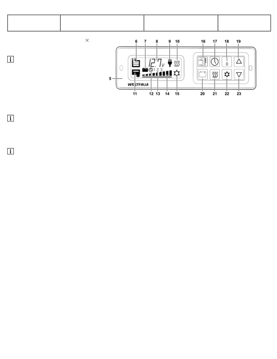
Carry out self-test for battery
voltage button


1 Press the down button (23) 13 

 Within 60 seconds after the

central electronics (5) is in self-
test mode 

2 Press battery voltage button
(20). 

3 Check of multiple display (8). 

 If OK is displayed in the

multiple display (8), this means
that the battery voltage button
(20) is OK. 

 If F is displayed in the multiple

display (8), this means that the
battery voltage button (20) has a
fault.


D54.21-1125-04

AR54.21-D-0021-
14A

Carry out self-test for timer
button


1 Press the down button (23) 14 

 Within 60 seconds after the

central electronics (5) is in self-
test mode 

2 Press timer button (17). 

3 Check of multiple display (8). 

 If OK is displayed in the

multiple display (8), this means
that the timer button (17) is OK. 

 If F is displayed in the multiple

display (8), this means that the
timer button (17) has a fault.


D54.21-1125-04

AR54.21-D-0021-
15A

Carry out self-test for heater
button


1 Press the down button (23) 15 

 Within 60 seconds after the

central electronics (5) is in self-
test mode 

2 Press heater button (21). 

3 Check of multiple display (8). 

 If OK is displayed in the

multiple display (8), this means
that the heater button (21) is OK. 

 If F is displayed in the multiple

display (8), this means that the
heater button (21) has a fault.


D54.21-1125-04

AR54.21-D-0021-
16A

Carry out self-test for ON-OFF
button


1 Press the down button (23) 16 

 Within 60 seconds after the

central electronics (5) is in self-
test mode 

2 Press ON-OFF button (18). 

3 Check of multiple display (8). 

 If OK is displayed in the

multiple display (8), this means
that the ON-OFF button (18) is
OK. 

 If F is displayed in the multiple

display (8), this means that the
ON-OFF button (18) has a fault.


D54.21-1125-04

AR54.21-D-0021-
17A

Carry out self-test for refrigerator
button, refrigerator box button


1 Press the down button (23) 17 

 Within 60 seconds after the

central electronics (5) is in self-
test mode 

2 Press refrigerator box button,
refrigerator button (22). 

3 Check of multiple display (8). 

 If OK is displayed in the

multiple display (8), this means
that the refrigerator box button,
refrigerator button (22) is OK. 

 If F is displayed in the multiple

display (8), this means that the
refrigerator box button,
refrigerator button (22) has a fault.


D54.21-1125-04

AR54.21-D-0021-
18A

n Carry out self-test for up button  


1 Press the down button (23) 18 

 Within 60 seconds after the

central electronics (5) is in self-
test mode 

2 Press UP button (19). 

3 Check of multiple display (8). 

 If OK is displayed in the

multiple display (8), this means
that the UP button (19) is OK. 

 If F is displayed in the multiple

display (8), this means that the
UP button (19) has a fault.


D54.21-1125-04

AH54.00-P-1000-
01A

Evaluating electronic
components after repair and
painting work and after accidents

All models

1. With paint drying in drying oven 
Electronic components, such as the switching unit
for the ignition system, the control unit for the
electronic fuel/diesel injection system, the ABS
system, airbag, emergency tensioning retractors
etc. may only be heated up to an object
temperature of maximum 90 °C. 

In cases of doubt the temperature at these points
should be checked by a series of measurements
(remove electronic components beforehand) by
means of a mercury maximum thermometer during
the baking phase. 

If the maximum permissible temperature is not
exceeded, the electronic components need not be
removed. 

No particular safety measures are required at an
object temperature up to max. 60 °C (air injection
temperature max. 
90 °C). 


2. With welding 
Always disconnect and cover the negative terminal
of the battery. Disconnect airbag 10-pin data link
connector (color red) in the right footwell after
waiting for 2 seconds after disconnecting the
battery or as of 07/93 detach the coupling on the
airbag control unit using the insertion and removal
aid. 

3. After accidents 
Replacing electronic control units after an accident
is only necessary if at least one of the following
conditions is met: 

 The housing is recognizably deformed or

damaged. 

 The contact surface or bearing bracket is

deformed; externally the unit does not appear
damaged. 

 The connector is damaged or corroded by

moisture. 

 Faults are established by a function test or self-

diagnosis of the unit. 

 If electronic components, such as the ABS

control unit, have been removed for repair and are
then used again, these should be checked for
proper operation after assembly. 

Read fault memory and erase


AH00.00-N-0001-
01A

Notes on self-locking nuts and
bolts

All models

Important repair information 

 Bolts with locking splines, micro-encapsulated

bolts and self-locking nuts must always be replaced
after being used once. 

There is an increased risk of injury when
unscrewing micro-encapsulated bolts due to the
sudden breakaway torque.


Before new micro-encapsulated bolts are screwed
in, the mating thread must be re-cut in order to
remove all the residue of the old bolt locking
compound.


Content   ..  64  65  66  67   ..