Westfalia. Testing repair electrical manual - part 43
 

  Index      Westfalia     Westfalia (903.662) testing repair electrical manual in english


Search            copyright infringement  


Content   ..  41  42  43  44   ..


Westfalia. Testing repair electrical manual - part 43


D86.60-0018-11

Remove


1

Remove strainer (1) from waste
trap (2)


2

Remove caps (3)


3

Remove bolts (4)


4

Remove covers (5)


5

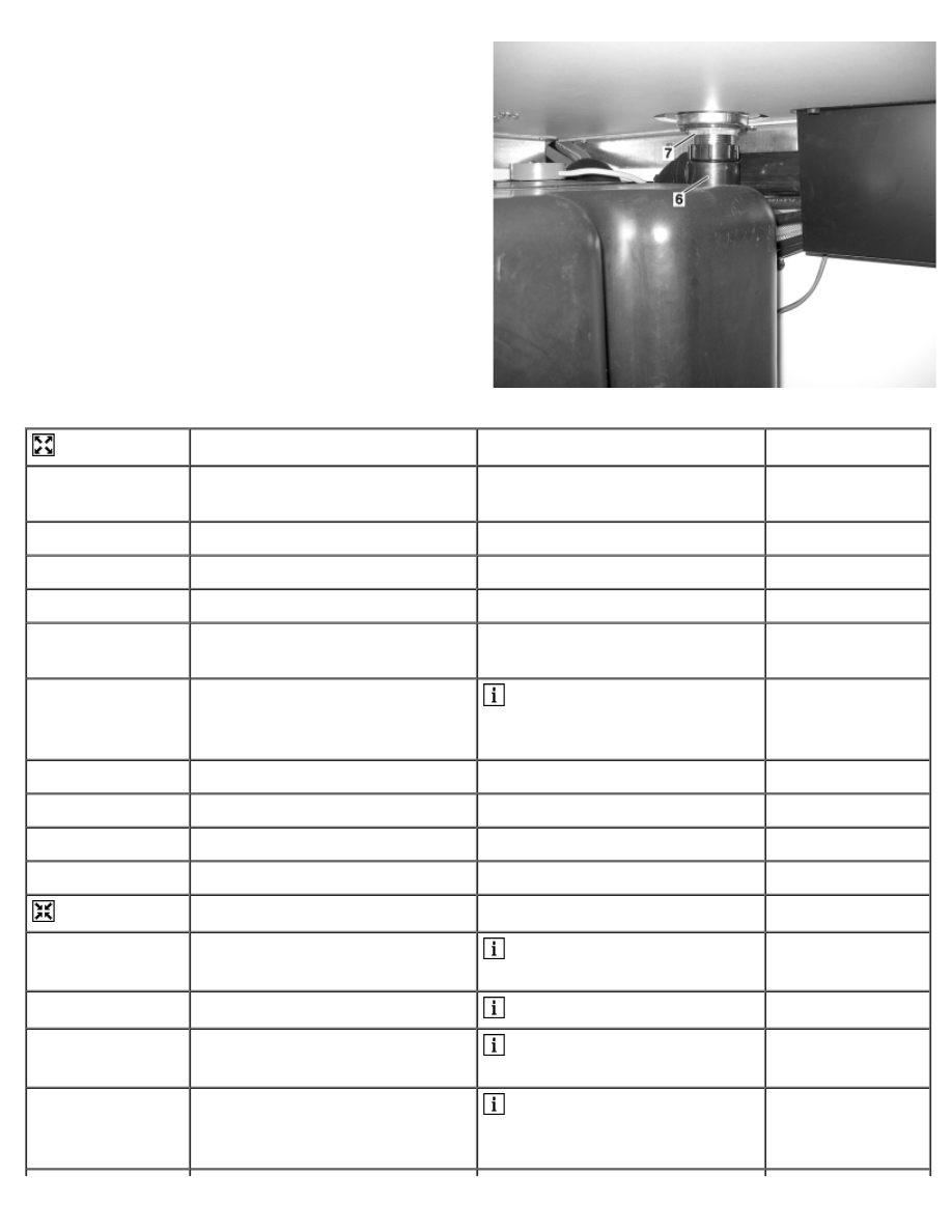
Unscrew downpipe (6) as far as
possible


6

Unscrew nut (7)

 Helper must hold waste trap

(2) in sanitary block with suitable
tool.


7

Press waste trap (2) upward


8

Unscrew downpipe (6)


9

Unscrew nut (7)


10

Remove waste trap (2)


Install


11

Insert waste trap (2)

 Check seals for damage,

replace if necessary


12

Screw on nut (7)

 Screw on only half of thread


13

Screw on downpipe (6)

 Check seals for damage,

replace if necessary


14

Tighten nut (7)

 Helper must hold waste trap

(2) in sanitary block with suitable
tool.


15

Check downpipe (6) for leakage


16

Insert covers (5)


17

Screw in bolts (4)


18

Position caps (3)


19

Insert sieve (1)


AR86.60-D-0073A

Remove/install sanitary block wash basin water tap

12.5.04

MODEL  903.662


with CODE (ZU8) National version for USA


with CODE (Z29) "James Cook" touring camper, NAFTA

1 Hose clamps 
2 and hoses 
3 Screw 
4 Hose guide 
5 Nut 
6 Water tap 
7 Sealing ring 
8 Thread


D86.60-0087-06


Remove/Install


 Danger!

Risk of injury caused by hot
water exiting from the lines of the
fresh water system

Shut off the water heater in a
timely manner before starting
repair work. Let the water in the
lines and in the components of
the fresh water system cool
down to room temperature.

AS86.00-Z-0002-
01A

1

Remove wash basin in sanitary
block


AR86.60-D-
0009A

2

Slacken hose clamps (1)

 Installation: Replace hose

clamps (1).


3

Disconnect hoses (2)


4

Remove bolt (3)


5

Remove hose guide (4)


6

Separate hose connection
(arrow)

 Installation: Check hose


connection seal for damage,
replace if necessary to prevent
leakage

7

Unscrew nut (5)


8

Remove water tap (6)

 Installation: Check sealing

ring (7) and thread (8) for
damage, replace if necessary to
prevent leakage


9

Install in the reverse order


10

Check water tap (6) for proper
function


11

Check fresh water system for
proper function


AR86.30-D-
0065A

AR86.60-D-0085A

Remove/install gas shut-off cock

25.5.04

MODEL  903.662


with CODE (ZU8) National version for USA


with CODE (Z29) "James Cook" touring camper, NAFTA

1 Gas line 
2 Gas line 
3 Gas line 
4 Gas shut-off cock


D86.60-0091-05


Remove/install


 Danger!

Risk of explosion caused by
ignition of gas exiting the lines of
the vehicle's gas system. Risk of
injury
 caused by burns to skin
and eyes.

Before commencing any work,
ensure that all sources of ignition
have been removed and that the
gas system is completely
emptied if necessary. Wear
protective clothing.

AS86.00-Z-0004-
01A

1

Close main shut-off valve on
compressed gas reservoir

 See Operator's Manual


2

Unscrew gas lines (1, 2, 3) from
gas shut-off valve (4)


3

Remove gas shut-off valve (4)


4

Install in the reverse order


5

Perform leakage test for gas
system


AR86.60-D-
0100A

AR86.60-D-0100A

Perform leakage test for gas system

19.5.04

MODEL  903.662


with CODE (ZU8) National version for USA


with CODE (Z29) "James Cook" touring camper, NAFTA

Check


 Danger!

Risk of explosion caused by
ignition of gas exiting the lines of
the vehicle's gas system. Risk of
injury
 caused by burns to skin
and eyes.

Before commencing any work,
ensure that all sources of ignition
have been removed and that the
gas system is completely
emptied if necessary. Wear
protective clothing.

AS86.00-Z-0004-
01A

1

Close valves on gas cocker and
hot water boiler

 See Operator's Manual


2

Fill compressed gas reservoir

 See Operator's Manual


3

Open main shut-off valve on
compressed gas reservoir

 See Operator's Manual


4

Open shut-off vales for gas
cooker and hot water boiler

 See Operator's Manual


5

Spray gas lines, their
connections and components of
gas system with soapy water


6

Check gas lines, connections
and components of gas system
for leakage

 If a sufficient quantity of soap

solution is applied, bubbles are
present at leaky points.


7

Repair affected components or
replace


8

Repeat steps 1 to 6


AR86.60-D-0110A

Remove/install compressed-gas tank

26.5.04

MODEL  903.662


with CODE (ZU8) National version for USA


with CODE (Z29) "James Cook" touring camper, NAFTA

D86.60-0103-09

1 Main shut-off valve 
2 Gas line 
3 Reducer


4 Compressed-gas tank 
5 Nuts 
6 Nuts


7 Bracket 
8 Bracket


Remove/Install


 Danger!

Risk of explosion caused by
ignition of gas exiting the lines of
the vehicle's gas system. Risk of
injury
 caused by burns to skin
and eyes.

Before commencing any work,
ensure that all sources of ignition
have been removed and that the
gas system is completely
emptied if necessary. Wear
protective clothing.

AS86.00-Z-0004-
01A

Notes on self-locking nuts and
bolts

All models

AH00.00-N-0001-
01A

1

Drain compressed-gas tank (4)


2

Close main shut-off valve (1) on
compressed-gas tank (4)

 See Operator's Manual


3

Disconnect gas line (2) from


reducer (3)

4

Unscrew nuts (5) on both sides
of compressed-gas tank (4)

 Installation: Replace self-

locking nuts (5).


5

Unscrew nuts (6) on both sides
of compressed-gas tank (4)

 Installation: Before

tightening nuts (6) align
compressed-gas tank (4) with
reducer (4) parallel to gas line (2)


6

Remove bracket (7) on both
sides of compressed-gas tank
(4)


7

Remove compressed-gas tank
(4) from bracket (8) on both sides

 Helper required.


 When replacing compressed-

gas tank (4) transfer following
components: 


Remove/install cover for
compressed-gas tank

AR86.60-D-
0120A


Remove/install fill level sensor
for 
compressed-gas tank

AR86.60-D-
0130A


On compressed-gas tank


Remove/install pressure
reducing valve on compressed-
gas tank (4)

AR86.60-D-
0140A

8

Install in the reverse order


9

Perform leakage test for gas
system


AR86.60-D-
0100A


Content   ..  41  42  43  44   ..