Snowmobile Polaris 650 Pro RMK 155 / 650 RMK Khaos 146 Slash / 850 Pro RMK 155. Owner’s Manual (2024) - page 6
 

  Index      Manuals     Snowmobile Polaris 650 Pro RMK 155 / 650 RMK Khaos 146 Slash / 850 Pro RMK 155. Owner’s Manual (2024)


Search            copyright infringement  


Content      ..     4      5      6      7     ..


Snowmobile Polaris 650 Pro RMK 155 / 650 RMK Khaos 146 Slash / 850 Pro RMK 155. Owner’s Manual (2024) - page 6


Check skags before each use of the snowmobile to ensure positive steering
characteristics. Skags must be replaced when worn to half their original
diameter. Replace if carbide is damaged or worn away.

TIP

Carbide skags must be replaced if any abnormal wear or chipping is found.

SKAG REPLACEMENT

WARNING

Worn skis and/or skags will adversely affect handling. Loss of vehicle control

may result, causing serious injury or death. See your authorized POLARIS

dealer's studding chart for recommended skags. If you install longer or more

aggressive carbide skags than the original equipment, it may also be

necessary to add track studs to maintain proper vehicle control while turning

on hard-packed snow or ice.

NOTICE

Always replace ski skags in pairs.

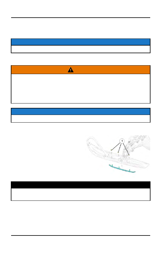
To replace ski skags, do the following:

1. Raise and support the front of the

snowmobile so the skis are
approximately 6 inches (15.2 cm)
from the ground.

2. Remove the attaching nuts

q

and

pry the skag downward.

3. Reverse the steps to install a skag.

Tighten nuts to specification.

TORQUE

Ski Skag Nuts

7 ft-lbs (10 N·m)

164

MAINTENANCE

RAIL SLIDE WEAR INSPECTION

Polaris rail slides

q

run along the bottom of the rail to prevent track wear. The

rail slide should be inspected periodically and replaced when necessary.

For ease of inspection, all POLARIS rail slides have a wear limit indicator groove

w

to indicate the minimum permissible slide thickness

q

. Replace the rail slides

if they are worn to the top of the groove at any point along their length. Failure to
do so may result in permanent damage to the track or rails.

165

MAINTENANCE

BATTERY MAINTENANCE

Keep battery terminals and connections free of corrosion. If cleaning is
necessary, remove the corrosion with a stiff wire brush. Wash with a solution of
one tablespoon baking soda and one cup water. Rinse well with tap water and
dry off with clean shop towels. Coat the terminals with dielectric grease or
petroleum jelly.

WARNING

CALIFORNIA PROPOSITION 65 WARNING:

Batteries, battery posts, terminals and related accessories can expose you to

chemicals including lead, which is known to the State of California to cause

birth defects or other reproductive harm. For more information go to www.

P65Warnings.ca.gov.

WARNING

Battery electrolyte is poisonous. It contains sulfuric acid. Serious burns can

result from contact with skin, eyes or clothing. Antidote:

External:

Flush with water.

Internal:

Drink large quantities of water or milk. Follow with milk of

magnesia, beaten egg, or vegetable oil. Call physician immediately.

Eyes:

Flush with water for 15 minutes and get prompt medical attention.

Batteries produce explosive gases.

Keep sparks, flame, cigarettes, etc. away. Ventilate when charging or using in

an enclosed space. Always shield eyes when working near batteries.

KEEP OUT OF REACH OF CHILDREN.

BATTERY IDENTIFICATION

It is important to properly identify the type of battery installed in your snowmobile
as different battery types require different service procedures. Proper servicing
and battery maintenance is crucial for battery longevity.

The four types of batteries are:

• Lead Acid Conventional
• Dry Shipped Absorbed Glass Mat (AGM)
• Lead Acid Low Maintenance
• AGM Low Maintenance

Refer to the following examples to identify the type of battery in your vehicle.

166

MAINTENANCE

LEAD ACID CONVENTIONAL AND DRY SHIPPED AGM
BATTERIES

These batteries are characterized by the following features:

• Battery is NOT activated when packaged
• Removable cap plugs and strip are found top-side of the battery

Lead Acid Conventional batteries ONLY:

Distilled water is added, as needed

Vent tube is located on the side of the battery

LOW MAINTENANCE BATTERIES

Low maintenance batteries are characterized by the following features:

• Battery is pre-activated when packaged
• Non removable cap(s) is located top-side of the battery
• Distilled water or electrolyte is NEVER added

167

MAINTENANCE

BATTERY REMOVAL (ELECTRIC START MODELS)

WARNING

Improperly connecting or disconnecting battery cables can result in an

explosion and cause serious injury or death. When removing the battery,

always disconnect the negative (black) cable first. When reinstalling the

battery, always connect the negative (black) cable last.

1. Remove the right side panel

to access the battery.

2. Remove the plastic rivet

securing the console panel to
the chassis.

3. Disconnect the black (negative) battery cable first.

4. Disconnect the red (positive) battery cable last.

5. Remove the battery hold-down strap.

6. Remove the battery shield

q

.

Non-Boost Models

Boost Models

7. Remove the battery from the battery bracket.

BATTERY INSTALLATION

When installing a new battery, make sure it's fully charged prior to its initial use.
Using a new battery that has not been fully charged can damage the battery and
result in a shorter life. It can also hinder vehicle performance. Follow the battery
charging instructions before installing the battery.

168

MAINTENANCE

1. Ensure that the battery is fully charged.

2. Set the battery in the battery holder.

3. Place the battery shield on the battery bracket.

4. Install the battery hold-down strap.

5. Connect and tighten the red (positive) cable first.

6. Connect and tighten the black (negative) cable last.

CAUTION

Verify the battery cables and wiring harness do not come into contact with the

brake disc. Move the wiring harness/cables behind the chassis tube and away

from the brake disc.

7. Route the BROWN harness ground wires

q

and BLACK main battery

ground cable

w

as shown in the image. Both are routed up and over the

rubber strap. If the ground wires/cable are routed down the side of the
battery, they may interfere with the rear side panel tab. Note the routing of
the RED (positive) battery cable

e

and that the right fender is pulled away

from the chassis. Item

r

is the constant power fuse connector.

8. Verify that cables are properly routed.

NOTICE

Ensure that the battery wires are routed in such a way that they cannot come

into contact with the brake disc.

169

MAINTENANCE

9. Secure the right fender using the plastic rivet.

10. Reinstall the console using the two plastic rivets. Reinstall the side panel.

BATTERY CHARGING

To ensure your battery maintains its level of charge, the battery should be
connected to a battery trickle charger using the battery charge port

q

.

1. Check the battery voltage with a

voltmeter or multimeter. A fully
charged battery will register 12.8 V
or higher.

2. If the voltage is less than 12.8 volts,

recharge the battery at 1.2 amps or
less until the battery voltage is 12.8
or greater using the battery charge
port

q

.

RESTRICTION

When using an automatic charger, refer to the charger manufacturer's

instructions for recharging. When using a constant current charger, use the

following guidelines for recharging.

WARNING

An overheated battery may explode, causing severe injury or death. Always

watch charging times carefully. Stop charging if the battery becomes very

warm to the touch. Allow it to cool before resuming charging.

TIP

Always verify battery condition before and 1-2 hours after the end of charging.

State of Charge

Voltage

Action

Charge Time*

100%

12.8-13.0 volts

None, check at 3 mos.
from date of
manufacture

None required

75%-100%

12.5-12.8 volts

May need slight
charge, if no charge
given, check in 3
months

3-6 hours

50%-75%

12.0-12.5 volts

Needs charge

5-11 hours

170

MAINTENANCE

25%-50%

11.5-12.0 volts

Needs charge

At least 13 hours,
verify state of charge

0%-25%

11.5 volts or less

Needs charge with
desulfating charger

At least 20 hours

*Using constant current charge @ standard amps specified on top of battery.

BATTERY CHARGE RELAY CONTROL

Some models are equipped with a battery. The battery provides power for only
two purposes:

• Engaging the electric starter motor to start the engine
• Powering the 7S Display with the ignition key when the engine is off

The engine management system turns on the battery charge relay and charges
the battery only when the following conditions are met:

• The load shed relay is turned on by the engine management system
• Engine speed exceeds 2500 RPM
• Chassis DC voltage exceeds 13 volts

BATTERY MAINTENANCE

Keep battery terminals and connections free of corrosion. If cleaning is
necessary, remove the corrosion with a stiff wire brush and wash with a solution
of one tablespoon baking soda and one cup water. Rinse well with tap water and
dry off with clean shop towels. Coat the terminals with dielectric grease or
petroleum jelly to prevent corrosion.

Never store a battery in a partially charged condition or hard, crystal sulfation will
form on the plates resulting in reduced efficiency and shorter service life of the
battery.

If you do not drive the vehicle for more than TWO weeks, maintain Absorbent
Glass Mat (AGM) batteries with the BatteryMINDer® 2012 AGM - 2 AMP
charger (or a similar charger).

BatteryMINDer® 2012 AGM - 2 AMP battery charger

PN 2830438

If you plan to store the vehicle for ONE month or longer, remove the battery from
the vehicle and store in a cool, dry location. Batteries will self-discharge more
rapidly when stored in extreme temperatures. Continue to maintain the battery
with a 2-AMP charger and inspect the battery every 60 days.

171

MAINTENANCE

BATTERY TYPE

RECHARGE
FREQUENCY

GENERAL MAINTENANCE

Lead Acid
Conventional

Every 30 to 60 days

NEVER add electrolyte to the
battery once the battery is in
service. If necessary, only add
distilled water to the battery.

Dry Shipped AGM

Inspect every 60 days

NEVER add electrolyte or
distilled water to the battery
once the battery is in service.

Lead Acid Low
Maintenance

Every 30 to 60 days

NEVER add electrolyte or
distilled water to the battery.
Doing so will damage the case
and shorten the life of the
battery.

AGM Low
Maintenance

Inspect every 60 days

NEVER add electrolyte or
distilled water to the battery.
Doing so will damage the case
and shorten the life of the
battery.

TRANSPORTING THE SNOWMOBILE

Whenever the snowmobile is transported:

1. Be sure the fuel cap and oil cap are installed correctly.

2. Tie the snowmobile to the transporting unit securely using suitable straps.

3. Remove the ignition key to prevent loss.

NOTICE

Use of a cover is recommended when transporting your vehicle on an open

trailer or sled deck.

172

MAINTENANCE

SUMMER/LONG-TERM STORAGE GUIDE

TREATING THE FUEL SYSTEM

As the riding season draws to a close, Polaris recommends riders begin treating
their snowmobile’s fuel system with Polaris Carbon Clean or similar
commercially-available fuel stabilizer.

Treating the fuel system with Carbon Clean during the last few rides of the
season ensures the entire fuel system is treated. Then, when it comes time to
store the snowmobile, all the rider has to do is completely fill the fuel tank with
fresh, non-oxygenated fuel and treat the new fuel with Carbon Clean.
It is also recommended riders use non-oxygenated fuel during the last rides of
the season as non-oxygenated fuel stores better than oxygenated fuel and
resists water vapor absorption.
If the rider was unable to treat the fuel system and/or use non-oxygenated fuel at
the end of the riding season, the rider should do the following:

1. The rider should consume as much fuel in the fuel tank as possible during

the last rides of the season.

2. When performing the summerization storage procedures, fill the fuel tank

completely with non-oxygenated fuel. Note that most oxygenated fuels
contain ethanol. Since ethanol is hydroscopic, oxygenated fuel will absorb a
small amount of water vapor during the storage season and more so in
humid locations. Completely filling the tank with non-oxygenated fuel
minimizes water vapor absorption during the storage period and limits the
amount of air and water vapor that can accumulate in the tank.

3. Treat the fuel in the fuel tank with the recommend amount of Polaris Carbon

Clean. The recommended mixing ratio is outlined on the bottle label.

4. Position the snowmobile outside in a well-ventilated area.

5. Start and run the engine for 10-15 minutes to distribute the treated fuel

throughout the fuel system.

NOTICE

On Carbureted engines (550cc / 120 Youth), run the engine for 10-15 minutes

and then turn the fuel shut off valve to ‘OFF’. Continue to run the engine until

the engine stalls and turns off. Doing this drains the carburetors of fuel.

173

MAINTENANCE

FOGGING THE ENGINE

Fogging the engine with Polaris fogging oil or similar commercial alternative is
probably the most important storage step a rider can do to ensure the internal
parts of their snowmobile’s engine do not rust and corrode during the storage
season.

To fog the engine, do the following:

1. Remove the spark plugs from the engine.

2. Liberally spray fogging oil into each spark plug hole. If possible, have an

assistant slowly pull on the recoil rope to rotate the engine while spraying the
oil into each cylinder.

3. Loosely install the spark plugs.

NOTICE

Do not install new spark plugs after fogging the cylinders. Fogging oil prevents

the formation of rust / corrosion by sticking to the internal engine components –

including the spark plug electrodes. Replace these spark plugs the following

season after all of the fogging oil has been burned out of the engine.

DRIVE BELT STORAGE

Never leave the drive belt installed in the clutches as oxidation may form where
the belt contacts the aluminum clutch sheave faces.

To clean the drive and driven clutches, do the following:

1. Remove the primary and spare drive belt from the snowmobile.

2. Inspect the drive belt for wear and glazing. Compare the primary belt with the

spare belt. Decide if a new belt is needed next season and note the primary
belt can now be used as the spare belt next season.

3. Clean the drive and driven clutch sheaves with Isopropyl Alcohol. Allow the

alcohol to air dry. Continue cleaning the sheave faces until all belt residue is
removed.

174

MAINTENANCE

BATTERY/ELECTRICAL SYSTEM STORAGE

Never leave a battery
unattended during the storage
season. Snowmobile batteries
are small and cannot maintain
their charge over the storage
season. To ensure your battery
maintains its level of charge, the
battery should be connected to a
battery trickle charger using the
battery charge port.

1. While the battery can remain installed on the snowmobile, it is recommended

the battery be removed from the snowmobile and stored in a cool, and dry
location. Removing the battery from the snowmobile facilitates off-site
storage of the snowmobile where electricity may not be available to connect
a battery charger. In addition, removing the battery allows access to other
maintenance items, such as the chaincase chain tensioner bolt.

2. Connect a Polaris battery charger or equivalent commercially available

charger to the battery.

3. Inspect the electrical connections and wire harnesses throughout the

snowmobile. If damage is found, make a note of the damage so that you and
your authorized Polaris dealer can address the concern.

CLEANING THE SNOWMOBILE

Snowmobiles, especially those transported on sled decks and open trailers can
accumulate a lot of water and road dirt / salt during the riding season. The
snowmobile must be thoroughly washed and cleaned to prevent corrosion and
rust formation.

Cleaning any Polaris snowmobile should ONLY be done with a mild soap and
water solution. Any cleaning, buffing or waxing products containing colorant dye
should be avoided. If using products with colorant dye in them, test on an
inconspicuous area of the bodywork before applying, as a dye may stain the
finish.

The deep gloss surfaces of Matryx snowmobiles are achieved through a
combination of Painted and Molded Nylon 6 material. Molded Nylon 6 delivers
improved strength and durability while providing a lustrous surface finish. With
proper care they will provide years of durable service.

175

MAINTENANCE

1. Wash the snowmobile with mild soap and water. Note that if a pressure

washer is used, care should be taken to not point the pressure washer
nozzle close to the snowmobile, which may force high pressure water into
suspension / shock shaft seals and exposed electrical connectors.

2. Dry the snowmobile with a lint-free towel. Allow the entire snowmobile to air

dry afterwards.

3. Clean the engine compartment. Use a shop vacuum if required to remove

dirt, leaves, cat tails, etc. from within the engine compartment.

4. If choosing to apply a cleaner, wax or polish, make sure it does not contain a

colorant dye and/or test on an inconspicuous area of the panel. Also make
sure the product is safe to use on Molded Nylon 6 material with or without a
painted finish.

5. Hand wash the exhaust system and dry the pipe and silencer with a clean

shop towel.

6. Apply “spray” metal protectant on exposed metal components, such as the

exhaust pipe, silencer, shock shafts, and suspension springs / pivots.

IMPORTANT

Do not spray metal protectant on the drive or driven clutches.

MOLDED NYLON 6 BODY PANELS

IMPORTANT

The use of a high speed/orbital polisher/buffer is not recommended on Molded

Nylon 6 components and could result in color fading.

176

MAINTENANCE

REFERENCE NUMBER

DESCRIPTION

q

Hood Trim, LH and RH

w

Console Trim, LH and RH

e

Side Panel Trim, LH and RH

r

Side Panels, LH and RH

t

Hood

LUBRICATE THE PIVOTS

After washing the snowmobile, it is important to use Polaris Premium All Season
grease to lubricate the various suspension / steering pivot points. Doing so
forces any water accumulated within the joints out which prevents the formation
of corrosion and rust.

1. Use a grease gun and Polaris Premium All Season Grease. Reference the

appropriate Owner’s Manual to locate any / all grease zerks on the steering
and suspension systems.

2. Pump fresh grease into all zerks until the grease can be seen purging out of

each joint.

3. Use a paper towel to clean up and remove all of the residual purged grease

from the joints.

177

MAINTENANCE

STORING THE SNOWMOBILE

Never store the snowmobile in a hot, humid location if possible. Try to store the
snowmobile away from direct sunlight.

1. Cover the snowmobile with a Polaris cover or after-market equivalent cover.

2. Store in a location away from water, tall grass, and direct sunlight. The

storage location should have some level of ventilation to prevent stagnant,
humid air from accumulating in and around the snowmobile.

WINTER RIDE PREPARATION

Preparing a snowmobile for in-season service is basically performing some of
the summer storage procedures in reverse order.

1. Move the snowmobile outside to a well-ventilated area. Raise the rear

suspension up, off the ground. Remove the engine compartment side panel
and hood.

2. Prep the primary and back up (secondary) belts for winter use. It is

recommended the belts be washed with a solution of warm, soapy water and
allowed to air dry.

3. If the snowmobile is equipped with electric start or a lightweight battery for

the 7S display, remove the battery from the battery charger and re-install it
back into the battery box. Follow the owner’s manual for battery installation
procedures.

4. Verify the spark plugs are installed and torqued. Re-install the spark plug

wires.

NOTICE

Verify you hear an audible “click” when pushing the spark plug caps down onto

the spark plugs. This ensures the plug caps are seated properly.

5. If you placed dryer sheets inside the engine compartment, remove them.

6. Using clean and dry shop towel, wipe down the exhaust pipe , silencer, and

clutch sheaves.

7. Install the primary drive belt onto the clutches with the “Polaris” writing

readable from the outside of the snowmobile.

8. Install the back-up (secondary) drive belt into the belt holder.

9. On carbureted snowmobiles, turn the fuel shut-off valve to the ON position.

10. With the track suspended up, off the ground, follow the track tension

adjustment procedure as outlined in your owner’s manual.

178

MAINTENANCE

11. Start and run the engine. Allow the engine to run for at least 15 minutes.

Occasionally “blip” the throttle to rev the engine.

NOTICE

The exhaust may emit more smoke than usual as the fogging oil is burned out

of the engine.

12. While the engine is running, verify there are no coolant leaks (on liquid

cooled engines). After engaging the throttle a few times to spin the track,
verify the track is aligned with the slide rails.

13. Turn off the engine. If the track requires, re-align the track at this time.

14. After adjusting the track or allowing the engine to cool down. Add coolant to

reservoir bottle if required.

15. Re-start the engine and allow it to run for another 15 minutes. After 15

minutes, shutoff the engine and allow the exhaust pipe to cool.

16. Remove and discard the spark plugs. Install new spark plugs into the engine.

Obtain two more new spark plugs and install them into the spark plug holders
or storage bag.

17. Inspect the ski wear bars/carbides. Now is the time to replace the wear bars

if damage if found or carbides are worn.

18. Add Carbon Clean to the fuel tank.

19. If equipped with a 7S Display, log onto www.ridecommand.com and

download the software.

20. Grease the rear suspension grease zerks with Polaris Premium All Season

grease just enough to push out any water that may have accumulated in the
suspension pivot points.

179

MAINTENANCE

180

SPECIFICATIONS

650 PRO RMK
650 RMK KHAOS

CAPACITIES AND DIMENSIONS

Body Style

Matryx

Rider Capacity

1

Coolant Capacity

650 PRO RMK 6.16 qt (5.83 L)
650 RMK Khaos 5.34 qt (5.05 L)

Chaincase Oil Capacity

N/A

Fuel Tank Capacity

11 gal (41.6 L)

Gearcase Oil Capacity

N/A

Oil Capacity

3.9 qt (3.7 L)

Disc Brake Type

RMK LWT

Drive Clutch Center Distance

11.5 in (29 cm)

Drive Belt P/N

3211115

Drive Clutch

P-85

Driven Clutch

LW Team Roller Reverse

Reverse Transmission

Electronic Reverse

181

SPECIFICATIONS

ENGINE AND COOLING

Engine

S9017-6544-LR6R

Displacement

650 cc

Cylinders

2-monoblock

Bore x Stroke (mm)

74.8 x 74

Alternator Output

500 w @ 5,000 RPM

Throttle Body

1208674

Oil Injection

Electronic Oil Pump

Recommended Engine Oil

VES

Throttle Body Bore Size

(50 mm)

Idle RPM

1800 +/- 200

Rated Operating RPM

8250 +/- 150

Cooling

Liquid

Thermostat Opening Temp.

98.6 °F (37 °C)

Ignition Type

CDI

Spark Plug / Gap

NGK® BPR 9ES / .027 in (.7 mm)

Recommended Fuel Octane

87 recommended

FEATURES

Electronic Fuel Gauge

Standard

Electric Start

Optional / Accessory

Low Oil Light

Standard

Parking Brake

Standard

Speedometer

Standard

Tachometer

Standard

182

SPECIFICATIONS

CLUTCHING CHART

CLUTCH SETTINGS

ALTITUDE

meters (feet)

DRIVE CLUTCH

DRIVEN CLUTCH

QUICK DRIVE

Gearing / Pitch

Shift

Weight

Clutch
Spring

Clutch
Spring

Driven

Helix

2.0 in &

2.6 in

Track

2.75 in

Track

0-900 (0-3000)*

10-66

(1321584)

BLACK/G-

RN

120-340

(7042083)

BLACK

155-222

(7043063)

58/44/.36

(5143872)

22:43

69 Pitch

22:50

73 Pitch

900-1500

(3000-5000)

10-64

(1321585)

1500-2100

(5000-7000)

10-62

(1321586)

BLACK /

GRN

120-340

(7042083)

BLACK

155-222

(7043063)

STR 42

(5143881)

2100-2700

(7000-9000)**

10-60

(1321587)

2700-3300

(9000-11,000)

10-58

(1321588)

3300-3900

(11,000-13,000)

10-56

(1321684)

Shaded cells indicate factory settings. Use 2 gram lighter shift weights when
operating in temperatures above 40° F (5° C).
* = North American Low-Elevation and INTL Stock Setting
** = North American High-Elevation Stock Setting

Drive Clutch Bolt Torque: 80 ft-lbs (108 Nm) Re-torque after running engine.

183

SPECIFICATIONS

850 PRO RMK
850 RMK KHAOS

CAPACITIES AND DIMENSIONS

Body Style

Matryx

Rider Capacity

1

Coolant Capacity

Short: 5.33 qt (5.05 L)
Long: 6.16 qt (5.83 L)

Chaincase Oil Capacity

N/A

Fuel Tank Capacity

11 gal (41.6 L)

Gearcase Oil Capacity

N/A

Oil Capacity

3.9 qt (3.7 L)

Disc Brake Type

RMK LWT

Drive Clutch Center Distance

11.5 in (29 cm)

Drive Belt P/N

3211216

Drive Clutch

P-85

Driven Clutch

LW Team Roller Reverse

Reverse Transmission

Electronic Reverse

184

SPECIFICATIONS

ENGINE AND COOLING

Engine

S9019-8544-LR8R

Displacement

840 cc

Cylinders

2-monoblock

Bore x Stroke (mm)

85 x 74

Alternator Output

500 w @ 5,000 RPM

Throttle Body

1208673

Oil Injection

Electronic Oil Pump

Recommended Engine Oil

VES

Throttle Body Bore Size

(50 mm)

Idle RPM

1800 +/- 200

Rated Operating RPM

8250 +/- 150

Cooling

Liquid

Thermostat Opening Temp.

98.6 °F (37 °C)

Ignition Type

CDI

Spark Plug / Gap

NGK® BPR 9ES / .027 in (.7 mm)

Recommended Fuel Octane

91 recommended (87 minimum)

FEATURES

Electronic Fuel Gauge

Standard

Electric Start

Optional / Accessory

Low Oil Light

Standard

Parking Brake

Standard

Speedometer

Standard

Tachometer

Standard

185

SPECIFICATIONS

CLUTCHING CHART

CLUTCH SETTINGS

ALTITUDE

meters (feet)

DRIVE CLUTCH

DRIVEN CLUTCH

QUICK DRIVE

Gearing / Pitch

Shift

Weight

Clutch
Spring

Clutch
Spring

Driven

Helix

2.0 in &

2.6 in

Track

2.75 in

Track

0-900 (0-3000)*

10-72

(1322428)

AL-

MOND/G-

LD

150-290

(7041645)

RED/BLU

140 - 200

(7043057)

60 / 44 /

.36

(5143882)

22:43

69 Pitch

22:50

73 Pitch

900-1500

(3000-5000)

10-70

(1322414)

1500-2100

(5000-7000)

10-70

(1322414)

BLACK

120-320

(7044537)

BLACK

155-222

(7043063)

STR 42

(5143881)

2100-2700

(7000-9000)**

10-68

(1322427)

2700-3300

(9000-11,000)

10-66

(1321584)

3300-3900

(11,000-13,000)

10-64

(1321585)

Shaded cells indicate factory settings. Use 2 gram lighter shift weights when
operating in temperatures above 40° F (5° C).
* = North American Low-Elevation and INTL Stock Setting
** = North American High-Elevation Stock Setting

Drive Clutch Bolt Torque: 80 ft-lbs (108 Nm) Re-torque after running engine.

186

SPECIFICATIONS

PATRIOT BOOST PRO RMK
PATRIOT BOOST RMK KHAOS

CAPACITIES AND DIMENSIONS

Body Style

Matryx

Rider Capacity

1

Coolant Capacity

Short: 5.41 qt (5.12 L)

Chaincase Oil Capacity

N/A

Fuel Tank Capacity

11 gal (41.6 L)

Gearcase Oil Capacity

N/A

Oil Capacity

3.9 qt (3.7 L)

Disc Brake Type

RMK LWT

Drive Clutch Center Distance

11.5 in (29 cm)

Drive Belt P/N

3211216

Drive Clutch Type

P-22

Driven Clutch

LW Team Roller Reverse

Reverse Transmission

Electronic Reverse

187

SPECIFICATIONS

ENGINE AND COOLING

Engine

S9038-8444-LR8M

Engine (International Models)

S9040-8444-LR8M

Displacement

840 cc

Cylinders

2-monoblock

Bore x Stroke (mm)

85 x 74

Alternator Output

500 w @ 5,000 RPM

Throttle Body

1208880

Oil Injection

Electronic Oil Pump

Recommended Engine Oil

VES Extreme

Throttle Body Bore Size

48 mm

Idle RPM

2000 +/- 200

Rated Operating RPM

8250 +/- 150

Cooling

Liquid

Thermostat Opening Temp.

98.6 °F (37 °C)

Ignition Type

CDI

Spark Plug / Gap

NGK® BPR 9ES / .027 in (.7 mm)

Recommended Fuel Octane

91 octane minimum

FEATURES

Electronic Fuel Gauge

Standard

Electric Start

Optional / Accessory

Low Oil Light

Standard

Parking Brake

Standard

Speedometer

Standard

Tachometer

Standard

188

SPECIFICATIONS

CLUTCHING CHART

CLUTCH SETTINGS

ALTITUDE

meters (feet)

DRIVE CLUTCH

DRIVEN CLUTCH

QUICK DRIVE

Gearing / Pitch

Shift

Weight

Clutch
Spring

Clutch
Spring

Driven

Helix

2.75 in

Track

3.25 in

Track

0-1500 (0-5000)*

14-80

(1327228)

BLK

165-310

(7045965)

BLK/PUR-

P

160-240

(7043363)

58 / 46 /

.36

(5144849)

22:43

69 Pitch

1500-3900

(5000-13,000)**

14-76

(1327226)

STR 46

(5144853)

22:50

73 Pitch

Shaded cells indicate North American and INTL stock settings. Use 2 gram lighter
shift weights when operating in temperatures above 40° F (5° C).
* = North American and INTL Low-Elevation Stock Setting
** = North American and INTL High-Elevation Stock Setting

Drive Clutch Bolt Torque: 110 ft-lbs (149 N·m). Re-torque after running engine.

189

SPECIFICATIONS

PATRIOT 9R PRO RMK
PATRIOT 9R RMK KHAOS

CAPACITIES AND DIMENSIONS

Body Style

Matryx

Rider Capacity

1

Coolant Capacity

Short: 5.33 qt (5.05 L)
Long: 6.16 qt (5.83 L)

Chaincase Oil Capacity

N/A

Fuel Tank Capacity

11 gal (41.6 L)

Gearcase Oil Capacity

N/A

Oil Capacity

3.9 qt (3.7 L)

Disc Brake Type

RMK LWT

Drive Clutch Center Distance

11.5 in (29 cm)

Drive Belt P/N

3211216

Drive Clutch Type

P-22

Driven Clutch

LW Team Roller Reverse

Reverse Transmission

Electronic Reverse

190

SPECIFICATIONS

ENGINE AND COOLING

Engine

S8886-9044-LR9B

Engine (International Models)

S9153–9044–LR9B

Displacement

899 cc

Cylinders

2-monoblock

Bore x Stroke (mm)

87.95 x 74

Alternator Output

500 w @ 5,000 RPM

Throttle Body

1208809

Oil Injection

Electronic Oil Pump

Recommended Engine Oil

VES

Throttle Body Bore Size

50 mm

Idle RPM

1800 +/- 200

Rated Operating RPM

8250 +/- 150

Cooling

Liquid

Thermostat Opening Temp.

98.6 °F (37 °C)

Ignition Type

CDI

Spark Plug / Gap

NGK® BPR 9ES / .027 in (.7 mm)

Recommended Fuel Octane

91 octane recommended (87 octane
minimum)

FEATURES

Electronic Fuel Gauge

Standard

Electric Start

Optional / Accessory

Low Oil Light

Standard

Parking Brake

Standard

Speedometer

Standard

Tachometer

Standard

191

SPECIFICATIONS

CLUTCHING CHART

CLUTCH SETTINGS

ALTITUDE

meters (feet)

DRIVE CLUTCH

DRIVEN CLUTCH

QUICK DRIVE

Gearing / Pitch

Shift

Weight

Clutch
Spring

Clutch
Spring

Driven

Helix

2.0 in &

2.6 in

Track

2.75 in &

3.25 in

Track

0-900 (0-3000)*

14-80

(1327228)

150-310

(7041922)

160-240

(7043363)

60 / 42 /

.36

(5144848)

22:43

69Pitch

22:50

73 Pitch

900-1500

(3000-5000)

14-78

(1327227)

1500-2100

(5000-7000)

14-74

(1327225)

140-330

(7043829)

56 / 42 /

.36

(5144803)

2100-2700

(7000-9000)**

14-72

(1323741)

2700-3300

(9000-11,000)

14-70

(1327224)

3300-3900

(11,000-13,000)

14-68

(1327223)

Shaded cells indicate North American and INTL stock settings. Use 2 gram lighter
shift weights when operating in temperatures above 40° F (5° C).
* = North American Low Elevation and INTL stock setting.
** = North American High Elevation stock setting.

Drive Clutch Bolt Torque: 110 ft-lbs (149 N·m). Re-torque after running engine.

192

SPECIFICATIONS

DIAGNOSTIC TROUBLE CODES (DTC)

DIAGNOSTIC TROUBLE CODES (DTCS)

DIAGNOSTIC TROUBLE CODES (DTCS) – MATRYX

SPN = SUSPECT PARAMETER NUMBER / FMI = FAILURE MODE INDICATOR

TROUBLE CODE

SPN

FMI

P-COD-

E

CONDITION

Throttle Position
Sensor 1 Voltage
High

51

3

P0123

This Trouble Code sets if the Throttle
Position Sensor Signal is above 4.61
Volts. Can be caused by Damaged Wiring,
a faulty Throttle Position Sensor or ECU /
Connections.

Throttle Position
Sensor 1 Voltage
Low

51

4

P0122

This Trouble Code sets if the Throttle
Position Sensor Signal is below 0.7 Volts.
Can be caused by Damaged Wiring, a
faulty Throttle Position Sensor or ECU /
Connections.

TPS Unrealistic
Transition

51

10

P0120

This Trouble Code sets when the Throttle
Position Sensor Signal changes too
rapidly to be correct. The condition can be
caused by intermittent connections
causing the TPS voltage to jump around
between readings. Check for damaged
connectors or wiring.

Vehicle Speed
Sensor Signal Fault

84

2

P0503

This Trouble Code Sets if the Vehicle
Speed Signal is intermittent or missing.
Can be caused by Damaged
Wiring/Connections or a Faulty/Loose
Vehicle Speed Sensor.

Intake Air Temp
Sensor Circuit
Voltage High

105

3

P0113

This Trouble Code sets if the Intake Air
Temperature Sensor Signal is above 4.9
Volts. Can be caused by Damaged Wiring,
a faulty Intake Air Temperature Sensor or
ECU / Connections.

Intake Air Temp
Sensor Circuit
Voltage Low

105

4

P0112

This Trouble Code sets if the Intake Air
Temperature Sensor Signal is below 0.19
Volts. Can be caused by Damaged Wiring,
a faulty Intake Air Temperature Sensor or
ECU / Connections.

IAT Sensor
Abnormal Rate of
Change

105

10

P0114

This Trouble Code sets if the Intake Air
Temperature Sensor Signal indicates an
Unrealistic Rate of Change. Can be
caused by Damaged Wiring, a faulty
Intake Air Temperature Sensor or ECU /
Connections.

Barometric Sensor
Circuit Voltage High

108

3

P2229

This Trouble Code Sets if the Barometric
Pressure Sensor Signal Circuit is Open or
Shorted to Battery Voltage. Can be

193

DIAGNOSTIC TROUBLE CODES (DTC)

DIAGNOSTIC TROUBLE CODES (DTCS) – MATRYX

SPN = SUSPECT PARAMETER NUMBER / FMI = FAILURE MODE INDICATOR

TROUBLE CODE

SPN

FMI

P-COD-

E

CONDITION

caused by Damaged Wiring/Connections,
a Faulty Ambient Pressure Sensor or
ECU.

Barometric Sensor
Circuit Voltage Low

108

4

P2228

This Trouble Code Sets if the Barometric
Pressure Sensor Signal Circuit is Shorted
to Ground. Can be caused by Damaged
Wiring/Connections, a Faulty Ambient
Pressure Sensor or ECU.

Engine
Temperature
Over-Temp
Shutdown

110

0

P1217

This Trouble Code sets if the Engine
Temperature indicates a Critical Over
Temperature Condition and the engine is
running in a limp-home mode to prevent
damage. Can be caused by any failure
that would cause the engine to overheat.

Engine
Temperature
Sensor Circuit
Voltage High

110

3

P0118

This Trouble Code sets if the Engine
Coolant Temperature Sensor Signal is
above 4.8 Volts. Can be caused by
Damaged Wiring, a faulty Coolant
Temperature Sensor or ECU /
Connections.

Engine
Temperature
Sensor Circuit
Voltage Low

110

4

P0117

This Trouble Code sets if the Engine
Coolant Temperature Sensor Signal is
below 0.1 Volts. Can be caused by
Damaged Wiring, a faulty Coolant
Temperature Sensor or ECU /
Connections.

Engine
Temperature
Abnormal Rate of
Change

110

10

P0119

This Trouble Code sets if the Engine
Coolant Temperature Sensor Signal is
erratic. Can be caused by Damaged
Wiring, a faulty Coolant Temperature
Sensor or ECU / Connections.

Engine
Over-temperature
Fault

110

16

P0217

This Trouble Code sets if the Engine
Temperature indicates a Severe Over
Temperature Condition. Can be caused by
any failure that would cause the engine to
overheat. This Trouble Code Does Not
indicate a problem with the Engine
Temperature Sensor.

Fuel Rail Pressure
Sensor Voltage
High

157

3

P0193

This trouble code sets if the Fuel Pressure
Sensor Voltage is above 4.85V. Can be
caused by Damaged Wiring, a faulty Fuel
Pressure Sensor or ECU / Connections.

194

DIAGNOSTIC TROUBLE CODES (DTC)

DIAGNOSTIC TROUBLE CODES (DTCS) – MATRYX

SPN = SUSPECT PARAMETER NUMBER / FMI = FAILURE MODE INDICATOR

TROUBLE CODE

SPN

FMI

P-COD-

E

CONDITION

Fuel Rail Pressure
Sensor Voltage
Low

157

4

P0192

This Trouble Code Sets if the Fuel
Pressure Sensor Circuit is below 0.1V.
Can be caused by Damaged Wiring, a
faulty Fuel Pressure Sensor or ECU /
Connections.

Fuel Rail Pressure
Below Power Limit

157

18

P0196

This Trouble Code Sets if the Fuel
Pressure drops below 3Bar (43.5PSI) for
10 seconds. Can be caused by a faulty
Pump Flange Assembly (PFA).

Battery Voltage
High

158

3

P1567

This Trouble Code Sets if the if the Battery
Voltage is above 15.0V. Can be caused by
Damaged Wiring, a faulty Battery or ECU /
Connections.

Battery Voltage
Low

158

4

P1566

This Trouble Code Sets if the if the Battery
Voltage is below 10.0V. Can be caused by
Damaged Wiring, a faulty Battery or ECU /
Connections.

Exhaust
Over-Temperature
Shutdown

173

0

P1517

This Trouble Code Sets if the engine was
shut down due to High Exhaust
Temperature. Can be caused by a Faulty
Exhaust Temperature
Sensor/Connections or Lean Air/Fuel
Ratio causing high exhaust temperature.

Exhaust Temp
Sensor Signal High

173

3

P0546

This Trouble Code sets if the engine has
been running above 3000 RPM for more
than 2 minutes and the Exhaust
Temperature Sensor Signal is above 4.90
Volts. Can be caused by Damaged Wiring,
a faulty Engine Temperature Sensor or
ECU / Connections.

Exhaust Temp
Sensor Signal Low

173

4

P0545

This Trouble Code sets if the engine has
been running above 3000 RPM for more
than 2 minutes and the Exhaust
Temperature Sensor Signal is below 0.06
Volts. Can be caused by Damaged Wiring,
a faulty Engine Temperature Sensor or
ECU / Connections.

Exhaust Temp
Sensor Unrealistic
Transition

173

10

P1546

This Trouble Code sets if the Exhaust
Temperature Sensor Signal changes too
quickly to be considered a Realistic Value.
Can be caused by Damaged Wiring, a
faulty Exhaust Temperature Sensor or
ECU / Connections.

195

DIAGNOSTIC TROUBLE CODES (DTC)


Content      ..     4      5      6      7     ..