Snowmobile Lynx CROSSOVER E-TEC SERIES. OPERATOR’S GUIDE (2023) - page 2
COMPACT DIGITAL DISPLAY
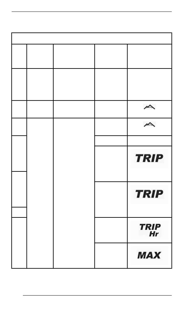
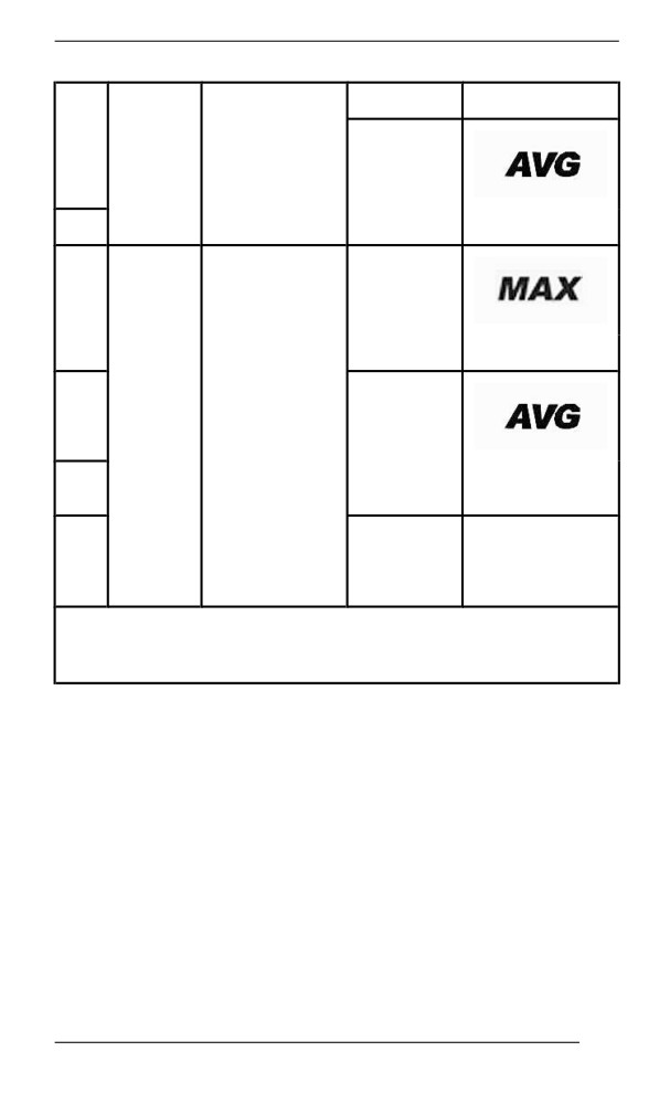
refer to the following table for available combinations.
Available Display Combinations
Icon/
Icon/
Upper
Lower
Specific
Specific
Display
Display
information
information
Vehicle
Vehicle
speed
Km/h or MPH
speed
Km/h or MPH
1
OR
OR
OR
OR
Engine
RPM
Engine
RPM
RPM
speed
Engine
RPM
Altitude
RPM
M or F
2
Altitude
M or F
Odometer
Km or MI
3
Trip
odometer
A(1)
Km or MI
4
Vehicle
Km/h or MPH
Trip
speed
odometer
B (1) (2)
5
Km or MI
Trip hour
(1)
6
Top speed
(1)
140
COMPACT DIGITAL DISPLAY
Km/h or MPH
7
Average
speed (1)
8
Km/h or MPH
Top RPM
9
(1)
RPM
10
Vehicle
Average
Km/h or MPH
speed
fuel
consump
tion
L/100Km or
11
MPG
Engine
coolant
E
12
tempera
and C or F
ture
(1) Press and hold the mode button to reset
(2) Resetting the trip odometer B also resets the average fuel
consumption
NOTE:
Make sure to display the vehicle speed whenever this information is
necessary.
141
COMPACT DIGITAL DISPLAY
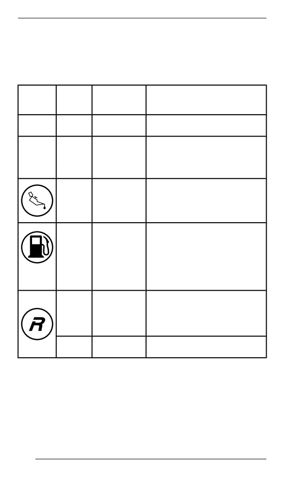
Icons and Messages
See table below for usual icons and messages.
For details on malfunction pilot lamps and messages, refer to Monitor-
ing System.
Message
Icon
Beeper
Lower
Description
Display
2 short
At power up, with a good key.
—
GOOD KEY
beeps
Vehicle ready for use.
Displayed during break-in
—
—
BREAK-IN
period. Refer to Break-in Period
4 short
beeps
Injection oil level is low. Stop
every
LOW OIL
vehicle in a safe place then,
5
replenish injection oil reservoir.
minutes
Low fuel level. No bar left in fuel
—
—
level display. Replenish fuel
tank as soon as possible.
(blink
ing)
Long
beeps
repeat
REVERSE
Reverse is selected.
ing
slowly
3 short
Reverse did not engage, try
REV. FAIL
beeps
again.
142

COMPACT DIGITAL DISPLAY
Message
Icon
Beeper
Lower
Description
Display
High beam headlights are
—
—
selected.
Engine and/or injection oil need
to warm-up before normal
operation. The engine's RPM is
limited until desired temperature
—
—
WARM UP
is reached
(up to
10 minutes
when driving). Warm-up period
may occur after a restart in very
cold weather.
143
GAUGE – 7.2” DIGITAL DISPLAY
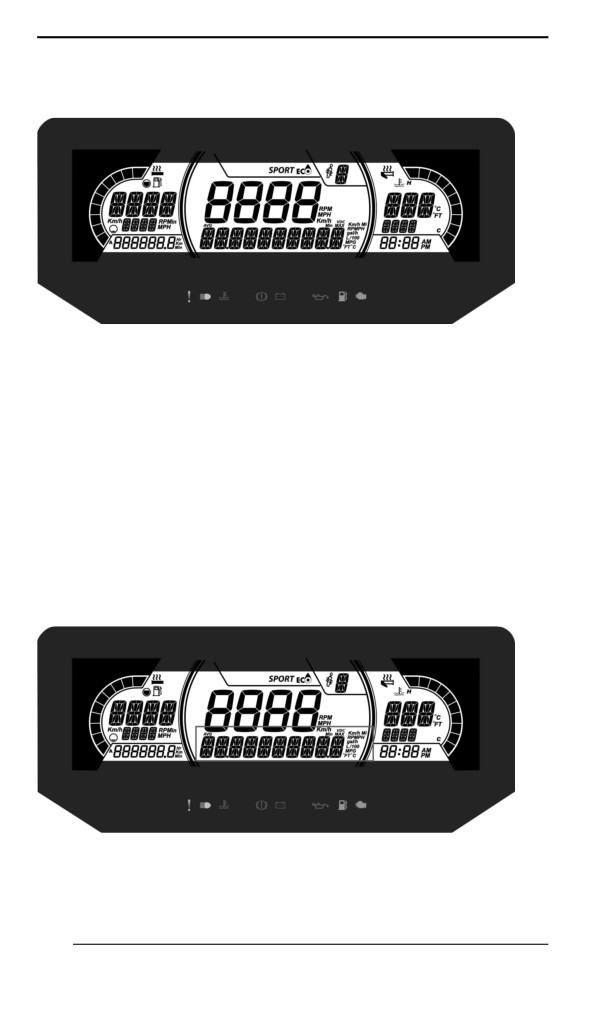
Mulltiifunction Diispllay
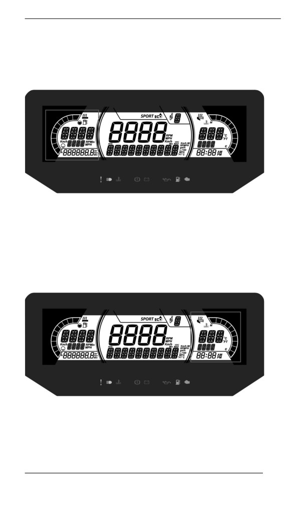
1. Select the upper or center display by using the MENU (M) button
on the multifunction switch. Refer to Secondary Controls for Menu/
Set button location.
2. While the desired display is flashing, navigate through the display,
by using the SET (S) button on the multifunction switch.
Once the desired information is displayed, press the MENU (M)
button or wait 5 seconds to confirm.
To reset
- Average speed
- Top speed
- Total fuel consumption
Press and hold the SET (S) button while display is flashing.
Lower Display
7.2" DIGITAL LOWER DISPLAY
May display the following:
- Settings
144
GAUGE - 7.2” DIGITAL DISPLAY
- Messages
The SPEED display shows the Maximum and the averaged speed.
Hold MENU button for 3 seconds to reset.
Left Lateral Display
The left lateral display includes:
- Fuel level indicator
- Heated Grip level
- Trip distance A and B (Km or mph)
- Cumulative hours
- Speed
- RPM
- Odometer
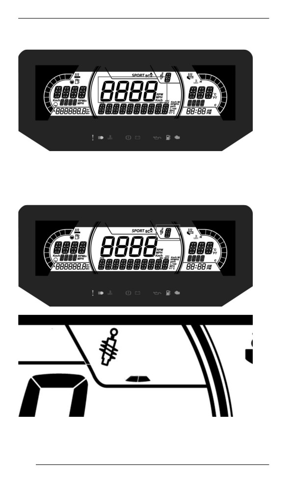
Right Lateral Display
The right lateral display includes:
- Engine Temperature
- Heated throttle indicator
- Clock
145
GAUGE - 7.2” DIGITAL DISPLAY
Central Display
Display the vehicle speed in Km/h (or MPH) or the RPMs. Refer to
Settings.
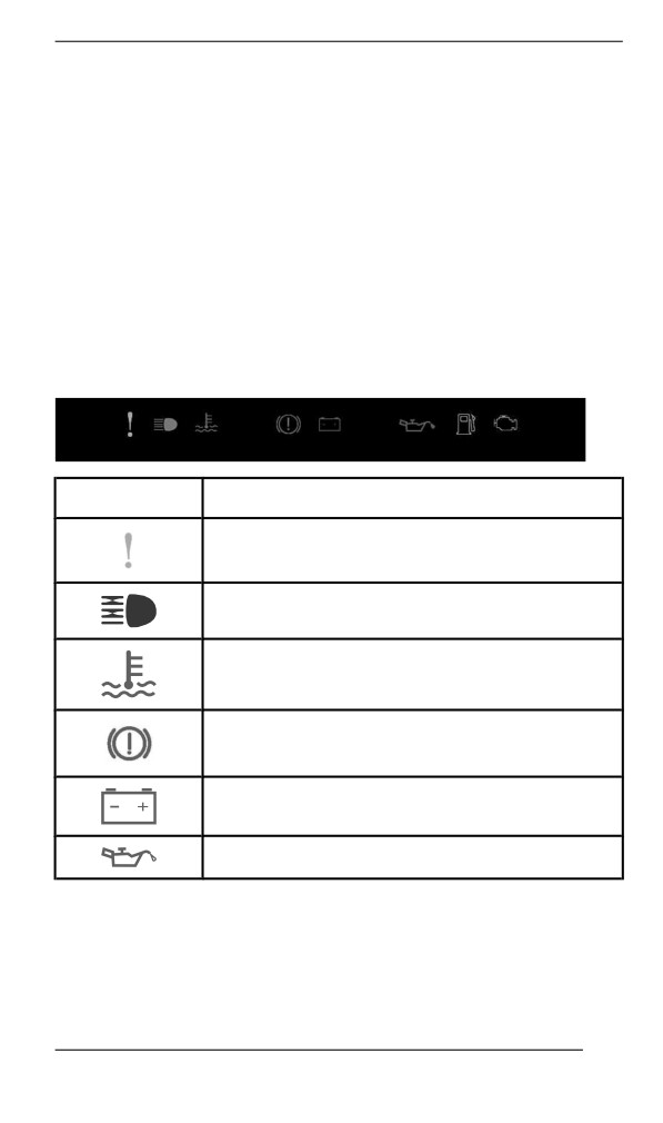
Smart-Shox Suspension Display (if equipped)
This icon appears and blinks when entering suspension mode selec-
tion or when suspension fault occurs.
146
GAUGE - 7.2” DIGITAL DISPLAY
Refer to TUNE YOUR RIDE section for selection procedure.
Warniing Lamps and Indiicators
The following indicator lamps will alert you to a vehicle condition that
may become serious. Some lamps will illuminate when starting the ve-
hicle to make sure they work. If any lamps remain on after starting the
vehicle, refer to the respective system warning lamp for further
information.
NOTE:
Some warning indicators appear in the display of the multifunction
gauge and function the same as an indicator lamp but do not display
when starting the vehicle.
Telltale Lights - Lower Bar
Lights
Description
ORANGE - Vehicle malfunction
BLUE - The high beam are selected
RED - The engine temperature is too high.
RED - Parking brake is engaged or malfunction
of the brake system
RED - The battery voltage too low or problem
with the electrical system
RED - Low injection oil level
147
GAUGE - 7.2” DIGITAL DISPLAY
Lights
Description
ORANGE - Low fuel level
ORANGE
Turn on: Malfunction of the vehicle emissions
control system
Blink: Engine problems, the limp home mode is
activated. Have the vehicle serviced
immediately.
Settings
Setup
Using MENU button, select SETTINGS and hold to enter setting
menu. Various options are available such as swapping the SPEED
and RPM in the Central Display.
Unit Selection
This multifunction gauge is factory preset in metric units but it is possi-
ble to change it to imperial units.
Using MENU button, select UNITS and hold button to change units.
Setting Clock
Using MENU button, select CLOCK and hold to change units.
1. Press MENU button to select clock display.
2. Push and hold MENU button for 1 second.
3. Press MENU button to select 12:00 AM PM or 24:00 time base.
4. Push and hold MENU button or OK button to acknowledge
selection.
5. Press MENU button to change hours (hours flash).
6. Push and hold MENU button or OK button to acknowledge hour
selection
7. Push MENU button to switch to minutes (minutes flash).
8. Press MENU button to change minutes.
Setting Language
The gauge display language can be changed. Refer to an authorized
BRP snowmobile dealer for language availability and to setup the
gauge to your preference.
148
GAUGE – 10.25” COLOR TOUCHSCREEN
DISPLAY
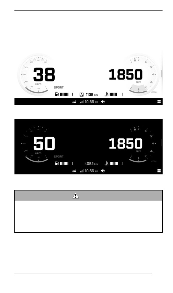
Default Diispllay
Light Mode
Dark Mode
Navigating the Digiitall Diispllay
WARNING
Reading or tampering with the multifunction gauge can distract
you from the operation of the vehicle, particularly from con-
stantly scanning the environment. Always pay attention to road
conditions, ensure your environment is clear and free from ob-
stacles. Furthermore, when riding, only glance at the multifunc-
tion gauge briefly to maintain awareness of road conditions.
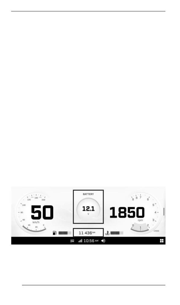
The multifunction gauge includes digital gauges (speedometer and
tachometer), indicator lamps and an infotainment center with a digital
screen.
149
GAUGE - 10.25” COLOR TOUCHSCREEN DISPLAY
We recommend you practice selecting some functions on the infotain-
ment center before getting on the road. You will get used to them and
they will be easier to use on the road.
Use the handlebar multifunction switch to navigate (touchscreen not
available when riding). Refer to Secondary Controls.
Pressing the Applet Switcher button on the handlebar multifunction
switch will make the modal view appear on top of the cluster.
Center Display
In full gauge view, long press in the upper center of the screen to show
one of the following extra gauges. Cycle through the extra gauges with
additional long presses.
- Battery voltage
- Coolant temperature
- Belt temperature (if equipped)
- Smart-Shox suspension type (if equipped)
- Altitude (if equipped)
- Ratio boost % (if equipped)
- Air suspension (if equipped)
In full gauge view, long press the lower center of the screen to show
one the following information. Cycle through the informations with ad-
ditional long presses.
- Vehicle total distance
- Trip A distance
- Trip A hours
- Trip B distance
- Trip B hours
- Vehicle total hours
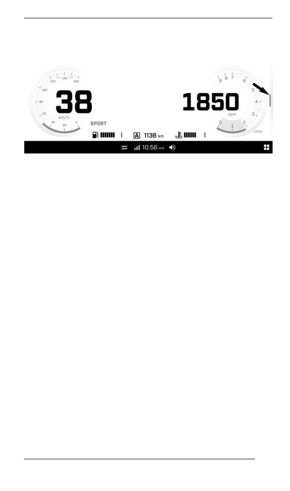
Narrow View Diispllay
To change from full gauge view to narrow view, open an applet or slide
the divider on the right side.
150
GAUGE - 10.25” COLOR TOUCHSCREEN DISPLAY
To change back to full gauge view, long press on Applet switcher or
slide the divider back in place.
The size of the left and right lateral displays cannot be adjusted.
Left Lateral Display
In narrow view, the left lateral display includes:
- Fuel level indicator
- Engine temperature
- Speedometer
- Tripmeter
- RPM
In narrow view, long press the speedometer to change the display be-
tween speedometer only or speedometer and RPM.
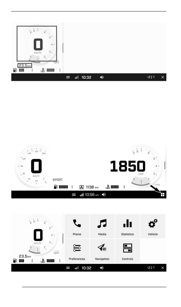
In narrow view, long press the tripmeter to show one of the following
information. Cycle through the informations with additional long
presses.
- Current ride distance
- Trip A distance
- Trip A hours
- Trip B distance
- Trip B hours
- Current ride hours
151
GAUGE - 10.25” COLOR TOUCHSCREEN DISPLAY
Right Lateral Display
In narrow view, the right lateral display includes various applet. Refer
to Applet Menu for more information.
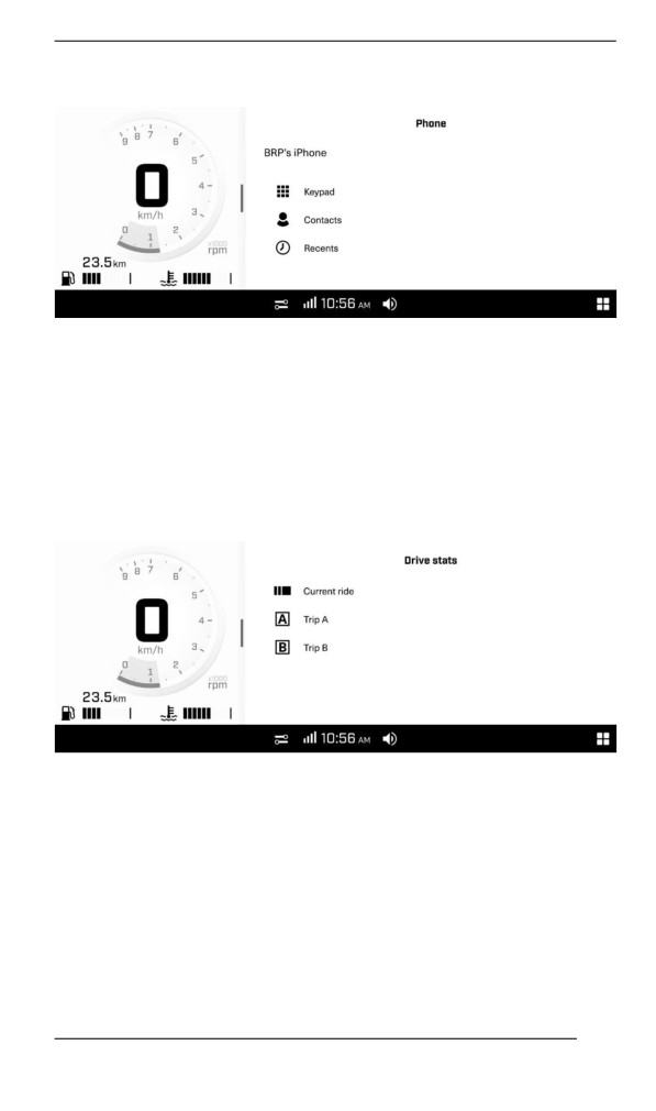
Appllet Menu
To access the applet menu, press the applet menu icon on the bot-
tom-right corner.
Press on an applet icon to open it.
152
GAUGE - 10.25” COLOR TOUCHSCREEN DISPLAY
Phone
The phone applet menu is to access:
- The keypad
- The phone contact list
- The phone history
NOTE:
To have access to the Phone menu, a phone and rider helmet (Head-
set) must be paired. Refer to Pair your Smartphone Via Bluetooth.
Statistics
The Statistics applet is used to get :
- Trip distance information
- Trip elapsed time information
- Average speed
3 sets of statistics are kept in memory. Trip A and Trip B can be reset
independently. Current ride statistic will be reset when the vehicle
restart.
153
GAUGE - 10.25” COLOR TOUCHSCREEN DISPLAY
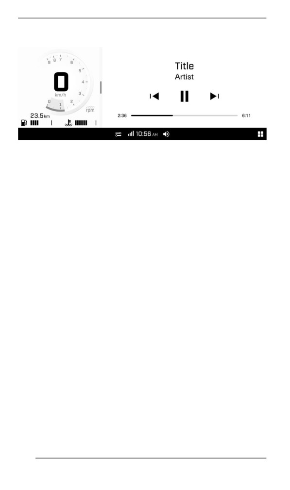
Media
The Media applet allows to manage music listened in the helmet audio
system.
Gives also song informations when available.
This vehicle is not equipped with speakers. An appropriate helmet
audio system is required to listen to music.
Preferences
The Preferences applet is to:
- Adjust the display brightness and appearance (Light/Dark/Auto)
- Pair Bluetooth devices:
- Phone
- Driver headset
- Passenger headset
- Connect vehicle to a Wi-Fi network
- Access General settings:
- Adjust the units (Imperial/Metric)
- Set the language
- Set the date and time
- Software update
- Get information about manufacturer information and device
regulatory compliance
- Reset to factory settings
- Defining the apps to be used with the Applet Switcher button while
riding
- Defining the settings to be used with the Ride Settings button while
riding
It is recommended to check for software updates regularly.
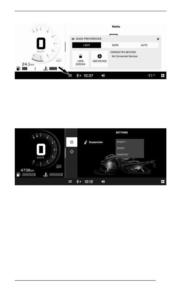
Quick Preferences
To access the Quick Preferences menu, press the following icon.
154
GAUGE - 10.25” COLOR TOUCHSCREEN DISPLAY
The Quick Preferences menu is to:
- Adjust the display appearance (Light/Dark/Auto)
- Lock the screen (press and hold anywhere on the screen to
unlock)
- Add a Bluetooth device
- View connected Bluetooth devices
Vehicle Settings
The Vehicle Settings applet is to:
- View vehicle Health:
- Vehicle information
- Faults (codes and description)
- Procedures (summerization)
- Adjust Smart-Shox suspension settings (if equipped)
155
GAUGE - 10.25” COLOR TOUCHSCREEN DISPLAY
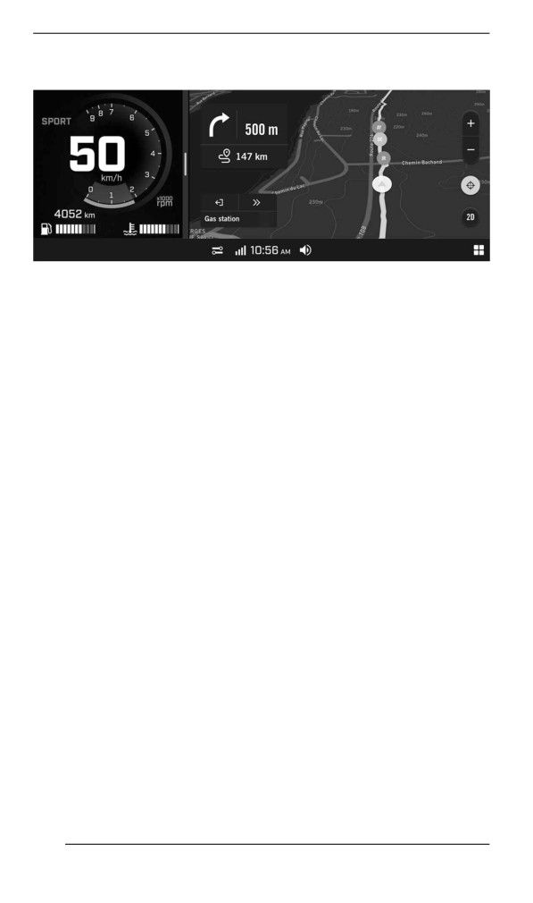
With the BRP GO! App
To use the Navigation applet on the display, you must connect (USB
connection) a mobile device with the BRP GO! app. The app can be
downloaded from the Apple App Store or Google Play Store via a sim-
ple search.
NOTE: For more information on the BRP GO! app, see the BRP GO!
section in this manual or visit the Ski-Doo website.
NOTE:
The smartphone must be connected with a USB cable to the USB port
located in the glove box.
User's personal data will be deleted from the cluster when the phone
disconnected.
User agrees that personal data (contact list and call history) be trans-
ferred to the cluster when smartphone is connected.
Warning Lamps and Indicators
The following indicator lamps will alert you to a vehicle condition that
may become serious. Some lamps will illuminate when starting the ve-
hicle to make sure they work. If any lamps remain on after starting the
vehicle, refer to the respective system warning lamp for further
information.
NOTE:
Some warning indicators appear in the display of the multifunction
gauge and function the same as an indicator lamp but do not display
when starting the vehicle.
Telltale Lights
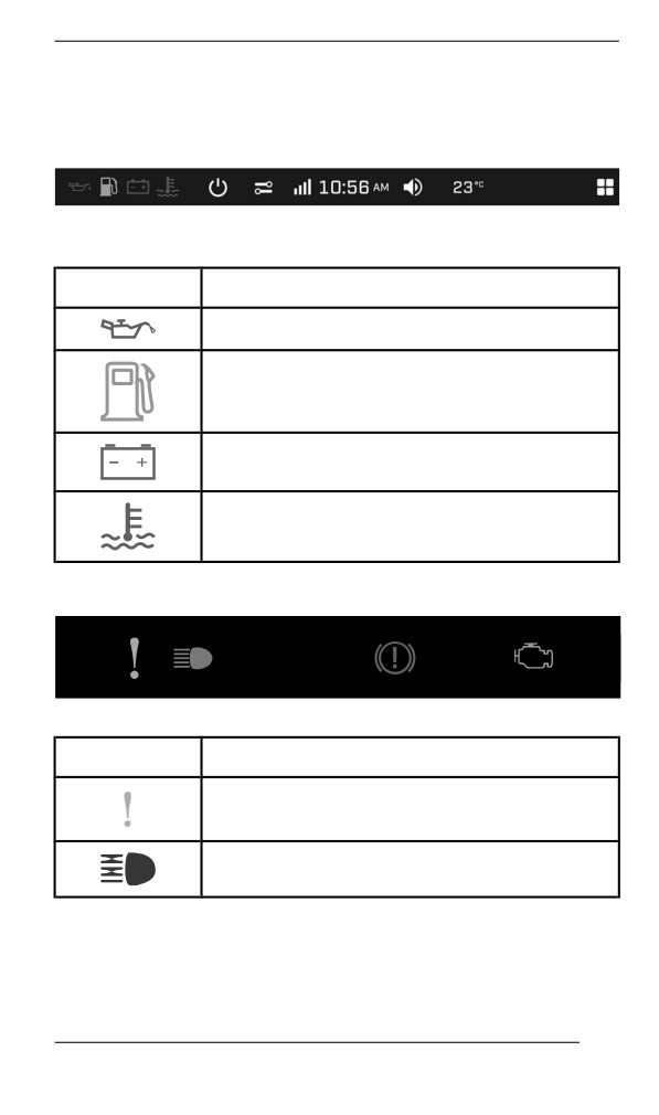
The telltale lights are separated on two levels:
156
GAUGE - 10.25” COLOR TOUCHSCREEN DISPLAY
- Digital bar
- Physical bar
Digital Bar
DIGITAL PILOT LAMP
–
10.25” COLOR DIGITAL
TOUCHSCREEN
Lights
Description
RED - Low engine oil pressure (if applicable)
ORANGE - Low fuel level
RED - The battery voltage too low or problem
with the electrical system
RED - The engine temperature is too high.
Physical Bar
PILOT LAMPS – 10.25” COLOR DIGITAL TOUCHSCREEN
Lights
Description
ORANGE - Vehicle malfunction
BLUE - The high beam are selected
157
GAUGE - 10.25” COLOR TOUCHSCREEN DISPLAY
Lights
Description
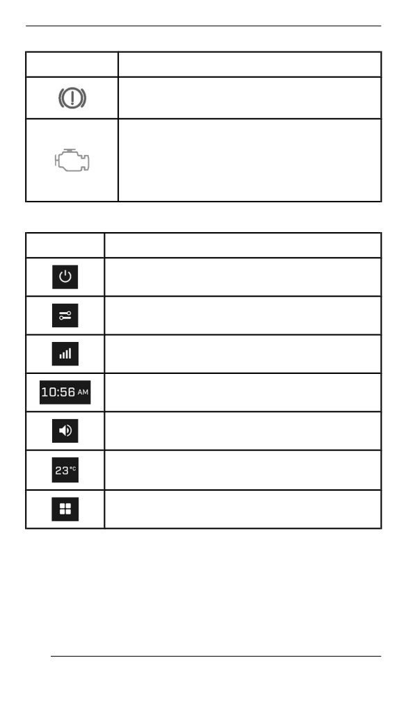
RED - Parking brake is engaged or malfunction
of the brake system
ORANGE
Turn on: Malfunction of the vehicle emissions
control system
Blink: Engine problems, the limp home mode is
activated. Have the vehicle serviced
immediately.
Icons and Indicators - Multifunction Display
Icon
Description
Shut down
Quick Preferences
Smartphone Network connection
Clock
Audio Volume
Ambient Temperature
Applet menu
Paiiring your Smartphone Via Blluetooth
On the Vehicle
1. Open the Applet menu.
2. Go to “Preferences”.
3. Select “Bluetooth”.
158
GAUGE - 10.25” COLOR TOUCHSCREEN DISPLAY
4. Select “Phone”.
5. Select “Add Device”.
NOTE: More than one smartphone can be paired with the vehicle.
However, only one will connect at any given time.
On the Phone
1. Activate your phone's bluetooth function.
Refer to your manufacturer's user guide for detailed procedure.
2. Select the bluetooth name of your vehicle display in the list of avail-
able devices.
3. A confirmation number will appear on the display and on the
phone. Make sure that the numbers match.
4. Press Pair on your phone.
5. Allow Contacts and Favorite Sync on your phone.
Pairing a Headset
To pair a headset, refer to Pairing your Smartphone Via Bluetooth and
select “Driver Headset” or “Passenger Headset”.
BRP GO! App
1) Download the BRP GO! Smartphone App
Download the BRP GO! app via the App Store for Apple™ or the Goo-
gle™ Play Store for Android.
2) Connect your smartphone using a USB cable
It is recommended to use an original charging cable from the smart-
phone OEM to optimize transfer between the phone and the vehicle.
Use the front USB port.
1. Unlock your phone screen
159
GAUGE - 10.25” COLOR TOUCHSCREEN DISPLAY
2. Connect your phone charging cable
3. A checkmark will appear on your phone screen once the connec-
tion is done.
3) Access the Navigation applet
In the Applet Menu, select "Navigation". You can also access the Navi-
gation applet if it is set in the Applet Switcher app rotation.
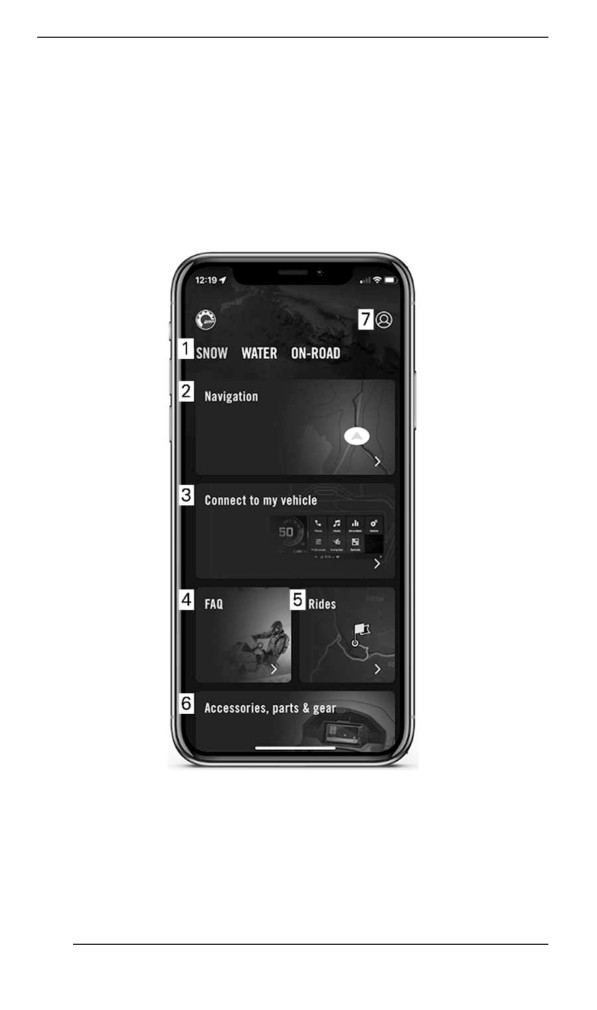
Quick Tour of the BRP GO! App
1. Playground: Select your playground to see content related to your
vehicle. For Ski-Doo snowmobiles, select the Snow playground.
2. Navigation: Access all the navigation features of the app such as
route planning, turn-by-turn navigation, friends location, offline nav-
igation, and more. You can access thousands of snowmobile trails
across North America and Europe on the map.
160
GAUGE - 10.25” COLOR TOUCHSCREEN DISPLAY
3. Connect to my vehicle: Easily access content on how to connect
the BRP GO! app to your vehicle display.
4. FAQ: This link takes you to answers of common questions asked
by riders like you. An internet connection is required.
5. Rides: Easily access your planned and completed rides made with
the Navigation features of the BRP GO! app.
6. Accessories, parts & gear : This link takes you to the online store
of your vehicle. An internet connection is required.
7. My Profile: Manage your profile and your account settings.
Messages iin Multifunction Gauge
Important information about vehicle condition is displayed on the multi-
function gauge. When starting the engine, always look at the gauge
for any indicator lamps or special messages.
Important information messages can also be displayed temporarily to
assist indicator lamps.
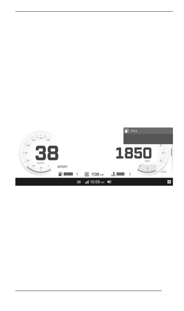
Notifications will always appear at the top right corner of the screen.
10.25” COLOR DIGITAL TOUCHSCREEN
There are two types of notifications:
- Vehicle notifications include warning, caution and notice messages
- Infotainment notifications include messages regarding connected
devices
Vehicle notifications have priority over infotainment notifications when
they are both present at the same time.
In the event vehicle goes into LIMP HOME, BRP recommends having
the vehicle transported. If you operate the vehicle in LIMP HOME,
avoid abrupt maneuvers and immediately go to the nearest authorized
BRP snowmobile dealer to have your vehicle serviced before riding
again. In LIMP HOME, the engine RPM is limited and therefore the ve-
hicle speed.
161
FUEL
Fuel Requirements
NOTICE
Always use fresh gasoline. Gasoline will oxidize; the result is
loss of octane, volatile compounds, and the production of gum
and varnish deposits which can damage the fuel system.
Alcohol fuel blending varies by country and region. Your vehicle has
been designed to operate using the recommended fuels, however, be
aware of the following:
- Use of fuel containing alcohol above the percentage specified by
government regulations is not recommended and can result in the
following problems in the fuel system components:
- Starting and operating difficulties.
- Deterioration of rubber or plastic parts.
- Corrosion of metal parts.
- Damage to internal engine parts.
- Inspect frequently for the presence of fuel leaks or other fuel sys-
tem abnormalities if you suspect the presence of alcohol in gaso-
line exceeds the current government regulations.
- Alcohol blended fuels attract and hold moisture which may lead to
fuel phase separation and can result in engine performance prob-
lems or engine damage.
Recommended Fuel
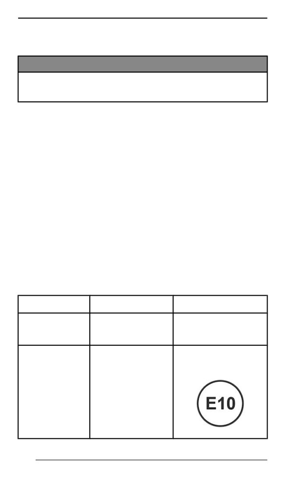
Use unleaded gasoline containing MAXIMUM 10% ethanol. The gaso-
line must have the following minimum octane requirements.
Fuel type
Engine
Min. octane rating
600R E-TEC
Fuel with NO
91 AKI (RON+MON)/2
850 E-TEC
ethanol
95 RON
850 E-TEC Turbo R
91 AKI (RON+MON)/2
95 RON
Fuel which may
600R E-TEC
contain up to
850 E-TEC
10% MAX
850 E-TEC Turbo R
ethanol
162
FUEL
NOTICE
Never experiment with other fuels. Engine or fuel system dam-
ages may occur with the use of an inadequate fuel.
NOTICE
Do NOT use fuel from fuel pumps labeled E85.
Use of fuel labeled E15 is prohibited by U.S. EPA Regulations.
Fueliing Procedure
WARNING
Always stop engine before refueling.
WARNING
Fuel is flammable and explosive under certain conditions.
Never use an open flame to check fuel level.
Never smoke or allow flame or spark in vicinity.
Always work in a well-ventilated area.
NOTE:
Do not sit or lean on seat when fuel tank cap is not properly installed.
1. Stop engine.
2. Have operator and passenger get off vehicle.
WARNING
Do not allow anyone seated on the vehicle while fueling.
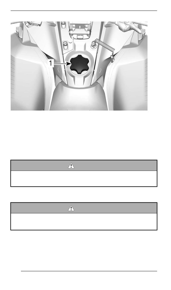
3. Unscrew slowly the fuel reservoir cap counterclockwise to stabilize
pressure before removing it.
NOTE:
A short whistling sound is normal.
163
FUEL
TYPICAL
1. Fuel tank cap
4. Insert the spout into the filler neck.
5. Pour fuel slowly so that air can escape from the tank and prevent
fuel flow back. Be careful not to spill fuel.
6. Stop filling when the fuel reaches the bottom of filler neck. Do not
overfill.
WARNING
Never top up the fuel tank before placing the vehicle in a warm
area. As temperature increases, fuel expands and may
overflow.
7. Fully tighten fuel reservoir cap clockwise.
WARNING
Always wipe off any small fuel spillage from the vehicle. If a ma-
jor spillage occurs, remove side panels to remove fuel vapors
from engine compartment before starting.
NOTE:
Do not sit or lean on seat when fuel tank cap is not properly installed.
164
INJECTION OIL
Recommended Injectiion Oiil
Rotax® engines were developed and validated using the XPS® oil.
BRP recommends the use of its XPS injection oil or an equivalent at
all time. Damages caused by the use of an injection oil not suitable for
this 2-stroke direct fuel injection engine may not be covered by the
BRP Limited Warranty.
RECOMMENDED Injection Oil
600 EFI
XPS 2T Synthetic Blend Oil (semi-synthetic)
600R E-TEC
XPS 2T E-TEC Synthetic Oil (full synthetic)
850 E-TEC
IF THE RECOMMENDED XPS ENGINE OIL IS NOT
AVAILABLE
Use a 2-stroke lubricant designed for snowmobiles meeting or
exceeding the following lubricant industry specifications:
- JASO FD (M345-2004)
- SAE Grade 4 (F / M 4)
Injjection Oill Levell Verification
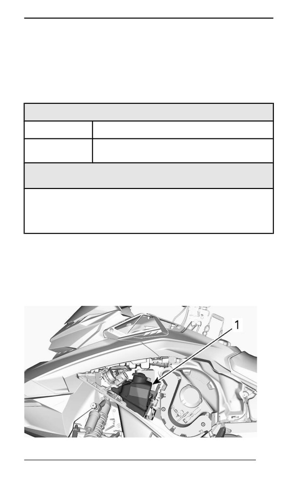
The injection oil reservoir is located behind the LH side panel. Refer to
Equipment for opening procedure.
Always maintain a sufficient amount of recommended injection oil in
the injection oil reservoir.
1. Oil reservoir
165
INJECTION OIL
Marks on the tank indicates "3/8" and "1/2" of the total amount of oil.
NOTICE
Check level and refill every time you refuel.
Adding Injection Oil
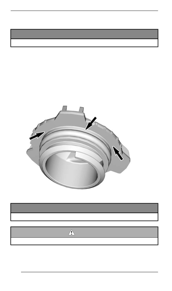
Remove injection oil reservoir cap.
Add injection oil.
NOTE:
Do not overfill.
Wipe the reservoir cap seal and flange area.
Reinstall cap.
NOTICE
Do not overtighten.
WARNING
Wipe off any oil spills. Oil is highly flammable when heated.
166
BREAK-IN PERIOD
Operation Duriing Break-In
Engine
During the break-in period:
- Avoid prolonged full throttle operation.
- Avoid sustained accelerations.
- Avoid prolonged cruising speeds.
- Avoid engine overheating.
However, brief accelerations and speed variations contribute to a
good break-in.
During a predetermined period, the engine management system con-
trols some engine parameters.
The duration is based on fuel volume. It will take approximately two
fuel tanks to complete the break-in.
During this period:
- The engine performance and behavior will not be optimal.
- The fuel and oil consumption will be higher.
Drive Belt
A new drive belt requires a break in period of 50 km (30 mi).
During the break-in period:
- Avoid strong acceleration and deceleration.
- Avoid pulling a load.
- Avoid high speed cruising.
If the vehicle creeps, lower the drive belt height from the preliminary
setting. Refer to Drive Belt in maintenance procedure.
167
BASIC PROCEDURES
Engiine Starting Procedure
Procedure
1. Apply parking brake.
2. Recheck throttle control lever operation.
3. Put your helmet on.
4. Ensure that the tether cord cap is installed on the engine cut-off
switch and that the cord is attached to your clothing eyelet.
5. Ensure that the emergency engine stop switch is in the ON position
(up).
WARNING
Never depress throttle while starting engine.
6. Release parking brake.
NOTE:
For an initial cold start, do not release parking brake. Perform the ve-
hicle warm-up procedure as explained below.
Manual Start Modells
Grab rewind starter handle, pull handle slowly until a resistance is felt,
then hold handle firmly and pull vigorously to start engine.
NOTE:
The maximum torque that can be transmitted to the engine by the re-
wind starter is 80 Nm (59 lbf-ft). The maximum force that can be ex-
erted on the on the rope is 2 200 N (494.6 lbf).
Electriic Start Models
Press the START/RER button to engage the electric starter and start
the engine. Release button immediately when engine has started.
NOTICE
Do not engage electric starter for more than 10 seconds at a
time. A rest period should be observed between the cranking
cycles to allow electric starter to cool down.
Emergency Starting
The engine can be started with the emergency starter rope supplied in
the storage compartment. Refer to Body and Seat.
168
BASIC PROCEDURES
Remove the drive belt guard. Refer to Body and Seat.
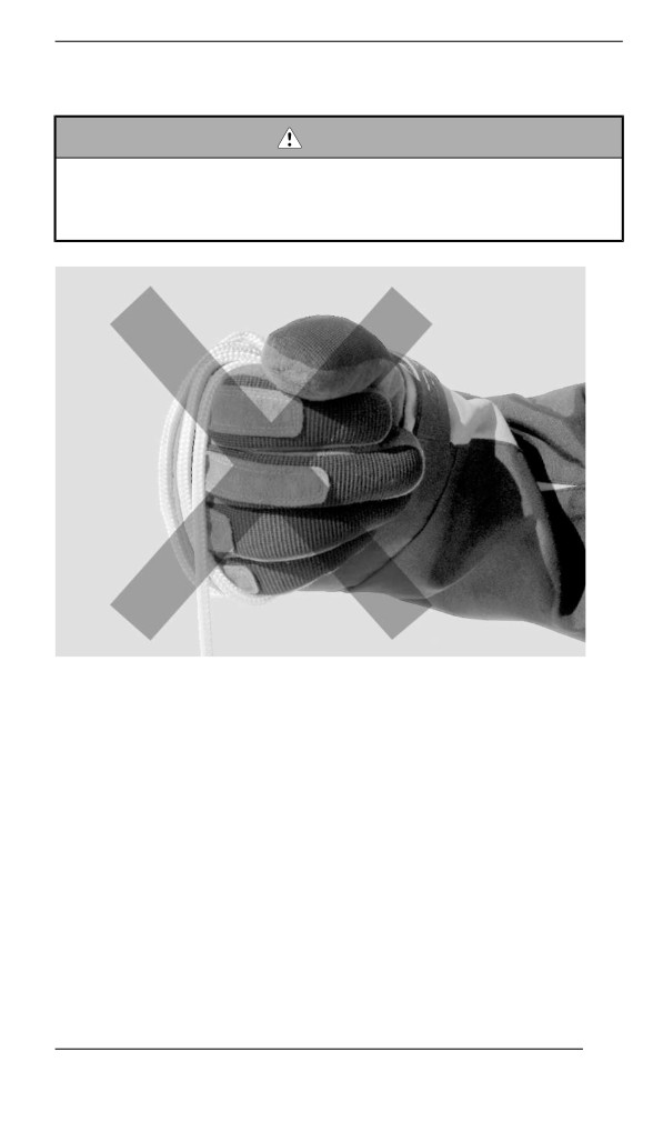
WARNING
Do not wind starting rope around your hand. Hold rope by the
handle only. Do not start the engine by the drive pulley unless it
is a true emergency situation. Have the snowmobile repaired
as soon as possible.
Attach one end of emergency rope to the rewind handle.
NOTE:
The suspension adjustment tool can be used as an emergency
handle.
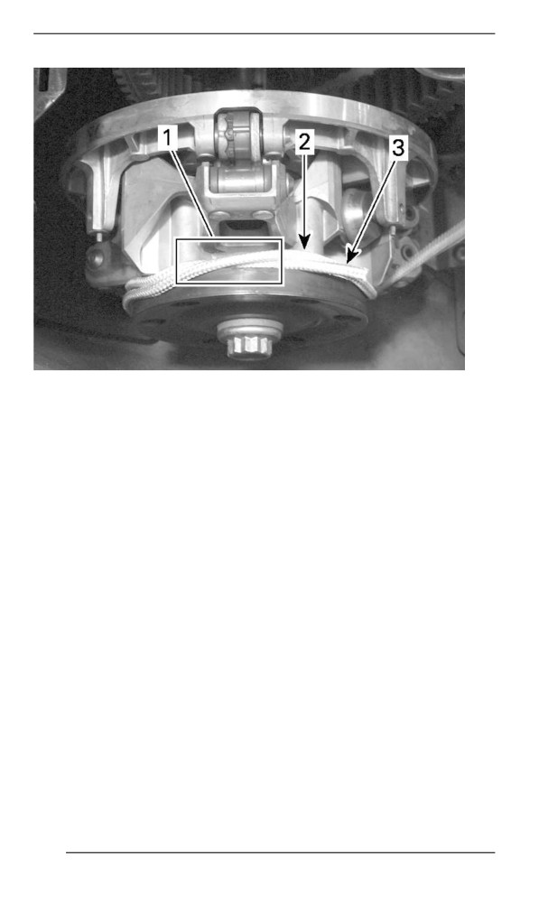
Cross the rope on the first turn as shown.
169
BASIC PROCEDURES
1. Rope crossed
2. Rope to be winded
3. Rope end
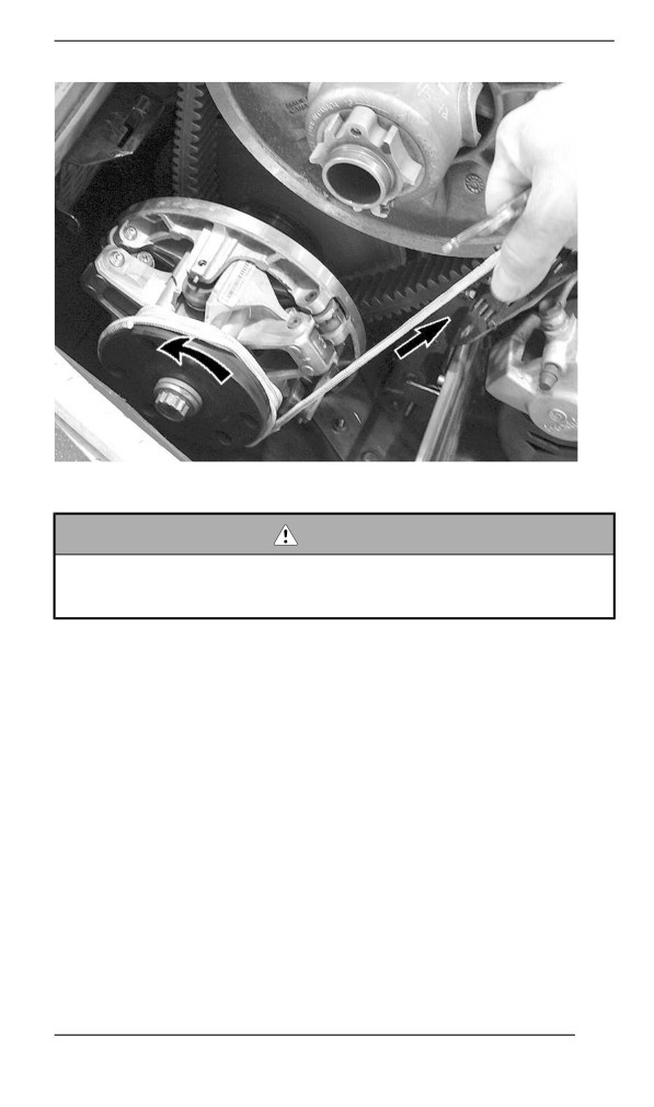
Wind rope two turns counterclockwise tightly around the drive pulley
where shown.
Pull the rope using a sharp, crisp pull so the rope comes free of the
drive pulley.
170
BASIC PROCEDURES
Start engine as per usual manual starting.
WARNING
When starting the snowmobile in an emergency situation, using
drive pulley, do not reinstall the belt guard and return slowly to
have snowmobile repaired.
Vehicle Warm-Up
Before every ride, vehicle has to be warmed up as follows.
1. Start engine as explained in Engine Starting Procedure above.
2. Allow engine to warm up one or two minutes at idle speed.
NOTE:
Engine will shut down after approximately 12 minutes of idling.
3. Disengage parking brake.
4. Apply throttle until drive pulley engages. Drive at low speed the first
two or three minutes.
171
BASIC PROCEDURES
NOTICE
If vehicle does not move when throttle is applied, stop engine,
remove tether cord cap from the engine cut-off switch, then do
the following.
– Check if skis are stuck on the ground. Lift one ski at a time
by the handle, then put it down.
– Check if track is stuck on the ground. Lift rear of snowmobile
enough to clear track from the ground, then drop.
– Check rear suspension for hard snow or ice accumulation
that could interfere with track rotation. Clean the area.
CAUTION
Beware of injuries by using proper lifting techniques, notably
using your legs force. Do not attempt to lift the rear of vehicle if
it is above your limits.
WARNING
Make sure tether cord cap is removed before standing in front
the vehicle, getting close to the track or rear suspension
components.
NOTE:
Warm-up is electronically controlled. During this period (up to 10 mi-
nutes depending on ambient temperature), engine RPM is limited.
Reverse (RER)
When the engine is running, depressing the RER button will slow
down engine RPM to almost a stop and advance the ignition timing to
invert crankshaft rotation.
- Engine will automatically shift into forward when restarting after
stopping or stalling.
- Shifting procedure will take place only when the engine is running.
- If engine is running at a speed above 4300 RPM, the function of
the RER button is disabled.
- It is recommended to warm up the engine to its normal operating
temperature before shifting.
Shifting in Reverse
1. Bring vehicle to a complete stop.
2. Apply and hold brake. Remain seated, refer to Rider Position (Re-
verse Operation) in Riding the vehicle for posture information.
172
BASIC PROCEDURES
3. With engine at idle speed, select reverse (R) gear using the Start /
RER button.
4. Wait until reverse beeper sounds, then gently depress throttle
lever.
WARNING
The reverse speed is not limited. Always proceed with caution
as fast reverse could result in loss of vehicle stability. Come to
complete stop before activating the reverse. Always remain
seated and apply the brake before shifting. Ensure the path be-
hind is clear of obstacles or bystanders before proceeding.
Shifting in Forward from Reverse
1. Bring vehicle to a complete stop.
2. Apply and hold brake.
3. Press and release the RER button.
4. Apply throttle slowly and evenly. Allow drive pulley to engage then
accelerate carefully.
Shuttiing Off the Engine
Release throttle lever and wait until engine has returned to idle speed.
Shut off the engine using either the emergency engine stop switch or
by pulling off the tether cord cap from the engine cut-off switch.
WARNING
Always remove the tether cord cap from engine cut-off switch
when vehicle is not in operation in order to prevent accidental
engine starting or to avoid unauthorized use by children or
others or theft.
173
RIDING CONDITIONS AND YOUR
SNOWMOBILE
Altitude
At factory, your snowmobile was calibrated to be used within an alti-
tude range (relative to sea level).
A new snowmobile has a tag attached to the handlebar indicating its
calibration. Refer to Safety Information on Vehicle.
If for any reason you don't know your snowmobile calibration, contact
an authorized BRP snowmobile dealer.
If your snowmobile is to be used at an altitude outside the specified
range, have it calibrated accordingly by an authorized BRP snowmo-
bile dealer.
NOTICE
An inappropriate altitude calibration would decrease perform-
ance and may cause serious damage to the snowmobile.
Temperature
The engine management of these engines provides the optimum air/
fuel ratio for all temperatures.
Hard Packed Snow
All models covered in this guide which are equipped with a minimum
track profile of 44 mm (1.75 in) are built for deep snow conditions and
should never be used during a prolonged period of time in marginal or
hard packed snow conditions.
In the event you have to ride in these types of conditions:
- Avoid exceeding a speed of 70 km/h (45 mph) in all conditions
- Avoid hard acceleration (over 75% of throttle)
- Ice scratchers should be applied
- Engine temperature should not exceed 75% on the temperature
gauge.
NOTICE
Running these types of tracks at high speed on a trail, on hard
packed surfaces or on ice puts more stress on the lugs, which
tends to heat up as a result. It also could drastically reduce the
life of specific wear parts. To avoid potential degradation, de-
lamination or damages to the track and wear parts, reduce your
speed and minimize the distance that is being ridden on these
types of surfaces.
174
RIDING CONDITIONS AND YOUR SNOWMOBILE
Vehicles Equipped with Ice Scratchers
Ice scratchers are equipped on the vehicle to increase engine cooling
efficiency, to lubricate and to cool track clips and sliders. They must
be used whenever on ice, hard packed snow, or any conditions that
do not lift enough snow particles into the rear suspension and the
tunnel.
NOTICE
Although it is not recommended to ride a snowmobile equipped
with a high lug profile track on trails or hard packed snow condi-
tions, it is highly suggested to combine idler wheels and ice
scratchers on a vehicle used in these conditions.
IMPORTANT
Ridding in these trail conditions puts the reliability of the track and
its warranty at risk
If equipped with the following track profile heights, never exceed the
recommended sustained vehicle speeds listed.
Track Profile Height
Maximum Sustained Speed
57 mm (2.25 in)
110 km/h (70 MPH)
60 mm (2.36 in)
64 mm (2.52 in)
95 km/h (60 MPH)
75 mm (3 in)
175
TUNE YOUR RIDE
Snowmobile handling and comfort depend upon multiple adjustments.
WARNING
Suspension adjustment could affect vehicle handling. Always
take time to familiarize yourself with the vehicle''s behavior after
any suspension adjustment have been made. Always adjust LH
and RH suspension components to the same setting.
Choice of suspension adjustments vary with carrying load, operator's
weight, personal preference, riding speed and field condition.
NOTE:
Some adjustments may not apply to your snowmobile.
WARNING
Before proceeding with any suspension adjustment, remember:
– Park in a safe place.
– Remove the tether cord cap from the engine cut-off switch.
– Use appropriate lifting device or have assistance to share
lifting stress. If a lifting device is not used, use proper lifting
techniques, notably using your legs force.
– Do not attempt to lift the front or rear of vehicle if it is above
your limits.
– Support front of vehicle off the ground with a suitable device
before adjusting suspension.
– Support rear of vehicle off the ground with a wide-base
snowmobile stand with a rear deflector panel.
– Make sure support device is stable and secure.
The best way to set up the suspension is to customize each adjust-
ment one at a time. Various adjustments are interrelated. It may be
necessary to readjust center spring after adjusting front springs for in-
stance. Test run the snowmobile under the same conditions; trail,
speed, snow, operator riding position, etc. Proceed methodically until
you are satisfied.
Following are guidelines to fine-tune suspension. Use suspension ad-
justment tool provided in the tool kit.
Front Suspension Adjustments
Ski Stance
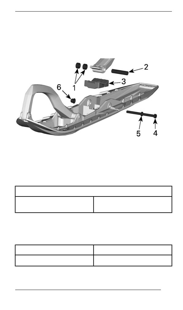
Skis can be set to three different widths.
To obtain the different widths, place the spacers:
176
TUNE YOUR RIDE
- Inside the skis leg (narrowest ski stance setting: easiest to initiate
turn on sidehills), or
- Outside the skis leg (widest ski stance setting: most stable on cor-
ners), or
- On each side (central setting: best steering accuracy on deep
snow).
1. Spacers
2. Axle
3. Stopper
4. Screw
5. Washer
6. Nut
TIGHTENING TORQUE
48 ± 6 Nm
Ski nut
(35 ± 4 lbf-ft)
Front Springs
Front spring preload has an effect on front suspension firmness.
Front spring preload also has an effect on the steering behavior.
Action
Result
Increasing preload
Firmer front suspension
177
TUNE YOUR RIDE
Action
Result
Higher front end
More precise steering
More bump absorption
capability
Softer front suspension
Lower front end
Decreasing preload
Lighter steering
Less bump absorption
capability
WARNING
Adjust both springs to the same preload. Uneven adjustment
can cause poor handling and loss of stability, and/or control,
and increase the risk of an accident.
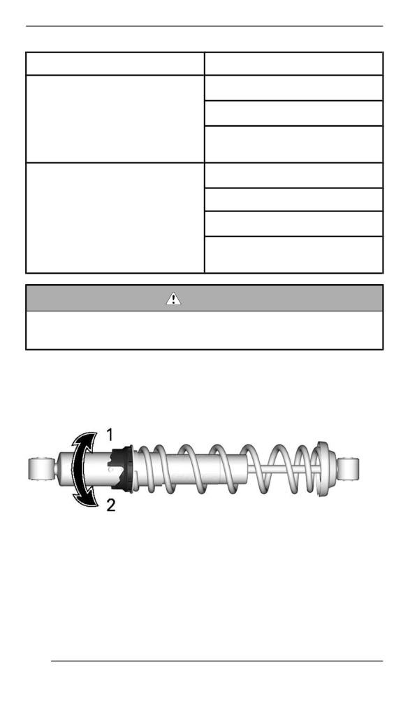
Cam Type Adjuster
Using the suspension adjustment tool provided in the tool kit, turn the
cam to increase or decrease the spring preload.
1. Increase preload
2. Decrease preload
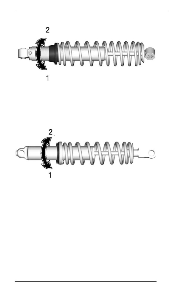
Ring Adjuster – Type 1
Grab and turn the ring and the spring to increase or decrease the
spring preload.
178
TUNE YOUR RIDE
1. Increase preload
2. Decrease preload
Ring Adjuster – Type 2
Grab and turn the ring and the spring to increase or decrease the
spring preload.
1. Increase preload
2. Decrease preload
Front Shock Absorber Adjustments (KYB HLCR Series Only)
Compressiion Damping
Low speed compression damping controls how the shock absorber re-
acts to a low suspension velocity (slow compression strokes, in most
cases when riding at lower speeds).
High speed compression damping controls how the shock absorber
reacts to a high suspension velocity (quick compression strokes, in
most cases when riding at higher speeds).
179
TUNE YOUR RIDE
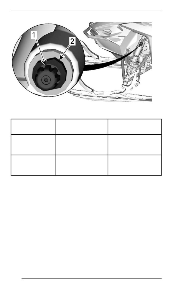
1. Low speed compression adjuster (button)
2. High speed compression adjuster
Result on big and
Turning
Action
small bumps
Increasing
Firmer compression
Clockwise
compression
damping
damping force
Decreasing
Counter
Softer compression
compression
Clockwise
damping
damping force
Rebound Dampiing
Rebound damping controls how the shock absorber restrains the ex-
tension stroke.
180
TUNE YOUR RIDE
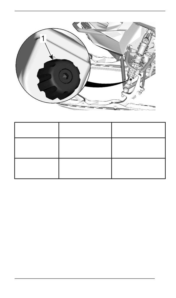
1. Rebound adjuster
Result on big and
Turning
Action
small bumps
Firmer rebound
Increasing rebound
Clockwise
damping (slower
damping force
extension speed)
Softer rebound
Counter
Decreasing rebound
damping (faster
Clockwise
damping force
extension speed)
NOTE:
In repetitive short small bumps (ripple), it is recommended to use a
lower rebound damping setting.
181
TUNE YOUR RIDE
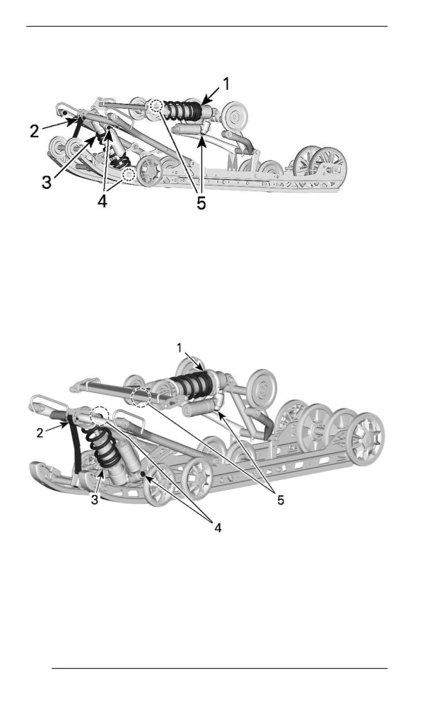
Rear Suspensiion Adjustments
PPS2 - ADJUSTABLE COMPONENTS
1. Rear spring
2. Stopper strap
3. Center spring
4. Center shock absorber
5. Rear shock absorber
PPS3 - ADUSTABLE COMPONENTS
1. Rear spring
2. Stopper strap
3. Center spring
4. Center shock absorber
5. Rear shock absorber
182
TUNE YOUR RIDE
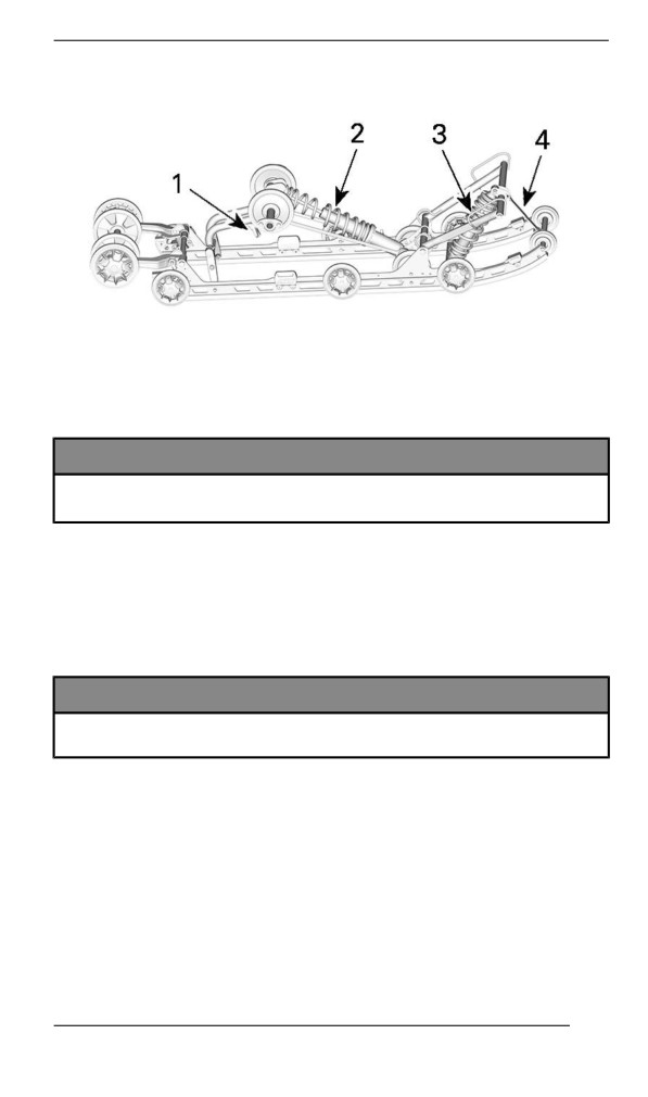
EASYRIDE - ADJUSTABLE COMPONENTS
1. Easy Adjust Handle (if equipped)
2. Rear spring
3. Center spring
4. Stopper strap
NOTICE
Whenever adjusting rear suspension, check track tension and
adjust if necessary.
Stopper Strap – PPS Suspension
Stopper strap length has an effect on the amount of weight the center
spring has to carry especially during acceleration, therefore on the
front end uplift.
Stopper strap length also has an effect on center spring travel.
NOTICE
Whenever stopper strap length is changed, track tension must
be checked.
NOTE:
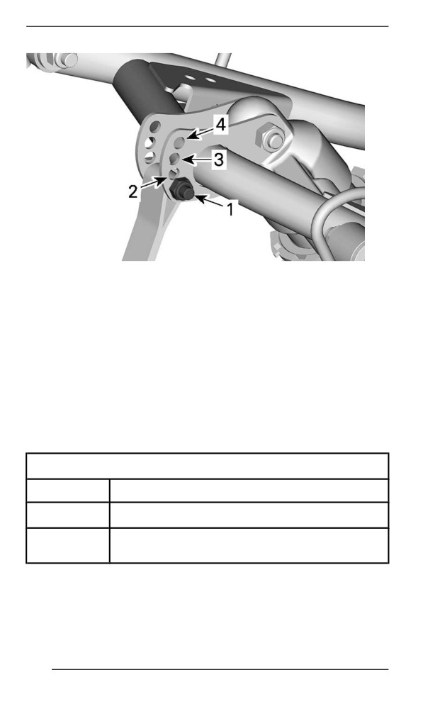
Stopper strap can be set to position 1, 2, 3 or 4. Smaller numbers cor-
respond to a longer strap setting.
183
TUNE YOUR RIDE
STOPPER STRAP POSITIONS
1. Position 1 (longest)
2. Position 2
3. Position 3
4. Position 4 (shortest)
When operating the snowmobile in deep snow or hill climbing, it may
be necessary to vary stopper strap length and/or riding position, to
change the angle at which the track rides on the snow. Operator's fa-
miliarity with the various adjustments as well as snow conditions will
dictate the most efficient combination.
Generally, a longer stopper strap setting gives better performance on
a flat landscape and a shorter setting will improve handling in steep hill
climbing and deep snow conditions.
Stopper Strap Setting
Position
Use
1
Standard setting: Best overall setting for trail usage
Better performance in cornering, less suspension
2
travel
184
TUNE YOUR RIDE
Stopper Strap Setting
Position
Use
Hill climb:
- Better track attack angle for hill climbing
3
- Better maneuverability on deep snow and on
sidehilling
Steep hill climb:
- Better track attack angle for hill climbing
4
- Less transfer
- Lower ride height
Stopper Strap – EasyRide Suspension
Stopper strap length has an effect on the amount of weight the center
spring has to carry especially during acceleration, therefore on the
front end uplift.
Stopper strap length also has an effect on center spring travel.
NOTICE
Whenever stopper strap length is changed, track tension must
be checked.
NOTE:
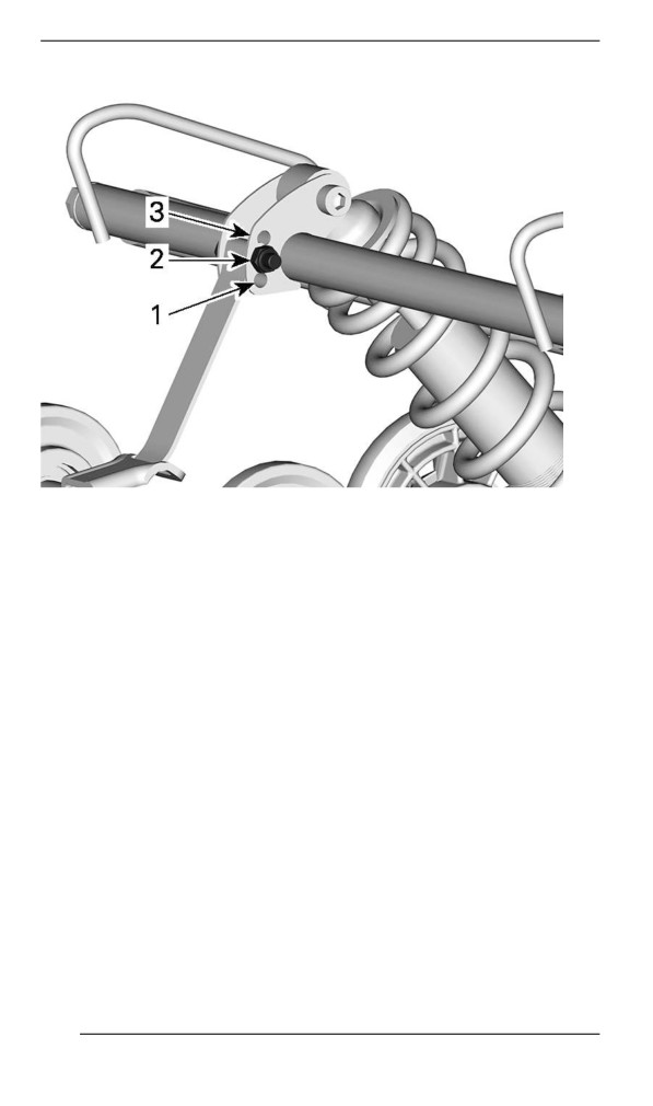
Stopper strap can be set to position 1, 2 or 3. Smaller numbers corre-
spond to a longer strap setting.
185
TUNE YOUR RIDE
STOPPER STRAP POSITIONS
1. Position 1 (longest)
2. Position 2
3. Position 3 (shortest)
When operating the snowmobile in deep snow or hill climbing, it may
be necessary to vary stopper strap length and/or riding position, to
change the angle at which the track rides on the snow. Operator's fa-
miliarity with the various adjustments as well as snow conditions will
dictate the most efficient combination.
Generally, a longer stopper strap setting gives better performance on
a flat landscape and a shorter setting will improve handling in steep hill
climbing and deep snow conditions.
186
TUNE YOUR RIDE
Stopper Strap Setting
Position
Use
Boon docking:
1
- Better bump absorption
- Lighter and easier handling on flat landscape.
2
Standard setting: Best overall setting (general use)
Hill climb:
- Better track attack angle for hill climbing
3
- Less transfer
- Lower ride height
Center Spring
Center spring preload has an effect on steering effort, handling and
bump absorption.
Also, since center spring preload adjustment puts more or less pres-
sure on the front of the track, it has an effect on the performance in
deep snow.
Action
Result
Lighter steering
More bump absorption
capability
Increasing preload
Better deep snow starts
Better deep snow performance
and handling
Heavier steering
Less bump absorption
Decreasing preload
capability
Better trail handling
Cam Type Adjuster
187
TUNE YOUR RIDE
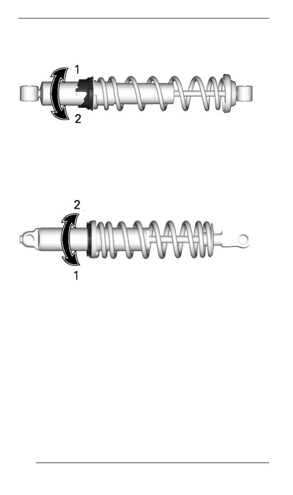
Using the suspension adjustment tool provided in the tool kit, turn the
cam to increase or decrease the spring preload.
1. Increase preload
2. Decrease preload
Ring Type Adjuster
Grab and turn the ring and the spring to increase or decrease the
spring preload.
1. Increase preload
2. Decrease preload
Rear Spring – PPS3
Rear spring preload has an effect on comfort, ride height and load
compensation.
Also, adjusting rear spring preload shifts more or less weight to the
snowmobile front end. As a result, more or less weight is applied to
the skis. This has an effect on performance in deep snow, steering ef-
fort and handling.
Slight suspension bottoming occurring under the worst riding condi-
tions indicates a good choice of spring preload.
188
TUNE YOUR RIDE
Action
Result
Firmer rear suspension
Higher rear end
Increasing preload
More bump absorption capability
Heavier steering
Softer rear suspension
Lower rear end
Less bump absorption capability
Decreasing preload
Lighter steering
Better deep snow performance and
handling
Refer to the following to determine if preload is correct.
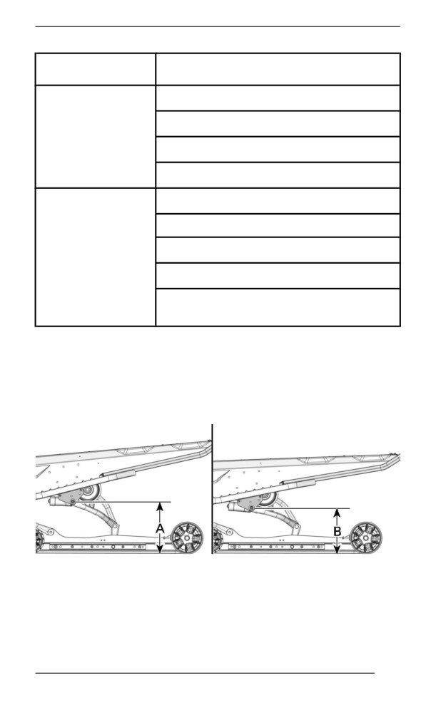
- A = Suspension fully extended (For fully extended the suspension,
lifted the rear bumper before taking the measurement.)
- B = Suspension has collapsed with operator, passenger(s) and
load added
- C = Distance between dimension “A” and “B”, see table below
TYPICAL - DISTANCE BETWEEN GROUND AND UPPER REAR
ARM PIVOT
189
TUNE YOUR RIDE
C
What to do
90 to 100 mm (3.6 to 4 in)
No adjustment required
More than
Adjusted too soft. Increase
100 mm (4 in)
preload
Less than
Adjusted too firm. Decrease
90 mm (3.6 in)
preload
NOTE:
If the specification is unattainable with the original springs, visit an au-
thorized BRP snowmobile dealer for other available springs.
For normal setting, refer to Suspension Adjustment Table.
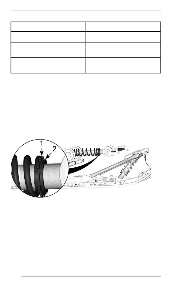
To adjust, unscrew the locking ring, then turn the adjustment ring to
set the spring preload.
When the desired preload is set, tighten the locking ring against the
adjustment ring.
1. Adjustment ring
2. Locking ring
Center and Rear Shock Absorber Adjustments (KYB HCLR
Series Only)
Compression Dampiing
Low speed compression damping controls how the shock absorber re-
acts to a low suspension velocity (slow compression strokes, in most
cases when riding at lower speeds).
190
TUNE YOUR RIDE
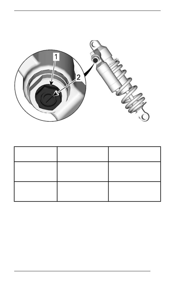
High speed compression damping controls how the shock absorber
reacts to a high suspension velocity (quick compression strokes, in
most cases when riding at higher speeds).
1. High speed compression adjuster (hexagonal)
2. Low speed compression adjuster (slotted)
Result on big and
Turning
Action
small bumps
Increasing
Firmer compression
Clockwise
compression
damping
damping force
Decreasing
Counter
Softer compression
compression
Clockwise
damping
damping force
Rebound Damping
Rebound damping controls how the shock absorber restrains the ex-
tension stroke.
191
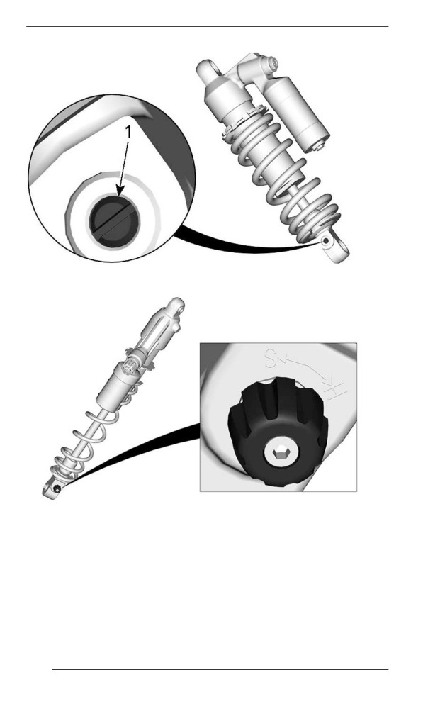
TUNE YOUR RIDE
1. Rebound adjuster
192
TUNE YOUR RIDE
Result on big and
Turning
Action
small bumps
Firmer rebound
Increasing rebound
Clockwise
damping (slower
damping force
extension speed)
Softer rebound
Counter
Decreasing rebound
damping (faster
Clockwise
damping force
extension speed)
NOTE:
In repetitive short small bumps (ripple), it is recommended to use a
lower rebound damping setting.
Adjustment Tiips According to Vehiiclle Behaviior
Problem
Corrective measures
Check ski alignment.
-
Reduce front suspension spring
Front suspension darting
preload.
-
Increase center spring preload.
–
Reduce rear spring preload.
-
Reduce front suspension spring
Steering feels too heavy
preload.
at steady speeds
-
Increase center spring preload.
Steering feels too heavy
-
Reduce rear spring preload.
during acceleration
–
Lengthen limiter strap.
Too much ski lift during
-
Shorten limiter strap.
cornering or acceleration
–
Increase rear spring preload.
-
Reduce rear spring preload.
Rear of snowmobile
–
Reduce compression damping
seems too stiff
adjustment
if equipped
Rear of snowmobile
-
Increase rear spring preload.
seems too soft
193
TUNE YOUR RIDE
Problem
Corrective measures
- Increase compression damping
adjustment
Rear suspension is
if equipped.
frequently bottoming
- Increase rear spring preload.
- Increase center spring preload.
- Lengthen limiter strap.
- Reduce center spring preload.
- Increase rear spring preload.
Snowmobile seems to
- Increase front suspension spring
pivot around its center
preload.
- Shorten limiter strap.
- Reduce rear spring preload.
Track spins too much at
- Increase center spring preload.
start
- Lengthen limiter strap.
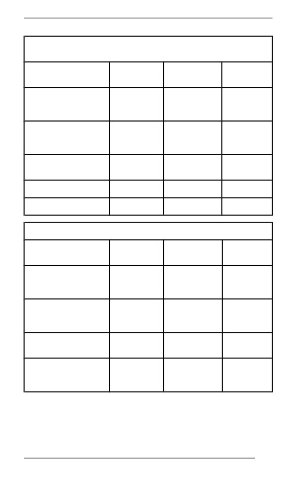
Suspensiion Adjjustment Tablle
NOTE:
Clicks and turns counted from closed position.
Front Spring / Shock absorber settings
Normal
Setting
Comfort
Sport
(Standard)
Low speed
compression
45
40
24
(Clicks)
High speed
compression
2.5
2
1.5
(Turns)
Rebound
26
24
22
(Clicks)
Spring preload (mm)
8
8
8
194
TUNE YOUR RIDE
Center Spring / Shock absorber
Stopper strap settings
Normal
Setting
Comfort
Sport
(Standard)
Low speed
compression
45
40
28
(Clicks)
High speed
compression
2.5
2
1.5
(Turns)
Rebound
12
11
8
(Clicks)
Spring preload (mm)
3
3
1
Limiter strap position
#1
#2
#2
Rear Spring / Shock absorber settings
Normal
Setting
Comfort
Sport
(Standard)
Low speed
compression
45
40
28
(Clicks)
High speed
compression
2.5
2
1.5
(Turns)
Rebound
12
11
8
(Clicks)
Spring preload (mm)
(With stopper strap
12
12
12
removed)
NOTE:
For E-Start and/or Link-Q equipped models, add 1 full turn preload
(1,5 mm) on rear shock.
195
TUNE YOUR RIDE
This page is intention-
ally blank
196
MAINTENANCE
197
MAINTENANCE SCHEDULE
Maintenance is very important to keep your vehicle in safe operating
condition. The vehicle should be serviced as per the maintenance
schedule.
Proper maintenance is the owner’s responsibility. A warranty claim
may be denied if, among other things, the owner or operator caused
the problem through improper maintenance or use.
Perform periodic checks and follow the maintenance schedule. The
maintenance schedule does not exempt the pre-ride inspection.
WARNING
Failure to properly maintain the vehicle according to the main-
tenance schedule and procedures can make it unsafe to
operate.
EPA Regullatiion - Canadiian and USA Vehiiclles
A repair shop or person of the owner''s choosing may maintain,
replace, or repair emission control devices and systems. These in-
structions do not require components or service by BRP or authorized
BRP snowmobile dealers.
Although an authorized BRP snowmobile dealer has an in-depth tech-
nical knowledge and tools to service your vehicle, the emission-related
warranty is not conditioned on the use of an authorized BRP snowmo-
bile dealer or any other establishment with which BRP has a commer-
cial relationship.
Proper maintenance is the owner’s responsibility. A warranty claim
may be denied if, among other things, the owner or operator caused
the problem through improper maintenance or use.
For emission-related warranty claims, BRP is limiting the diagnosis
and repair of emission-related parts to the authorized BRP snowmo-
bile dealers. For more information, please refer to the US EPA Emis-
sions PERFORMANCE WARRANTY contained in the warranty
section.
You must follow the instructions for fuel requirements in the fueling
section of this manual. Even if gasoline containing greater than ten
volume percent ethanol is readily available, the US EPA issued a pro-
hibition against the use of gasoline containing greater than 10 vol %
ethanol that applies to this vehicle. The use of gasoline containing
greater than 10 vol% ethanol with this engine may harm the emission
control system.
198
MAINTENANCE SCHEDULE
Deep Snow/ Traiil/ Crossover/ Utiiliity Usage
Whether your vehicle is a Deep Snow, Trail, Crossover, or Utility mod-
el, these types of usage require maintenance tasks to be performed
between the regular yearly intervals. These are identified as A+ in the
chart below.
If you regularly ride deep snow and perform frequent hill climbs,
follow the A+ Deep Snow interval and perform the tasks outlined in the
chart below.
If you regularly ride in trails, explore the countryside, or work with
your snowmobile, follow the A+ Trail / Crossover / Utility interval and
perform the tasks outlined in the chart below.
199
MAINTENANCE SCHEDULE
Maiintenance Schedulle
Make sure to perform proper maintenance at recommended intervals
as indicated in the tables.
The maintenance chart indicates the items needing to be addressed
based on 2 criteria, whichever happens first:
- Calendar time
- Odometer reading.
Your driving habits determines the factors you shall adhere too. For
example:
- Someone who uses their vehicle every weekend trail riding would
most likely follow the odometer reading to determine the fre-
quency of his maintenance.
- Someone who uses their vehicle seldomly over the year or only on
a few occasions would follow the calendar time to determine the
frequency of his maintenance.
IMPORTANT: The following tables show the appropriate mainte-
nance application for the first 2 years. For subsequent years, repeat
the same pattern alternatively.
Maiintenance Overviiew
Calendar
Trail/ Cross
Odometer
Time
Over/ Utility
Every
1500 km (1000 mi)
A+
Month
1 Year
3000 km (2000 mi)
A
Every
4500 km (3000 mi)
A+
Month
2 Years
6000 km (4000 mi)
A and B
200
MAINTENANCE SCHEDULE
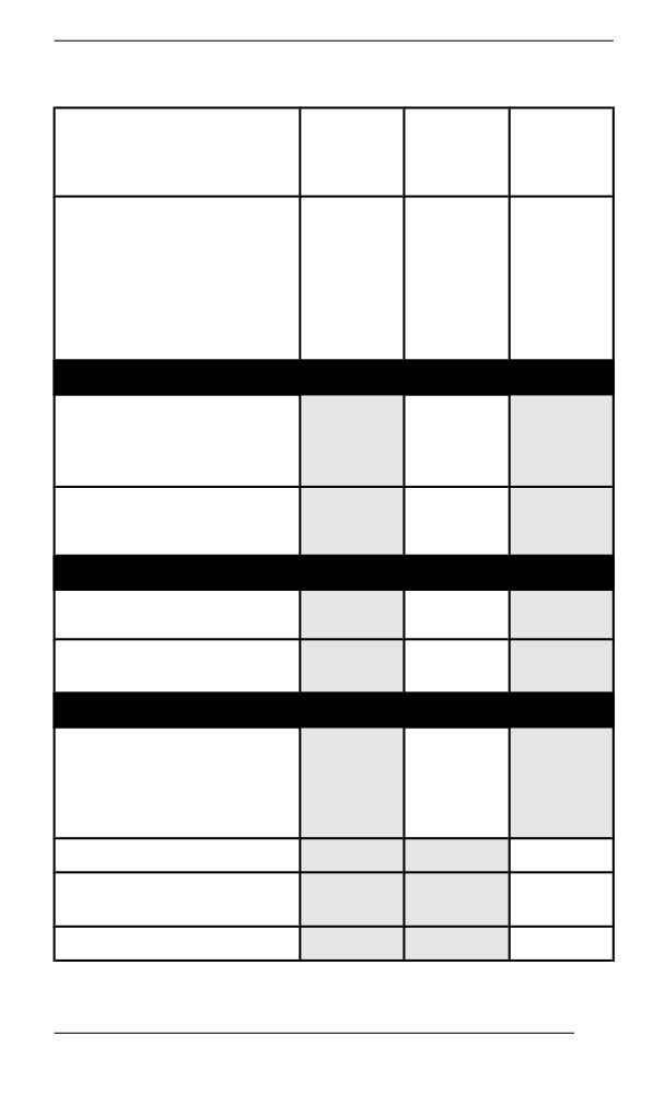
E-TEC Engine (except turbo)
TRAIL /
CROSSOVER
A+
A
B
/ UTILITY
Every
Every 2
A=Adjust
Every
month
years
C=Clean
year
or
or
I=Inspect
or
1500
6000
L=Lubricate
3000 km
km
km
R=Replace
(2000
(1000
(4000
T=Torque
mi)
mi)
mi)
Air and Fuel Delivery
Fuel components (fuel
cap, hoses, clamps and
I
tank fixation) and
function
R
In-line fuel filter
Every 5
years
Body and Chassis
Body panels and
I, T
hardware
Pivots, latches, hinges
L
and key barrels
Engine and Cooling
Engine cooling
components (coolant
concentration, coolant
I, A
level, hose condition,
clamps, leaks)
Engine rubber mounts
I
Rewind starter (manual
C, L
start models)
Spark plugs
R
201
MAINTENANCE SCHEDULE
TRAIL /
CROSSOVER
A+
A
B
/ UTILITY
Every
Every 2
A=Adjust
Every
month
years
C=Clean
year
or
or
I=Inspect
or
1500
6000
L=Lubricate
3000 km
km
km
R=Replace
(2000
(1000
(4000
T=Torque
mi)
mi)
mi)
Every 3
years
or
10 000
km
(6000
mi)
I, C
Every 3
years
Oil injection pump
or
10 000
strainer
km
(6000
mi)
I, C
Every 3
years
or
RAVE valves
10 000
km
(6000
mi)
R
Engine coolant
Every 5
years
Exhaust and Emissions
Exhaust components
(gaskets, pipes, muffler
I
condition, leaks)
202
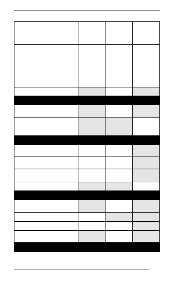
MAINTENANCE SCHEDULE
TRAIL /
CROSSOVER
A+
A
B
/ UTILITY
Every
Every 2
A=Adjust
Every
month
years
C=Clean
year
or
or
I=Inspect
or
1500
6000
L=Lubricate
3000 km
km
km
R=Replace
(2000
(1000
(4000
T=Torque
mi)
mi)
mi)
Exhaust manifold
T
Brake
Brake components and
I, L
function
R
Brake fluid
Every 2
years
Drive
Chaincase drive chain
A
A
tension
Gearbox / chaincase oil
I
I
level
Track alignment and
A
I, A
tension
Gearbox / chaincase oil
R
Continuously Variable Transmission (CVT)
CVT components and
I, C, L
function
CVT drive belt condition
I
CVT drive belt tension
A
A
Drive pulley retaining
T
screw
Electrical
203
MAINTENANCE SCHEDULE
TRAIL /
CROSSOVER
A+
A
B
/ UTILITY
Every
Every 2
A=Adjust
Every
month
years
C=Clean
year
or
or
I=Inspect
or
1500
6000
L=Lubricate
3000 km
km
km
R=Replace
(2000
(1000
(4000
T=Torque
mi)
mi)
mi)
Battery connections and
I
condition
Electrical harness
I
routing
Headlight aim
A
Modules and applicable
I
software updates
Operation of control
I
switches and lighting
Steering and Controls
Ski runners
I
I
Gearbox position lever
I, A
operation
Steering alignment
I, A
Steering components
I
and function
Throttle cable
A
Throttle operation
I
Suspension
Suspension components
I, L
and function
Rear suspension limiter
R
strap
204
MAINTENANCE SCHEDULE
205
MAINTENANCE SCHEDULE
DEEP SNOW
A+
A
B
Every 2
A=Adjust
Every
Every
years
C=Clean
month
year
or
I=Inspect
or
or
6000
L=Lubricate
1500 km
3000 km
km
R=Replace
(1000
(2000
(4000
T=Torque
mi)
mi)
mi)
Air and Fuel Delivery
Fuel components (fuel
cap, hoses, clamps and
I
tank fixation) and
function
R
In-line fuel filter
Every 5
years
Body and Chassis
Body panels and
I, T
hardware
Pivots, latches, hinges
L
and key barrels
Engine and Cooling
Engine cooling
components (coolant
concentration, coolant
I, A
level, hose condition,
clamps, leaks)
Engine rubber mounts
I
Rewind starter (manual
C, L
start models)
R
Every 3
years
Spark plugs
or
10 000
km
206
MAINTENANCE SCHEDULE
DEEP SNOW
A+
A
B
Every 2
A=Adjust
Every
Every
years
C=Clean
month
year
or
I=Inspect
or
or
6000
L=Lubricate
1500 km
3000 km
km
R=Replace
(1000
(2000
(4000
T=Torque
mi)
mi)
mi)
(6000
mi)
I, C
Every 3
years
Oil injection pump
or
strainer
10 000
km
(6000
mi)
I, C
Every 3
years
or
RAVE valves
10 000
km
(6000
mi)
R
Engine coolant
Every 5
years
Exhaust and Emissions
Exhaust components
(gaskets, pipes, muffler
I
condition, leaks)
Exhaust manifold
T
Brake
Brake components and
I, L
function
207

MAINTENANCE SCHEDULE
DEEP SNOW
A+
A
B
Every 2
A=Adjust
Every
Every
years
C=Clean
month
year
or
I=Inspect
or
or
6000
L=Lubricate
1500 km
3000 km
km
R=Replace
(1000
(2000
(4000
T=Torque
mi)
mi)
mi)
R
Brake fluid
Every 2
years
Drive
A
After the
first
75 km
(50 mi)
then
every
Chaincase drive chain
500 km
A
tension
(300 mi),
up to
then
every
1500 km
(1000
mi)
Gearbox / chaincase oil
I
level
A
After the
first
75 km
(50 mi)
Track alignment and
then
I, A
every
tension
500 km
(300 mi),
up to
then
every
208
MAINTENANCE SCHEDULE
DEEP SNOW
A+
A
B
Every 2
A=Adjust
Every
Every
years
C=Clean
month
year
or
I=Inspect
or
or
6000
L=Lubricate
1500 km
3000 km
km
R=Replace
(1000
(2000
(4000
T=Torque
mi)
mi)
mi)
1500 km
(1000
mi)
Gearbox / chaincase oil
R
Continuously Variable Transmission (CVT)
CVT components and
I,
C, L
function
CVT drive belt condition
I
CVT drive belt tension
A
A
Drive pulley retaining
T
screw
Electrical
Battery connections and
I
condition
Electrical harness
I
routing
Headlight aim
A
Modules and applicable
I
software updates
Operation of control
I
switches and lighting
Steering and Controls
Ski runners
I
Gearbox position lever
I, A
operation
209
MAINTENANCE SCHEDULE
DEEP SNOW
A+
A
B
Every 2
A=Adjust
Every
Every
years
C=Clean
month
year
or
I=Inspect
or
or
6000
L=Lubricate
1500 km
3000 km
km
R=Replace
(1000
(2000
(4000
T=Torque
mi)
mi)
mi)
Steering alignment
I, A
Steering components
I
and function
Throttle cable
A
Throttle operation
I
Suspension
Suspension components
I, L
and function
Rear suspension limiter
R
strap
210
MAINTENANCE PROCEDURES
This section includes instructions for basic maintenance procedures.
WARNING
Turn off the engine, remove tether cord cap and follow these
maintenance procedures when performing maintenance. If you
do not follow proper maintenance procedures you can be in-
jured by hot parts, moving parts, electricity, chemicals or other
hazards.
WARNING
Should removal of a locking device be required (e.g. lock tabs,
self-locking fasteners, etc.) when undergoing disassembly/as-
sembly, always replace with a new one.
Engine Coollant
WARNING
Never open coolant tank cap when engine is hot.
Verifying the Engine Coolant Level
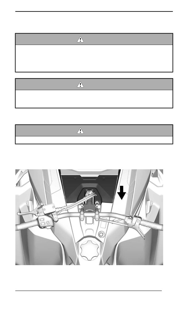
1. Remove access panel.
2. Check coolant level at room temperature. Liquid should touch the
flat surface of the eyesight.
211
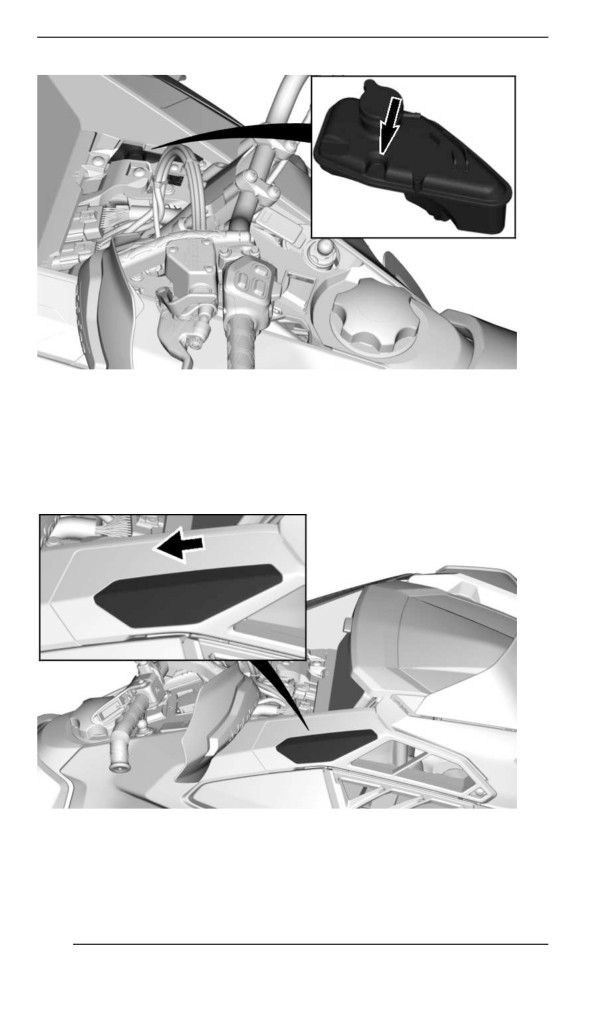
MAINTENANCE PROCEDURES
3. Add coolant if required.
NOTE:
When checking level at low temperature it may be slightly lower than
the mark.
4. Slide the air intake filter cap rearwards to unlock, then remove.
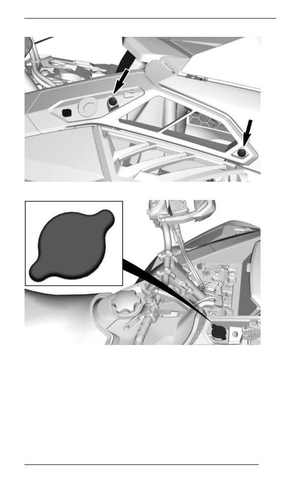
5. Remove the following fasteners then the RH air filter.
212
MAINTENANCE PROCEDURES
6. Add coolant by the filler neck.
7. If coolant level keeps dropping during or after each ride or if entire
system has to be refilled, refer to an authorized BRP snowmobile
dealer, repair shop or person of your own choosing for servicing.
213
MAINTENANCE PROCEDURES
Recommended Engine Coolant
RECOMMENDED COOLANT
XPS Extended life pre-mixed coolant
IF THE RECOMMENDED XPS COOLANT IS NOT
AVAILABLE
Distilled water and antifreeze solution (50% distilled water, 50%
antifreeze)
NOTICE
Always use ethylene-glycol antifreeze containing corrosion in-
hibitors specifically for internal combustion aluminum engines.
Exhaust System
Exhaust System Verification
The muffler tail pipe should be centered with the exit hole in the bottom
pan. Exhaust system must be free of rust or leaks. Make sure that all
parts are securely in place.
Check retaining springs and heat shields condition and replace if
necessary.
The exhaust system is designed to reduce noise and to improve the
total performance of the engine. Modification may be in violation of lo-
cal laws.
NOTICE
If any exhaust system component is removed, modified or dam-
aged, severe engine damage may result.
Spark Pllugs
Spark plugs inspection or replacement may be performed by an au-
thorized BRP snowmobile dealer, repair shop, or person of your own
choosing. Spark plugs inspection or replacement requires an in-depth
technical knowledge. Though not required, it is recommended that an
authorized BRP snowmobile dealer performs spark plugs inspection
or replacement.
214
MAINTENANCE PROCEDURES
Brake Fluid
Verifying the Brake Fluid Level
NOTICE
Vehicle must be on a level surface before checking any fluid
levels.
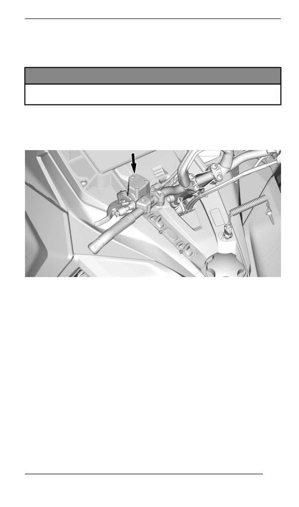
1. Position the handlebar in the straight-ahead position to ensure the
reservoir is level.
2. Check brake fluid in the reservoir for proper level.
TYPICAL
Brake fluid must always be above the bottom of the window when
brake lever is squeezed.
215
MAINTENANCE PROCEDURES
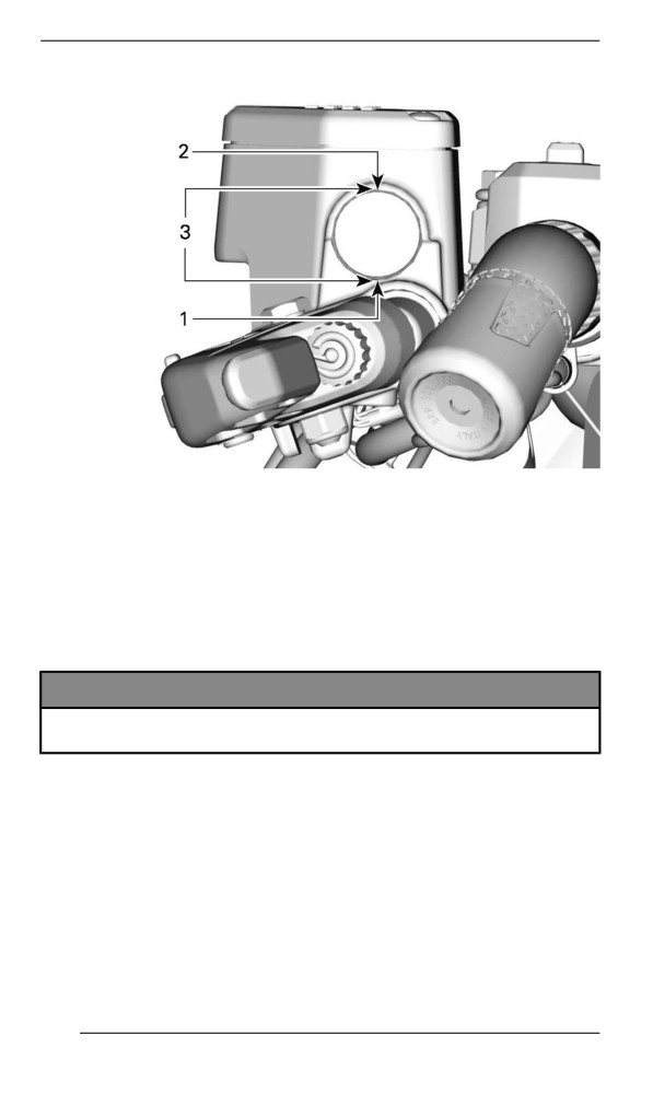
TYPICAL
1. Minimum
2. Maximum
3. Operating range
If brake fluid level keeps dropping during or after each ride, or if en-
tire system has to be refilled, refer to an authorized BRP dealer, re-
pair shop, or a person of your own choosing for servicing.
Adding Brake Fluid
NOTICE
Vehicle must be on a level surface before checking any fluid
levels.
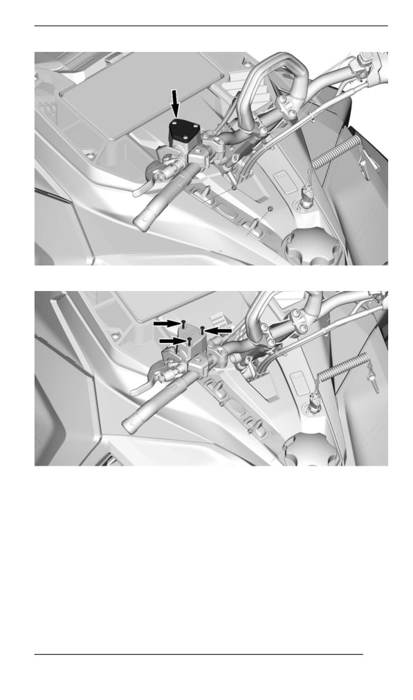
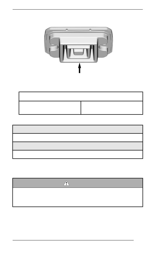
1. Clean the reservoir cap.
216
MAINTENANCE PROCEDURES
2. Remove the screws retaining the reservoir cap.
3. Remove the reservoir cap.
217
MAINTENANCE PROCEDURES
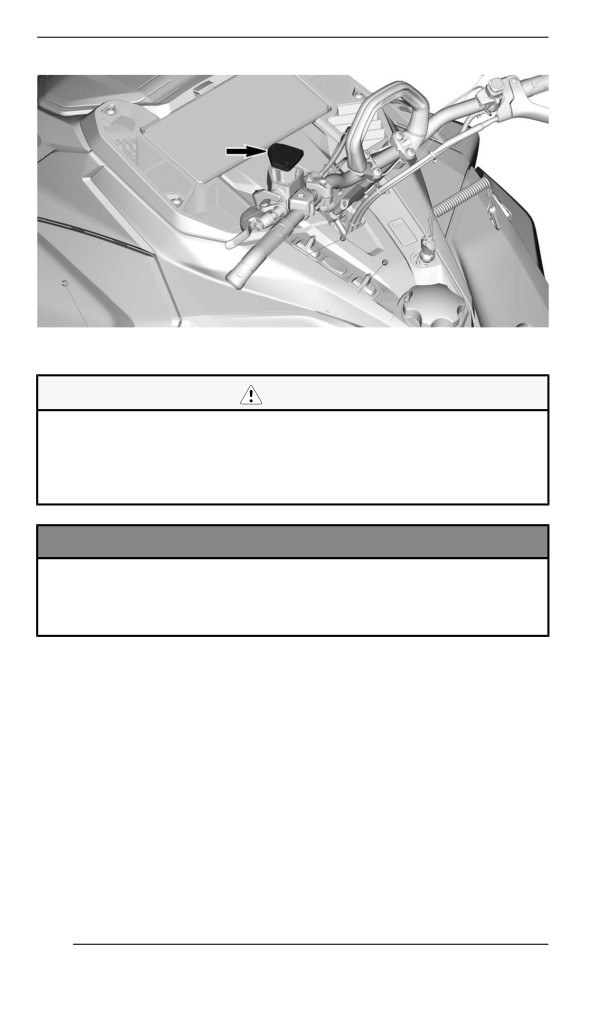
4. Add fluid as required. Do not overfill. Use only the recommended
brake fluid. Refer to Recommended Brake Fluid in this subsection.
CAUTION
Avoid getting brake fluid on skin or eyes - it may cause severe
burns. In case of contact with the skin, wash thoroughly. In
case of contact with the eyes, immediately rinse with plenty of
water for at least 10 minutes and then consult a doctor
immediately.
NOTICE
– Brake fluid can damage paint, rubber and plastic parts
– Protect these nearby parts with a rag when servicing the
brake system
– Rinse thoroughly in case of spillage.
5. Ensure the diaphragm is pushed in the reservoir cap before instal-
ling the cap one the reservoir.
218
MAINTENANCE PROCEDURES
6. Reinstall reservoir cap and screws. Tighten to specification.
Tightening Torque
0.7 ± 0.1 Nm
Reservoir cap screws
(6 ± 1 lbf-in)
Recommended Brake Fluid
Recommended Brake Fluid
XPS DOT 4 Brake Fluid
Alternative or if not available
DOT 4 Brake Fluid
Use only DOT 4 brake fluid from a sealed container. An opened con-
tainer may be contaminated or may have absorbed moisture from the
air.
WARNING
Use only DOT 4 brake fluid from a sealed container. To avoid
serious damage to the braking system, do not use fluids other
than the recommended one, nor mix different fluids for topping
up.
219
MAINTENANCE PROCEDURES
Chaiincase Oill
Recommended Chaincase Oil
Recommended Chaincase Oil
XPS Synthetic chaincase oil
Alternative or if not available
75W140 gear oil that meets the API GL-5 specification
NOTICE
If the recommended XPS chaincase oil is not available, use a
75W140 gear oil that meets the API GL-5 specification. The
chaincase of this snowmobile has been developed and vali-
dated using the XPS™ Synthetic chaincase oil. BRP strongly
recommends the use of its XPS Synthetic chaincase oil at all
times. Damages caused by oil which is not suitable for the
chaincase will not be covered by the BRP limited warranty.
Verifying the Chaincase Oil Level
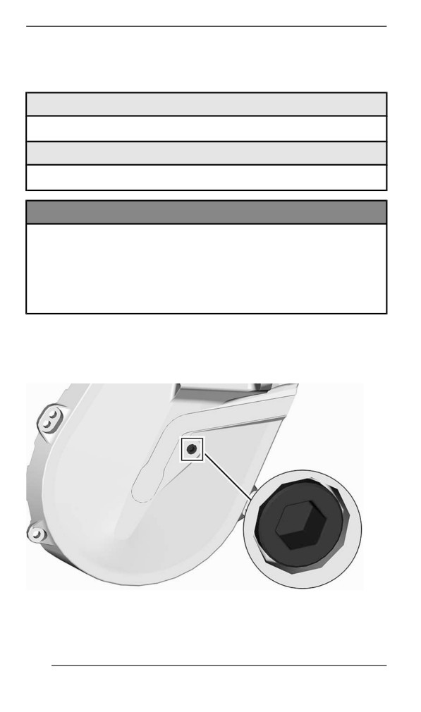
With the vehicle on a level surface, check the oil level by removing the
check plug.
CHECK PLUG
Oil level must reach the threaded hole.
220
MAINTENANCE PROCEDURES
If level is correct, reinstall check plug and tighten to the specified
torque.
Tightening Torque
Check plug
6 ± 1 Nm (53 ± 9 lbf-in)
If level is insufficient, refer to Chaincase Filling Procedure.
Replacing the Chaincase Oil
Draiining the Chaiincase Oiil
1. Place the vehicle on a level surface.
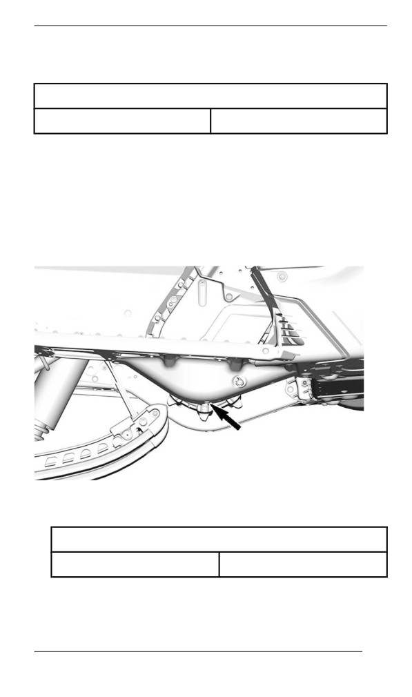
2. Place a drain pan under the chaincase drain plug area.
3. Remove filler cap.
4. Remove the drain plug located at the bottom of the chaincase.
5. Wait a while to allow all oil to drain out of the chaincase.
6. Install drain plug and tighten to specification.
Tightening Torque
Chaincase drain plug
6 ± 1 Nm (53 ± 9 lbf-in)
Fillliing the Chaiincase
1. Open the RH side panel. Refer to Equipment.
221
MAINTENANCE PROCEDURES
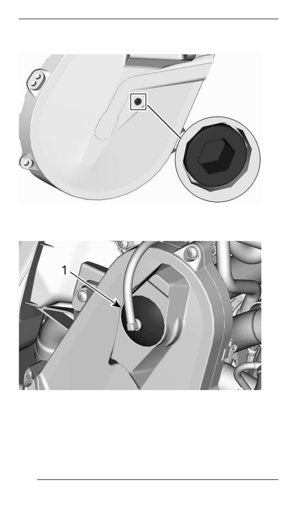
2. Remove the check plug.
CHECK PLUG
3. Remove the filler cap.
TYPICAL - TOP OF CHAINCASE
1. Filler cap
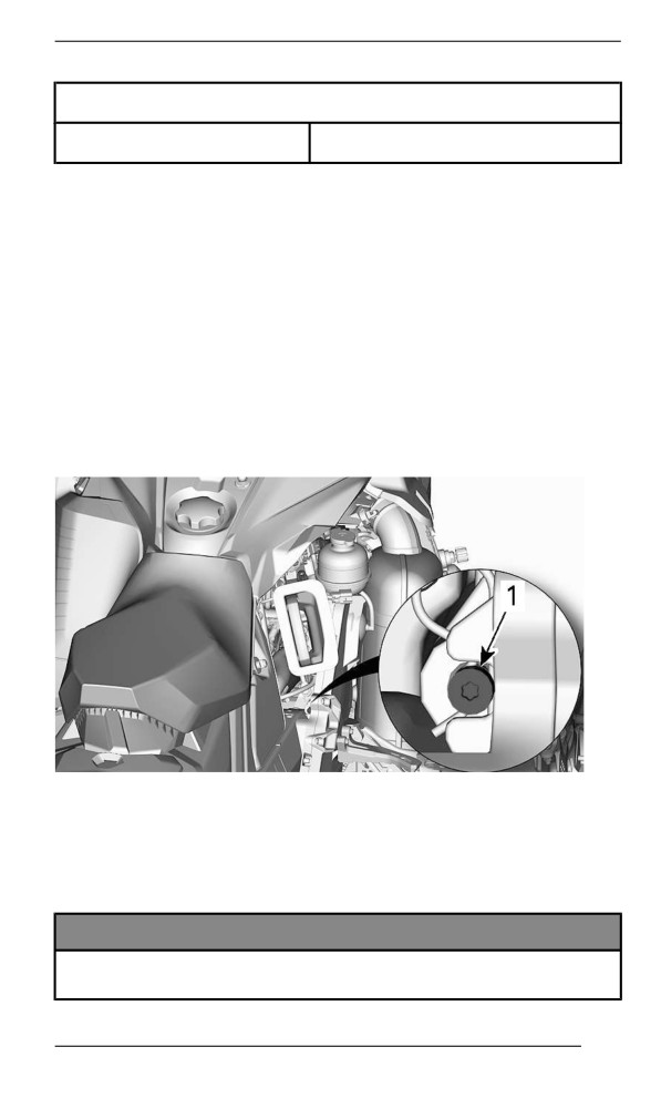
4. Pour recommended oil in the filler hole until oil comes out by the
check plug hole.
5. Reinstall check plug and tighten to specification.
222
MAINTENANCE PROCEDURES
Tightening Torque
Check plug
6 ± 1 Nm (53 ± 9 lbf-in)
Reinstall the filler cap.
Driive Chain
Access to Chaincase
Open RH side panel, refer to Equipment.
Drive Chain Adjustment
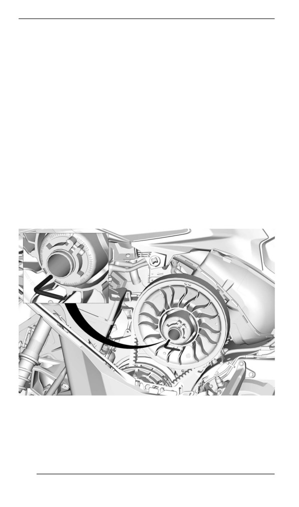
Using the Torx end of the driven pulley expander, GENTLY turn ten-
sioner clockwise to eliminate the play.
NOTE: Make sure the play is completely eliminated by trying to turn
back and forth the driven pulley.
TYPICAL
Do not force the tensioner in.
NOTE:
Do not remove the hair cotter pin.
NOTICE
Overtightening the drive chain could result in severe damage to
the chaincase components.
223
MAINTENANCE PROCEDURES
Drive Belt
Drive Belt Inspection
Remove the drive belt guard. Refer to the procedure in Equipment.
Inspect belt for cracks, fraying or abnormal wear (uneven wear, wear
on one side, missing cogs, cracked fabric). If abnormal wear is noted,
probable cause could be pulley misalignment, excessive RPM with
frozen track, fast starts without warm-up period, burred or rusty
sheave, oil on belt or distorted spare belt. Contact an authorized BRP
snowmobile dealer.
Replacing the Drive Belt
Removiing the Driive Belt
1. Remove the tether cord cap from engine cut-off switch.
2. Remove the LH side panel.
3. Remove the drive belt guard. Refer to Removing the Drive Belt
Guard.
4. Insert the driven pulley expander provided, in the threaded hole on
the adjuster hub as shown.
TYPICAL - PULLEY EXPANDER INSTALLED ON ADJUSTER
HUB
5. Open the driven pulley by screwing the tool in.
6. Remove the drive belt by slipping it over the edge of the driven pul-
ley, then over the drive pulley.
224
MAINTENANCE PROCEDURES
Installliing the Drive Belt
The driven pulley must be expanded. Refer to Removing the Drive
Belt.
1. Slip the belt over the drive pulley, then over the driven pulley.
NOTICE
Do not force or use tools to pry the belt into place, as this could
cut or break the cords in the belt.
NOTE:
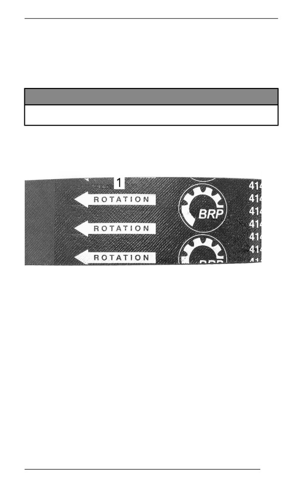
The maximum drive belt life span is obtained when belt is installed
with arrows in the direction of rotation.
1. To be pointed in the direction of rotation
2. Unscrew and remove the driven pulley expander from the pulley.
3. Rotate the driven pulley several times to properly set the belt be-
tween the sheaves.
4. If a new belt was installed, an adjustment will be required for the
proper belt height. Refer to Adjusting the Drive Belt Height.
5. Install belt guard.
6. Close side panel.
Adjusting the Drive Belt Height
Remove the tether cord cap from engine cut-off switch.
Remove the LH side panel.
Remove the drive belt guard.
The drive belt height must be checked every time a new drive belt is
installed and as part of the pre-ride inspection.
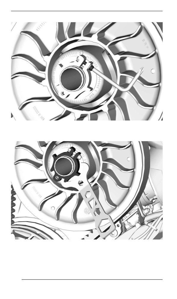
1. Loosen the clamping screw.
225
MAINTENANCE PROCEDURES
2. Using the suspension adjustment tool provided in the tool kit, turn
the adjustment ring 1/4 turn at a time then rotate the driven pulley
to properly set the belt between the pulley sheaves.
NOTE:
The adjustment ring has left hand treads.
226
MAINTENANCE PROCEDURES
600R E-TEC
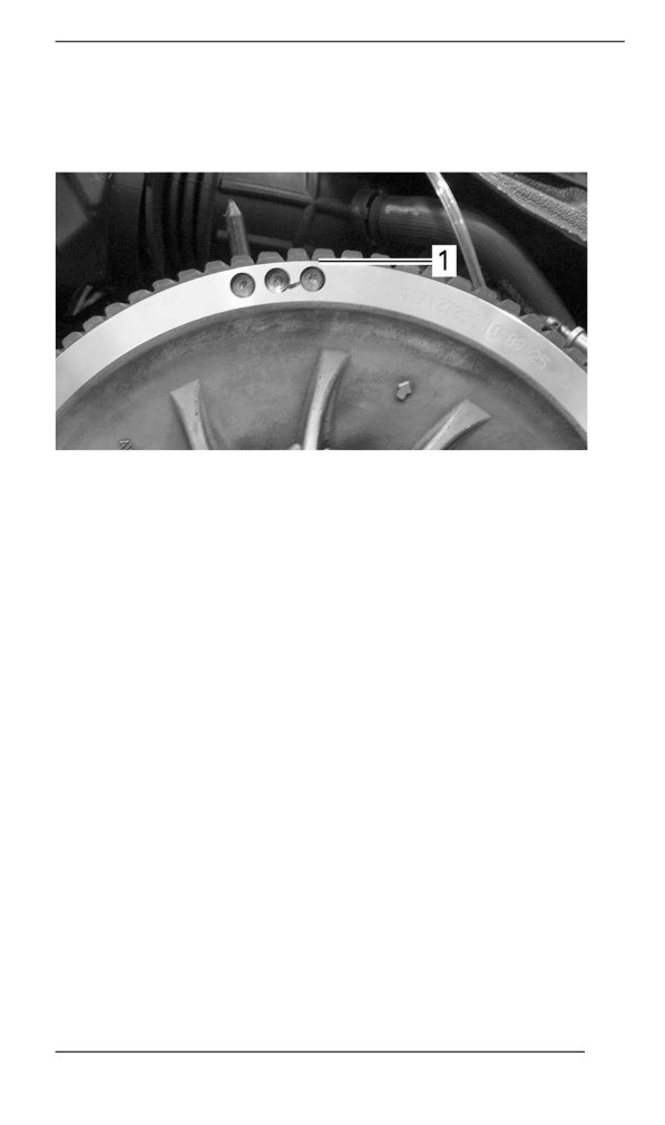
Repeat step 4 until the lowest portion of the cogs on the external
surface of drive belt is even with the driven pulley edge.
PRELIMINARY SETTING
1. Lowest portion of cogs even with external surface of drive belt
850 E-TEC
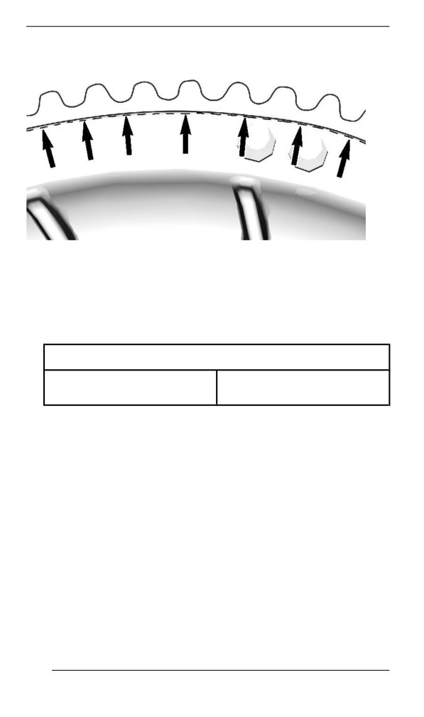
Repeat step 5 until the cord of drive belt is just hidden by the driven
pulley edge.
227
MAINTENANCE PROCEDURES
PRELIMINARY SETTING
NOTE:
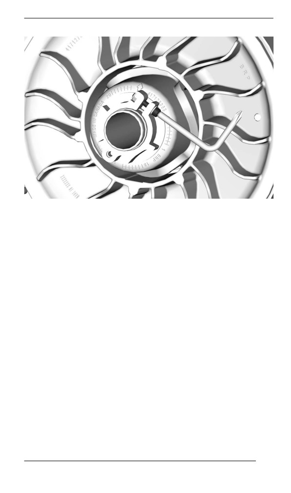
Turning the adjustment ring counterclockwise lowers the belt in the
pulley. Turning the ring clockwise raises the belt in the pulley.
3. Tighten the adjustment ring clamping screw.
Tightening Torque
Adjustment ring clamping
5.5 ± 0.5 Nm (49 ± 4 lbf-in)
screw
228
MAINTENANCE PROCEDURES
4. Install belt guard, refer to Installing the Drive Belt Guard.
5. Install LH side panel.
6. Start engine and check if vehicle creeps.
7. If vehicle does not creep, adjustment is complete.
8. If vehicle creeps, check the drive belt deflection.
Reverse Activation (if equiipped)
Reverse may not activate or may be harder to activate if the belt is
positioned too high in the driven pulley. If reverse activation does not
work properly, ensure the drive belt is properly adjusted.
Adjust the drive belt lower in the driven pulley if needed.
229
MAINTENANCE PROCEDURES
Drive Pulley
Drive Pulley Adjustment (if equipped)
WARNING
Remove tether cord cap from engine cut-off switch before per-
forming any adjustment. Vehicle must be parked in a safe
place, away from the trail.
WARNING
NEVER disassemble or modify the drive pulley.
Improper assembly or modifications could cause the pulley to
explode violently under the stress generated by the high rota-
tional speed.
Visit your BRP snowmobile dealer to maintain or service the
drive pulley. Improper servicing or maintenance may affect per-
formance and reduce belt life. Always respect maintenance
schedules.
The drive pulley is factory calibrated to transmit maximum engine
power at a predefined RPM. Factors such as ambient temperature, al-
titude or surface condition may vary this critical engine RPM thus af-
fecting snowmobile efficiency.
This adjustable drive pulley allows setting maximum engine RPM to
maintain maximum power.
Ramp cams should be adjusted so that actual maximum engine RPM
matches the maximum horsepower RPM. Refer to Technical Specifi-
cations (Engine).
NOTE:
Use a precision digital tachometer for engine RPM adjustment.
There are 5 positions in which the ramp cam can be set.
Each position modifies the maximum engine RPM by about 200 RPM.
Lower position numbers decrease engine RPM in steps of 200 RPM
and higher position numbers increase it in steps of 200 RPM.
Procedure
1. Refer to Body and Seat in Vehicle Information and remove:
- LH side panel
- Drive pulley guard
230
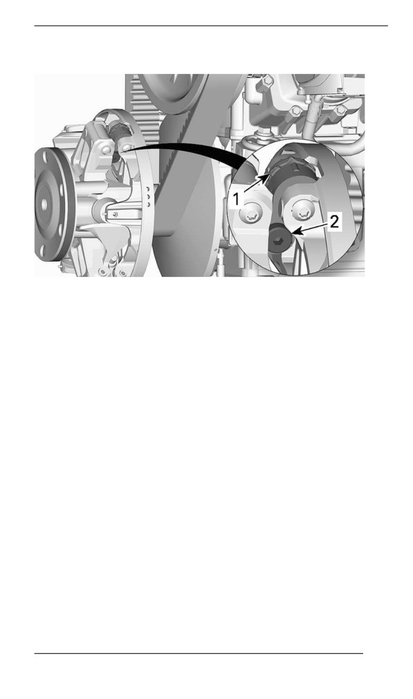
MAINTENANCE PROCEDURES
2. Locate the cam and the pivot screw on the drive pulley.
TYPICAL
1. Cam
2. Pivot screw
The cam position is identified as follows:
- Positions 1, 2, 4 and 5 are numbered.
- Position 3 (middle) is identified by a notch.
- There are notches on each side of the cam used as pointers.
231
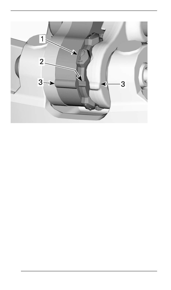
MAINTENANCE PROCEDURES
1. Numbered position
2. Position 3 - Notch
3. Pointers
To adjust, proceed as follows for all 3 cams:
3. Using the Allen end of the driven pulley expander, loosen the pivot
screw.
232
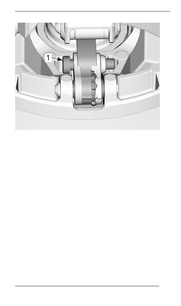
MAINTENANCE PROCEDURES
1. Pivot screw
4. Move the right lever aside to be able to turn the cam.
5. Turn cam to the desired position.
233
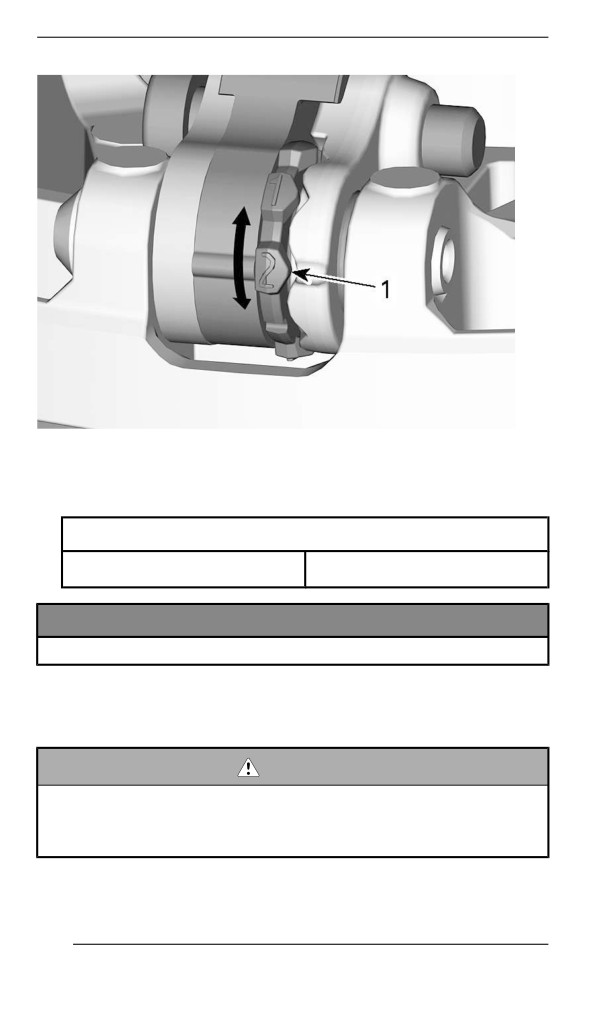
MAINTENANCE PROCEDURES
1. Desired cam position (here #2)
6. Tighten the pivot screw.
TIGHTENING TORQUE
Pivot
8 ± 1 Nm (71 ± 9 lbf-in)
NOTICE
Always adjust all 3 cams to the same setting.
Track
Track Condition
WARNING
Remove tether cord cap from engine cut-off switch before per-
forming any maintenance or adjustment, unless otherwise
specified. Vehicle must be parked in a safe place, away from
the trail.
Remove tether cord cap from engine cut-off switch.
234
MAINTENANCE PROCEDURES
Lift the rear of the snowmobile and support it with a wide-base snow-
mobile mechanical stand with a rear deflector panel. With the engine
off, rotate the track by hand, and inspect condition. If worn or cut, or if
track fibers are exposed, or if missing or defective inserts or guides
are noted; contact an authorized BRP snowmobile dealer.
Snowmobiles Equipped with Traction Enhancing Products
If your snowmobile is equipped with a BRP approved studded track,
PROCEED WITH A VISUAL INSPECTION OF YOUR TRACK BE-
FORE EACH USE.
Look for any defects, such as:
- Perforations in the track
- Tears in the track (particularly around traction holes on studded
tracks)
- Lugs that are broken or torn off, exposing portions of rods
- Delamination of the rubber
- Broken rods
- Broken studs (studded tracks)
- Bent studs (studded tracks)
- Missing studs
- Studs that are torn off the track
- Missing track guide(s)
- Also, ensure that studs nut are tighten to the recommended
torque.
On approved studded tracks, replace broken or damaged studs imme-
diately. If your track shows signs of deterioration, it must be replaced
immediately. When in doubt, ask your dealer.
WARNING
Riding with a damaged track or studs could lead to a loss of
control.
For complete information on traction enhancing products, refer to
TRACTION ENHANCING PRODUCTS in SAFETY INFORMATION at
the beginning of this Operator's Guide.
Track Tension and Alignment
NOTE:
Track tension and alignment are interrelated. Do not adjust one with-
out the other.
235
MAINTENANCE PROCEDURES
WARNING
To prevent serious injury to individuals near the snowmobile:
– NEVER stand behind or near a moving track.
– Always use a wide-base snowmobile stand with a rear de-
flector panel if it is necessary to rotate track.
– When the track is raised off the ground, only run it at the low-
est possible speed.
Centrifugal force could cause debris, damaged or loose studs,
pieces of torn track, or an entire severed track to be violently
thrown backwards out of the tunnel with tremendous force, pos-
sibly resulting in the loss of a leg or other serious injury.
Veriifyiing the Track Tension
NOTE:
Ride the snowmobile in snow about 15 to 20 minutes prior to adjusting
track tension.
1. Remove tether cord cap from engine cut-off switch.
2. Lift rear of vehicle and support it off the ground.
CAUTION
Use proper lifting techniques, notably using your legs force. Do
not attempt to lift the rear of vehicle if it is above your limits.
3. Allow rear suspension to fully extend.
4. Prepare the tensiometer.
Service tool
Tensiometer (P/N 414348200)
1. Set the bottom O-ring as per the Track Deflection from the ap-
plicable vehicle in the Technical Specifications table.
236
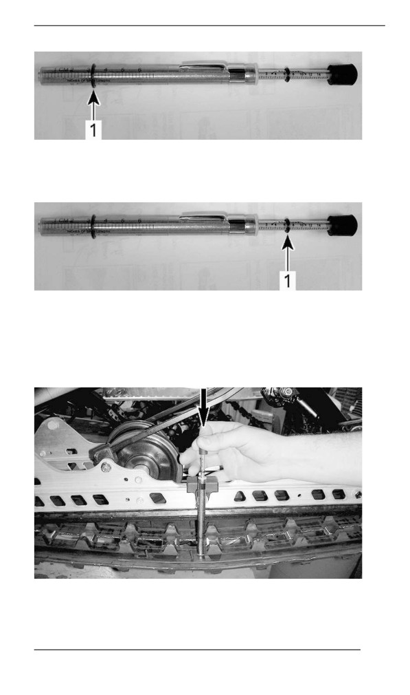
MAINTENANCE PROCEDURES
1. Bottom O-ring
2. Place the upper O-ring to 0 kgf (0 lbf).
1. Upper O-ring
5. Position the tensiometer on track, halfway between front and rear
idler wheels.
6. Push the tensiometer downwards until bottom O-ring (deflection
set earlier) be aligned with the bottom of slider shoe.
TYPICAL
237
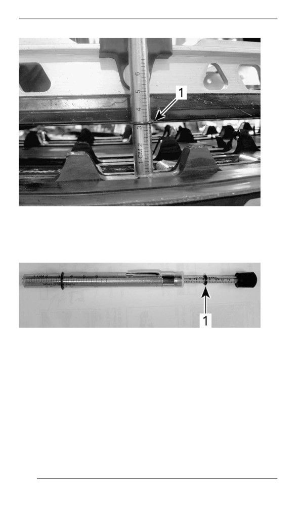
MAINTENANCE PROCEDURES
TYPICAL
1. Deflection O-ring aligned with slider shoe
7. Read load recorded by the upper O-ring on the tensiometer.
TYPICAL - LOAD READING
1. Upper O-ring
8. Load reading must be as per the track deflection in the Technical
Specifications.
9. If load reading is not in accordance with the specification, adjust
track tension. Refer to Track Tension Adjustment.
Adjjusting the Track Tensiion - PPS3 Suspensiion
1. Remove tether cord cap from engine cut-off switch.
2. Lift rear of vehicle and support it off the ground.
238
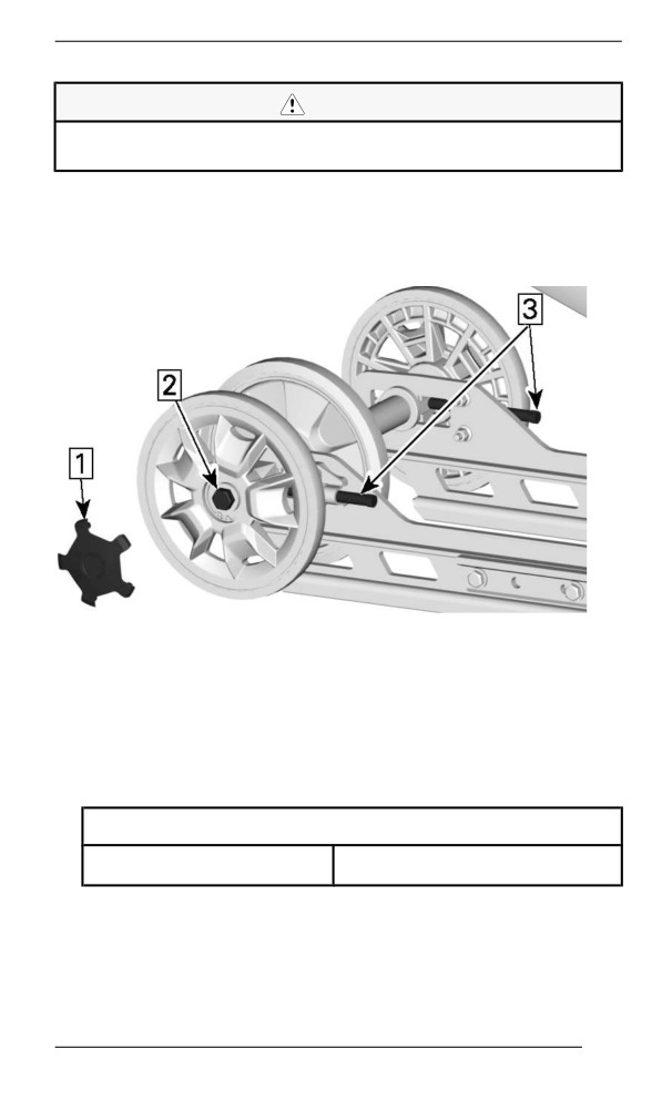
MAINTENANCE PROCEDURES
CAUTION
Use proper lifting techniques, notably using your legs force. Do
not attempt to lift the rear of vehicle if it is above your limits.
3. Remove wheel cap.
4. Loosen the rear axle screws.
5. Loosen or tighten both adjustment screws (equally) to decrease or
increase track tension.
PPS3
1. Remove wheel cap
2. Loosen the axle screw
3. Loosen or tighten the adjustment screws
6. If correct tension is unattainable, contact an authorized Lynx
dealer.
7. Retighten the rear axle nut to specification.
TIGHTENING TORQUE
Rear idler wheel screw
48 ± 6 Nm (35 ± 4 lbf-ft)
8. Check track alignment as described below.
239
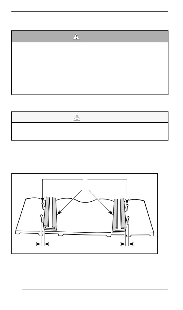
MAINTENANCE PROCEDURES
Aliigniing the Track
WARNING
Before checking track alignment, ensure that the track is free of
all particles which could be thrown out while track is rotating.
Keep hands, tools, feet and clothing clear of track. Always lift
the snowmobile on a wide-base stand with a rear deflector pan-
el. Ensure no one is standing in close proximity to the snowmo-
bile, especially at the rear of the track. Never rotate track at
high speed.
Centrifugal force could cause debris, damaged or loose studs,
pieces of torn track, or an entire severed track to be violently
thrown backwards out of the tunnel with tremendous force.
1. Lift rear of vehicle and support it off the ground.
CAUTION
Use proper lifting techniques, notably by using the force of your
legs . Do not attempt to lift the rear of vehicle if it is above your
limits.
2. Start engine and accelerate slightly so that track slowly turns. This
must be done in a short period of time (15 to 20 seconds).
3. Check that the track is well centered; equal distance on both sides
between edges of track guides and slider shoes.
1
2
3
A01F05A
1. Guides
2. Slider shoes
3. Equal distance
240
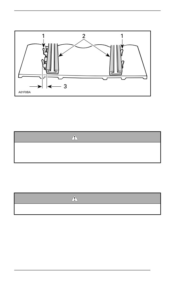
MAINTENANCE PROCEDURES
4. To correct track alignment:
1. Guides
2. Slider shoes
3. Tighten on this side
1. Stop engine.
2. Remove tether cord cap from engine cut-off switch.
WARNING
Remove tether cord cap from engine cut-off switch before per-
forming any maintenance or adjustment, unless otherwise
specified. Vehicle must be parked in a safe place, away from
the trail.
3. Loosen the rear axle nut.
4. Tighten adjustment screw on side where the slider shoe is the
farthest from the track insert guides.
5. Tighten the rear axle nut.
WARNING
Properly tighten wheel retaining bolt, otherwise wheel may
come off and cause track to “lock”.
6. Restart engine and rotate track slowly to recheck alignment.
7. Tighten the rear axle nut to specified torque.
241
MAINTENANCE PROCEDURES
Tightening Torque
Rear axle screw
48 ± 6 Nm (35 ± 4 lbf-ft)
8. Reposition snowmobile on the ground.
Suspensiion
Steering and Front Suspension Condition
Visually inspect steering and front suspension for tightness of compo-
nents (steering arms, control arms and links, tie rods, ball joints, ski
bolts, ski legs, etc.). If necessary, contact an authorized BRP snowmo-
bile dealer.
Suspension Stopper Strap Condition
Inspect stopper straps for wear and cracks, bolt and nut for tightness.
If loose inspect holes for deformation. Replace as required. Tighten
nut to specification.
Tightening Torque
Stopper strap nut
7 ± 1 Nm (62 ± 9 lbf-in)
Rear Suspension Condition
Visually inspect all suspension components including slider shoes,
springs, wheels, etc.
NOTE:
During normal driving, snow will act as a lubricant and coolant for the
slider shoes. Extensive riding on ice or sanded snow, will create ex-
cessive heat build-up and cause premature slider shoe wear.
Suspension Lubrication – PPS
Lubricate the following suspension pivots at grease fittings. Refer to
MAINTENANCE SCHEDULE for maintenance frequency.
SUSPENSION GREASE
XPS Synthetic suspension grease
242
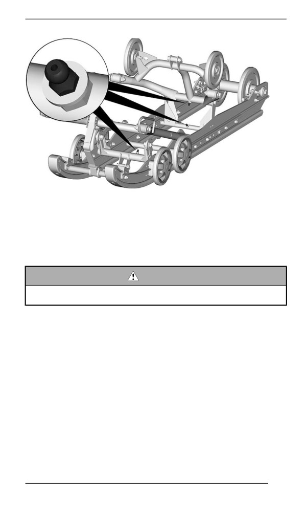
MAINTENANCE PROCEDURES
TYPICAL
Skis
Wear and Condition of Skis and Runners
Check the condition of the skis and ski runner carbides. If worn, con-
tact an authorized BRP snowmobile dealer.
WARNING
Excessively worn skis and/or ski runners will adversely affect
snowmobile control.
Fuses
Access to Fuse Block
Open RH side panel, refer to Body and Seat.
243
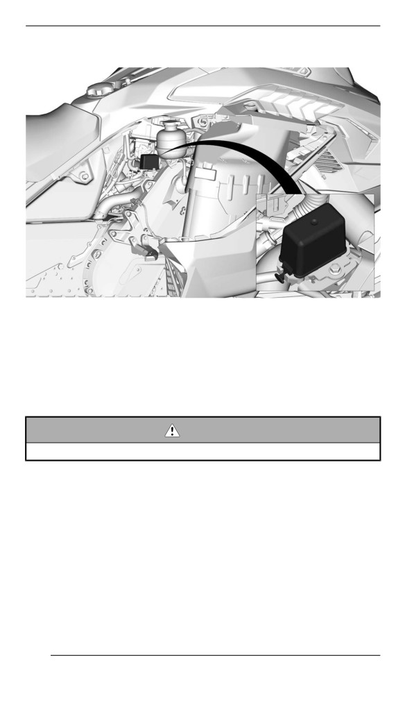
MAINTENANCE PROCEDURES
Fuses Location
TYPICAL
Remove the fuse box cover.
Refer to Technical Specifications for fuse rate and configuration.
Inspecting a Fuse
Check fuse condition and replace it if necessary.
WARNING
Never use a higher rated fuse than specified.
To remove fuse from holder, pull fuse out. Check if filament is melted.
244
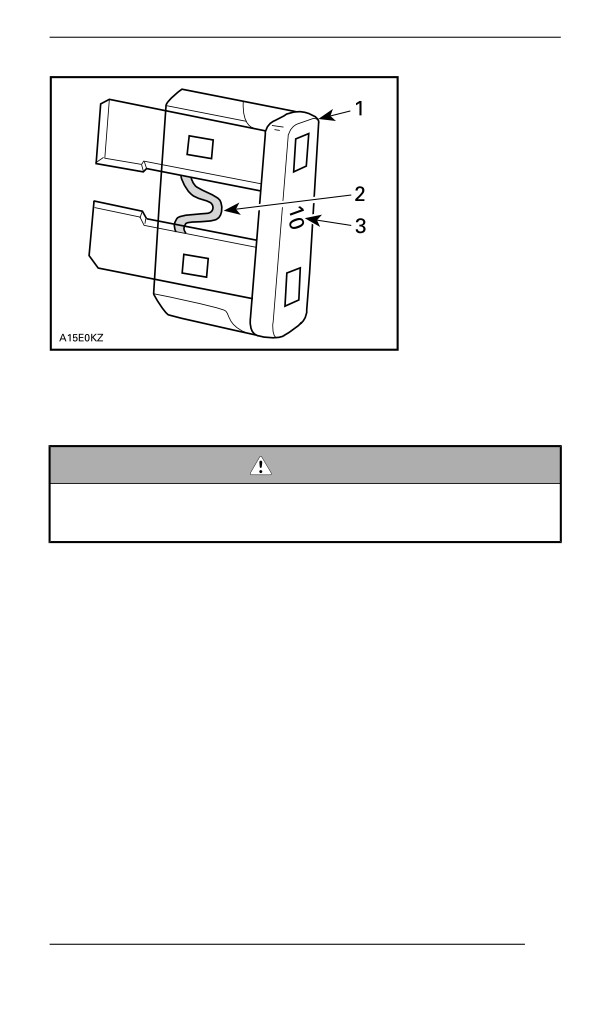
MAINTENANCE PROCEDURES
TYPICAL
1. Fuse
2. Check if melted
3. Ampere rating
WARNING
If fuse burns out repeatedly, source of malfunction should be
determined and corrected before restarting. Visit an authorized
dealer for servicing.
Headliights
Headlights Beam Aiming
Open the storage compartment.
245
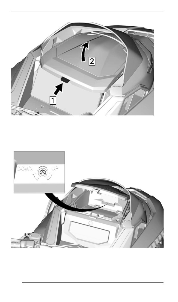
MAINTENANCE PROCEDURES
TYPICAL
Step 1. Push
Step 2. Lift
Turn the adjustment screw to reach desired beam height.
TYPICAL
246
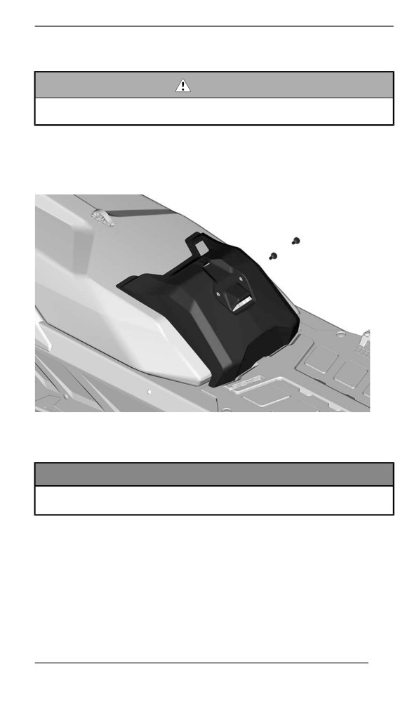
MAINTENANCE PROCEDURES
Battery
WARNING
Never charge or boost the battery while it is installed on the
vehicle.
Removing the Battery
1. Remove the seat.
2. Remove the battery cover.
TYPICAL
3. Disconnect the negative terminal first, then the positive terminal.
NOTICE
Battery BLACK ( – ) cable must always be disconnected first
and connected last.
247
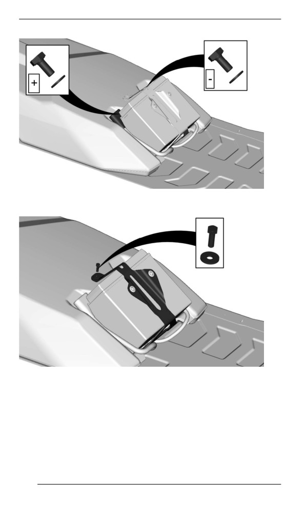
MAINTENANCE PROCEDURES
4. Remove the battery hold down bracket.
5. Remove the battery.
248
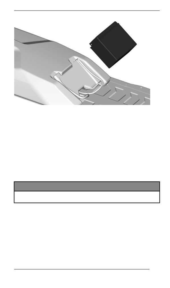
MAINTENANCE PROCEDURES
Cleaning the Battery
Clean battery casing and battery posts using a soft brush and a solu-
tion of baking soda and water.
Remove corrosion from battery cable terminals and battery posts us-
ing a firm wire brush.
Rinse with clear water then dry well.
Charging the Battery
Use any automotive type battery charger. Always refer to the battery
charger manufacturer’s instructions.
Installing the Battery
NOTICE
Battery BLACK ( – ) cable must always be disconnected first
and connected last.
The installation is the reverse of the removal procedure. However, pay
attention to the following details.
249
MAINTENANCE PROCEDURES
TIGHTENING TORQUE
Battery terminals (positive and
10 ± 2 Nm
negative)
(89 ± 18 lbf-in)
5 ± 0.5 Nm
Battery hold down bracket
(44 ± 4 lbf-in)
1.5 ± 0.5 Nm
Battery cover retaining screws
(13 ± 4 lbf-in)
250
VEHICLE CARE
Post-Operatiion Care
Remove snow and ice from rear suspension, track, front suspension,
steering mechanism and skis.
WARNING
Make sure D.E.S.S. key is removed from D.E.S.S. post before
standing in front the vehicle, getting close to the track or rear
suspension components.
Always cover your snowmobile when leaving it outside overnight or
during extended periods of inactivity. This will protect it from frost and
snow as well as help retain its appearance.
Vehicle Cleaning and Protectiion
Wash snowmobile using water mixed with a mild detergent.
Use only microfiber cloths or an equivalent.
NOTICE
Never use a high pressure washer to clean the vehicle. Use low
pressure only, like a garden hose.
Non Compatible Cleaning Products
Material Type
Non-Compatible Cleaning Products
BRAKE AND PARTS CLEANER
All plastics, vinyls,
OR
painted steel and
ANY PETROLEUM BASE CLEANING
aluminium
PRODUCTS
Compatible Cleaning Products
Material Type
Cleaning Product
All plastics, vinyls,
Automotive type soap with water
painted steel and
XPS Spray Cleaner and Polish
aluminium.
XPS All Purpose Cleaner
For more information and products, Visit the XPS Products website at
251
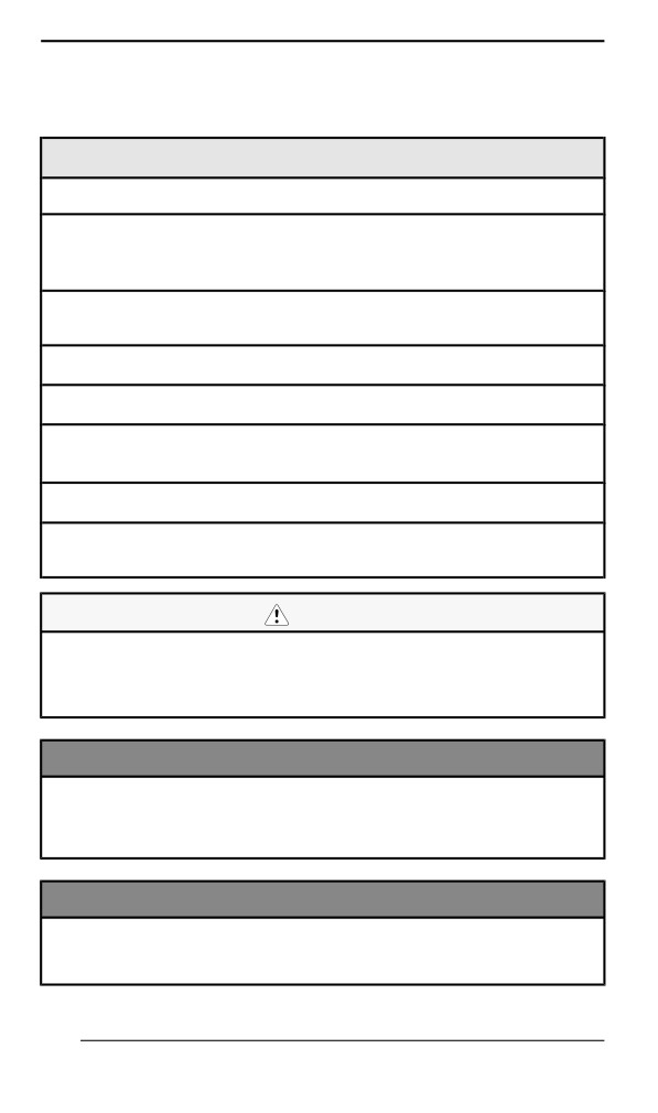
STORAGE
During summer, or when a snowmobile is not in use for more than
three months, proper storage is necessary.
Storage
Clean the vehicle
Add fuel stabilizer to fuel following the product manufacturer
recommendations.
Run the engine after adding the product to the fuel
Lubricate engine. Refer to Engine Storage Procedure in this
section.
Lubricate brake lever pivot
Lubricate rear suspension
Charge battery monthly to keep it fully charged during storage (if
equipped)
Block muffler outlet with rags
Lift rear of vehicle until track is clear of the ground. Do not release
track tension
CAUTION
Use appropriate lifting device or have assistance to share lifting
stress. If a lifting device is not used, use proper lifting techni-
ques, notably using your legs force. Do not attempt to lift the
rear of vehicle if it is above your limits.
NOTICE
The snowmobile has to be stored in a cool and dry place and
covered with an opaque but ventilated tarpaulin. This will pre-
vent sun rays and grime from affecting plastic components and
vehicle finish.
NOTICE
Fuel stabilizer should be added prior to engine lubrication to
prevent the loss of the chemical properties of fuel and protect
the fuel system against varnish deposits.
252
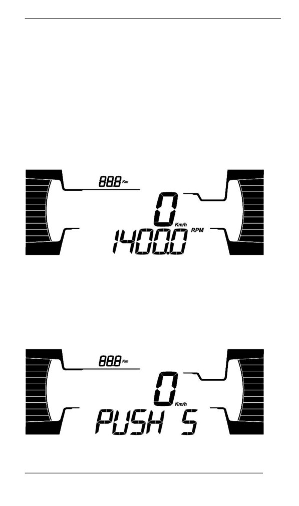
STORAGE
Engine Storage Procedure
The engine has to be properly lubricated at storage for internal parts
protection.
E-TEC Engine - 4.5” and 7.2” Digital Display
Follow these simple steps.
To engage the procedure, do the following:
1. Place the vehicle in a well ventilated area.
2. Start the engine and let it run at idle speed until it reaches its oper-
ating temperature (watch the coolant temperature on the display or
verify the rear heat exchanger becomes warm).
3. Push the SET (S) button to select odometer mode.
TYPICAL
NOTE:
The storage mode does not function in other modes (trip A, trip B and
hr trip).
4. Repeatedly depress the HI/LOW beam switch rapidly, then, while
doing this, press and hold the SET button until PUSH "S" ap-
pears on the display.
TYPICAL
253
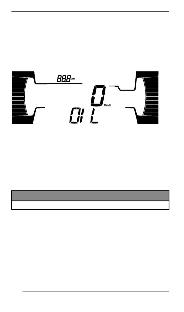
STORAGE
5. Release all buttons when gauge displays PUSH (S) appears.
6. Again, press and hold the SET (S) button for 2 - 3 seconds.
NOTE:
The gauge will display OIL when the storage procedure is initiated.
7. When gauge displays OIL, release button and wait for the lubrica-
tion function to end.
TYPICAL
Do not touch anything during engine lubrication cycle.
The engine lubrication function takes approximately 1 minute. Dur-
ing this time the engine RPM will increase slightly to approximately
1600 RPM and the oil pump will "oil flood" the engine.
At the end of engine lubrication procedure, the ECM will turn the
engine off.
Remove tether cord cap from engine cut-off switch.
NOTICE
Do not start the engine during storage period.
E-TEC Engine - 10.25” Color Touchscreen Display
To engage the procedure, do the following:
1. Place the vehicle in a well ventilated area near storage area.
2. Start the engine and let it run at idle speed until it reaches its oper-
ating temperature (watch the coolant temperature on the display or
verify the rear heat exchanger becomes warm).
3. Go to
”Vehicle Settings”, select
“Vehicle Health” and then
“Procedures”.
4. Press and hold on “Start Summerization” and follow the steps on
screen.
254
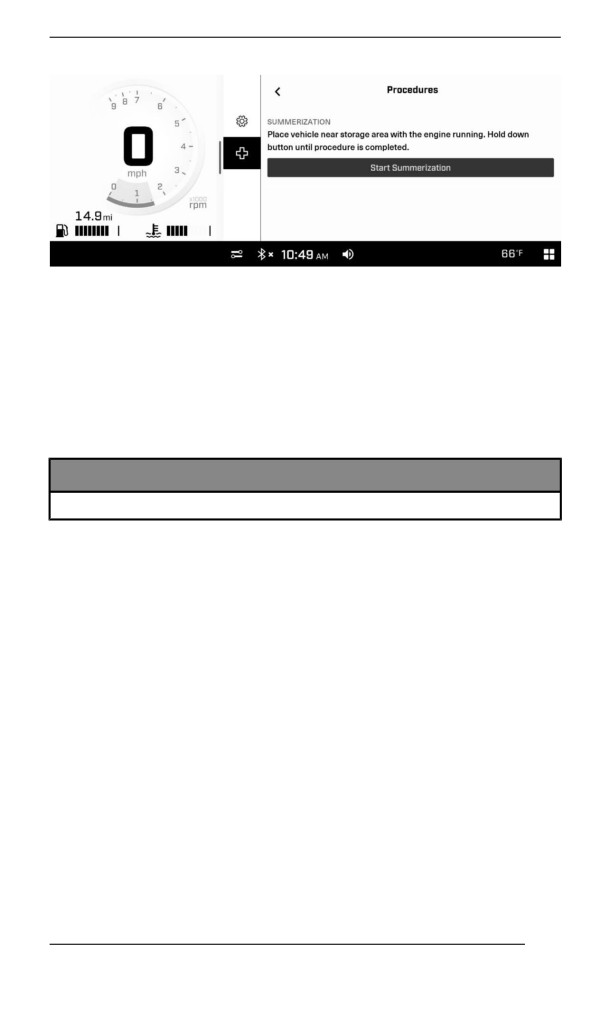
STORAGE
Do not touch anything during engine lubrication cycle.
The engine lubrication function takes approximately 1 minute. Dur-
ing this time the engine RPM will increase between 1500 and 2000
RPM and the oil pump will "oil flood" the engine.
At the end of engine lubrication procedure, the ECM will turn the
engine off.
Remove tether cord cap from engine cut-off switch.
NOTICE
Do not start the engine during storage period.
255
PRESEASON PREPARATION
Proper vehicle preparation is necessary when a vehicle has not been
used for more than three months.
Using the maintenance schedule, perform the items titled EVERY
YEAR AT PRESEASON.
Visit your authorized BRP snowmobile dealer for more information.
256
MAINTENANCE RECORDS
Send photocopy of maintenance record to BRP if needed.
Pre-delivery
Serial
Signature/Print:
number:
Mileage /
km:
Hours:
Date:
Dealer
no:
Notes:
Refer to vehicle Pre-Delivery Bulletin for detailed installation
procedures
257
MAINTENANCE RECORDS
First inspection
Mileage /
Signature/Print:
km:
Hours:
Date:
Dealer
no:
Notes:
For maintenance schedule refer to Maintenance Information
section of this operator's guide
Service
Mileage /
Signature/Print:
km:
Hours:
Date:
Dealer
no:
Notes:
For maintenance schedule refer to Maintenance Information
section of this operator's guide
258
MAINTENANCE RECORDS
Service
Mileage /
Signature/Print:
km:
Hours:
Date:
Dealer
no:
Notes:
For maintenance schedule refer to Maintenance Information
section of this operator's guide
Service
Mileage /
Signature/Print:
km:
Hours:
Date:
Dealer
no:
Notes:
For maintenance schedule refer to Maintenance Information
section of this operator's guide
259
MAINTENANCE RECORDS
Service
Mileage /
Signature/Print:
km:
Hours:
Date:
Dealer
no:
Notes:
For maintenance schedule refer to Maintenance Information
section of this operator's guide
Service
Mileage /
Signature/Print:
km:
Hours:
Date:
Dealer
no:
Notes:
For maintenance schedule refer to Maintenance Information
section of this operator's guide
260
MAINTENANCE RECORDS
Service
Mileage /
Signature/Print:
km:
Hours:
Date:
Dealer
no:
Notes:
For maintenance schedule refer to Maintenance Information
section of this operator's guide
Service
Mileage /
Signature/Print:
km:
Hours:
Date:
Dealer
no:
Notes:
For maintenance schedule refer to Maintenance Information
section of this operator's guide
261
MAINTENANCE RECORDS
Service
Mileage /
Signature/Print:
km:
Hours:
Date:
Dealer
no:
Notes:
For maintenance schedule refer to Maintenance Information
section of this operator's guide
Service
Mileage /
Signature/Print:
km:
Hours:
Date:
Dealer
no:
Notes:
For maintenance schedule refer to Maintenance Information
section of this operator's guide
262
MAINTENANCE RECORDS
Service
Mileage /
Signature/Print:
km:
Hours:
Date:
Dealer
no:
Notes:
For maintenance schedule refer to Maintenance Information
section of this operator's guide
Service
Mileage /
Signature/Print:
km:
Hours:
Date:
Dealer
no:
Notes:
For maintenance schedule refer to Maintenance Information
section of this operator's guide
263
MAINTENANCE RECORDS
Service
Mileage /
Signature/Print:
km:
Hours:
Date:
Dealer
no:
Notes:
For maintenance schedule refer to Maintenance Information
section of this operator's guide
Service
Mileage /
Signature/Print:
km:
Hours:
Date:
Dealer
no:
Notes:
For maintenance schedule refer to Maintenance Information
section of this operator's guide
264
TECHNICAL
INFORMATION
265
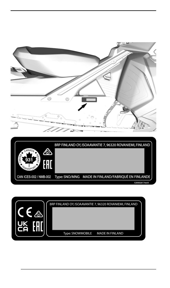
VEHICLE IDENTIFICATION
Vehiiclle Descriiptiion Decal
Vehicle description decal is located on right hand side of tunnel.
FOR NORTH AMERICAN MARKET
520002459
FOR EUROPEAN MARKET
266
VEHICLE IDENTIFICATION
Identificatiion Numbers
The main components of your snowmobile (engine and frame) are
identified by different identification numbers. It may sometimes be-
come necessary to locate these numbers for warranty purposes or to
trace your snowmobile in the event of loss. These numbers are re-
quired by the authorized BRP snowmobile dealer to complete war-
ranty claims properly. We strongly recommend that you take note of
all the identification numbers on your snowmobile and supply them to
your insurance company.
Vehicle Identification Number (VIN)
VIN is scribed on vehicle description decal. See above. It is also en-
graved on tunnel near vehicle description decal.
Model number and model year are part of the information found in the
VIN. See illustration.
2BP
S
LSAB
9
A
V
000001
2BP = Canada
Serial
Model number
YH2 = Finland
number
Factory
S = Ski-Doo
V = Valcourt
L = Lynx
R = Rovaniemi
Numeric or
Alphabetic
Model year: P = 2023
R= 2024
267
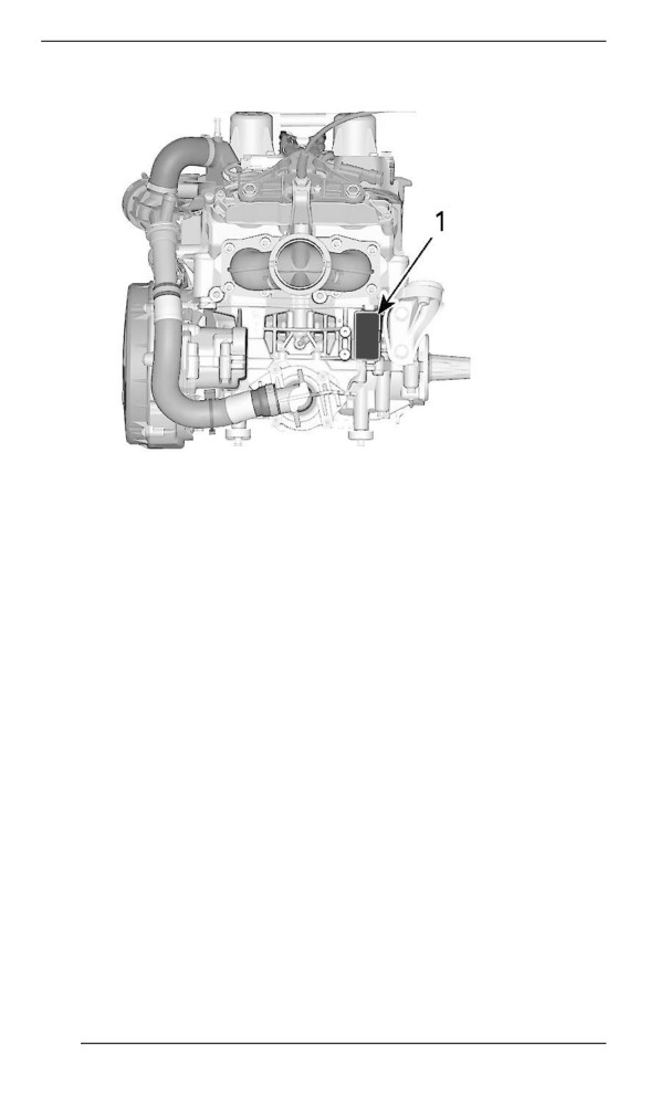
VEHICLE IDENTIFICATION
Engine Identification Number Location
1. Engine identification number
268
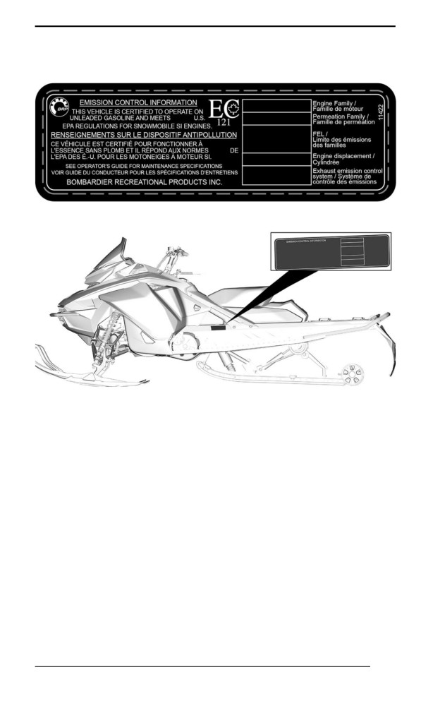
COMPLIANCE LABELS
EPA Complliance Label
EPA COMPLIANCE LABEL
TYPICAL
269
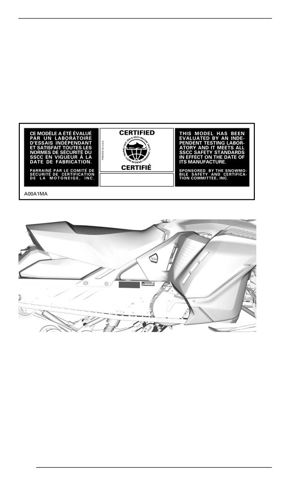
COMPLIANCE LABELS
SSCC Labell
Safety standards for snowmobiles have been adopted by the Snow-
mobile Safety and Certification Committee (SSCC) of which BRP is a
proud participating member. Assurance that your snowmobile meets
these standards is easily checked by locating the Certification Label
on a right vertical portion of the vehicle.
The following label shows that an independent testing laboratory has
verified compliance with the SSCC safety standards.
SSCC LABEL
TYPICAL
270
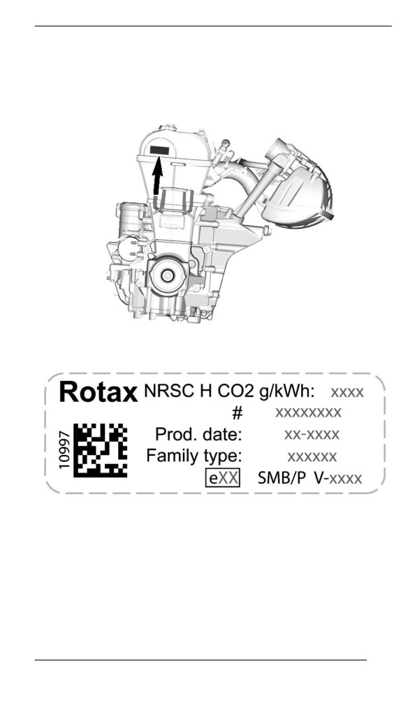
COMPLIANCE LABELS
Regulation (EU) 2016/1628 appliicable for
Non-Road Mobille Machiineriies
Vehicles who comply to Regulation (EU) 2016/1628 (NRMM) are iden-
tified on the engine valve cover.
TYPICAL
NRMM IDENTIFICATION ON ENGINE
271
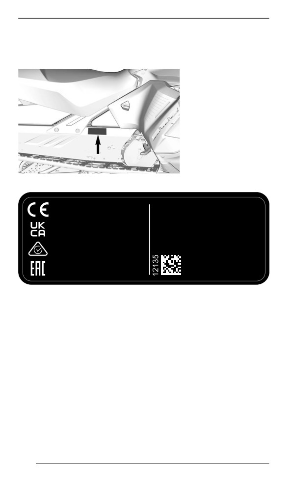
COMPLIANCE LABELS
Depending on your particular vehicle configuration, an additional
NRMM identification decal may be installed on the tunnel, near the
gearbox.
TYPICAL - ON RH SIDE OF TUNNEL
Bombardier Recreational
Products Inc.
565 de la Montagne,
Valcourt,QC, Canada
J0E 2L0
BRP-Rotax GmbH Co. KG
Rotaxstrasse 1
Gunskirchen, A-4623
Austria
Rotax
NRMM IDENTIFICATION ON VEHICLE
272

NOISE EMISSION AND VIBRATION VALUES
MODEL
600R E-TEC
850 E-TEC
NOISE EMISSION AND VIBRATION VALUES1
Sound
102 dB
100 dB
power
(Uncertainty
(Uncertainty
level (LWA)
(Kwa) 3 dB)
(Kwa) 3 dB)
Noise
Sound
90 dB
86 dB
pressure
(Uncertainty
(Uncertainty
(LpA)
(KpA) 3 dB)
(KpA) 3 dB)
Hand-arm
4.3 m/s2
<2.5 m/s2
system
Vibra
tion
Whole
body at
<0.5 m/s2
<0.5 m/s2
seat
1: Noise emission and Vibration values are measured
in accordance with Annexes A and B of ISMA 1
regulation on a snow covered or grass surface in
neutral or without belt.
273
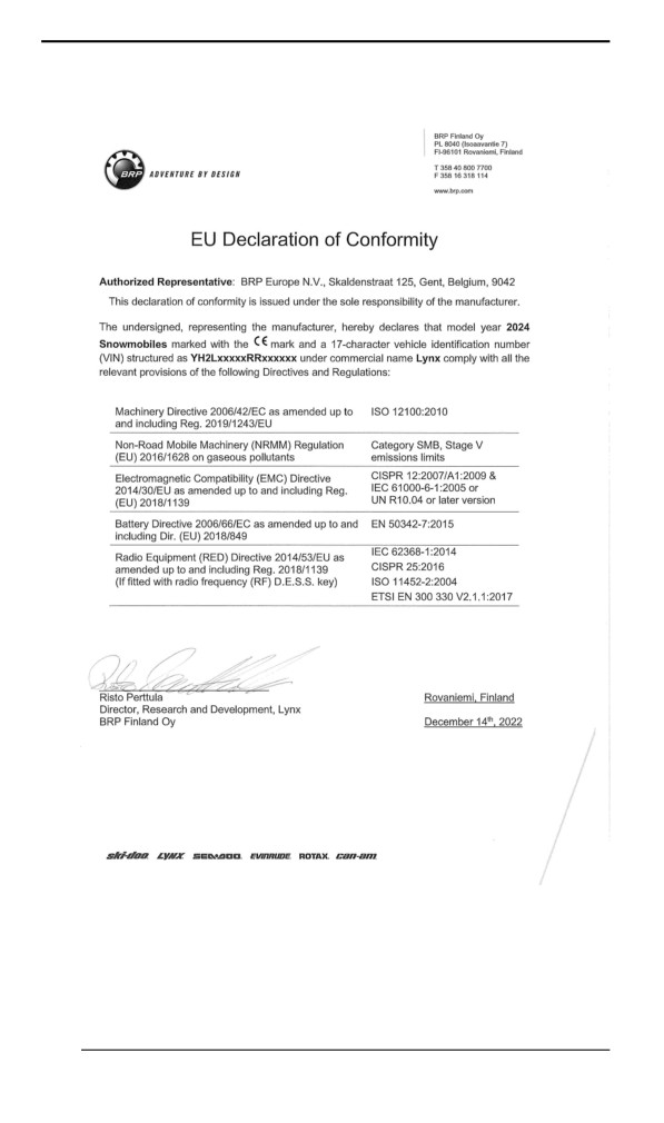
EU DECLARATION OF CONFORMITY
274
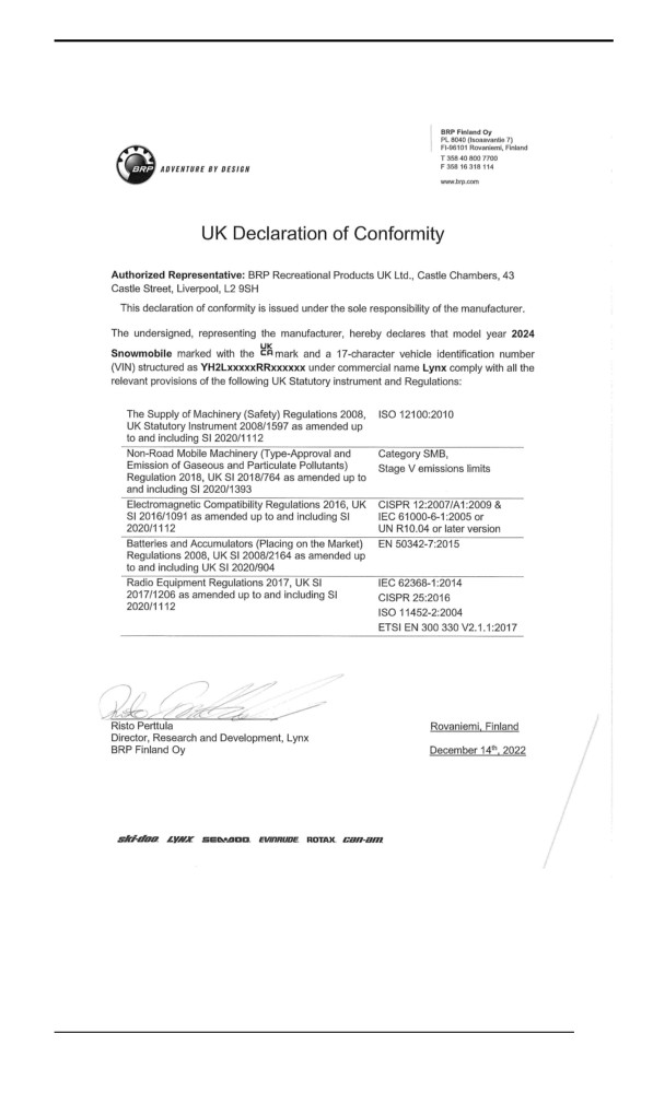
UK DECLARATION OF CONFORMITY
275
EAC DECLARATION OF CONFORMITY
Left blank for Eurasian Conformity
mark where applicable
276
EPA CERTIFIED ENGINES
Engine Emiissiions Information
Manufacturer''s Responsibility
Snowmobile manufacturers of snowmobile engines need to determine
the exhaust emission levels for each engine horsepower family and
certify these engines with the United States of America Environmental
Protection Agency (EPA). An emissions control information label,
showing emission levels and engine specifications, must be placed on
each vehicle at the time of manufacture.
Dealer''s Responsibility
When performing service on a certified BRP snowmobiles that carry
an emissions control information label, adjustments must be kept with-
in published factory specifications.
Replacement or repair of any emission related component must be
executed in a manner that maintains emission levels within the pre-
scribed certification standards.
Dealers are not to modify the engine in any manner that would alter
the horsepower or allow emission levels to exceed their predeter-
mined factory specifications.
Exceptions include manufacturer's prescribed changes, such as alti-
tude adjustments for example.
Owner’s Responsibility
The owner / operator is required to have engine maintenance per-
formed to maintain emission levels within prescribed certification
standards.
The owner / operator is not to, and should not allow anyone to modify
the engine in any manner that would alter the horsepower or allow
emissions levels to exceed their predetermined factory specifications.
EPA Emission Regulations
All BRP snowmobiles manufactured by BRP are certified to the EPA
as conforming to the requirements of the regulations for the control of
air pollution from new snowmobile engines. This certification is contin-
gent on certain adjustments being set to factory standards. For this
reason, the factory procedure for servicing the product must be strictly
followed and, whenever practicable, returned to the original intent of
the design.
The responsibilities listed above are general and in no way a complete
listing of the rules and regulations pertaining to the EPA requirements
on exhaust emissions for snowmobile products. For more detailed in-
formation on this subject, you may contact the following locations:
277
EPA CERTIFIED ENGINES
MAIL:
U.S. Environmental Protection Agency
Certification Division
Gasoline Engine Compliance Center
2000 Traverwood Drive
Ann Arbor MI 48105
USA
INTERNET WEB SITE:
278
RADIO FREQUENCY DIGITALLY ENCODED
SECURITY SYSTEM (RF D.E.S.S. KEY)
This device complies with FCC Part 15 and Industry Canada license
exempt RSS standard(s).
Operation is subject to the following two conditions: (1) this device
may not cause interference, and (2) this device must accept any inter-
ference, including interference that may cause undesired operation of
the device.
Changes or modifications not expressly approved by the party respon-
sible for compliance could void the user’s authority to operate the
equipment.
IC Registration Number: 12006A-1001301698
FCC ID: 2ACER-1001301698
We, the party responsible for compliance, declare under our sole re-
sponsibility that the device is in conformity with the provisions of the
following Council Directive: 2014/53/EU. To which this declaration re-
lates is in conformity with the essential requirements and other rele-
vant requirements. The product is in conformity with the following
directives, harmonized standards and regulations:
Radio Equipment Directive
(RED)
2014/53/EU and Harmonized
Standards:
IEC 62368-1:2014, CISPR 25:2016, ISO 11452-2:2004, ETSI EN 300
330 V2.1.1:2017
Radio Equipment Statutory Instrument 2017/1206 and Designated
Standards:
IEC 62368-1:2014, CISPR 25:2016, ISO 11452-2:2004, ETSI EN 300
330 V2.1.1:2017
279