Vauxhall Movano C (2023 year). Manual in english - page 6
 

  Index      Manuals     Vauxhall Movano C (2023 year). Manual in english


Search            copyright infringement  


Content      ..     4      5      6      7     ..


Vauxhall Movano C (2023 year). Manual in english - page 6


162

Vehicle care

Electrical system

Fuses

A defective fuse must be replaced by

a workshop.

Vehicle tools

Tools

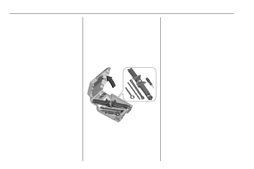
The tools are located in the storage

box underneath the front passenger

seat.
Underseat storage 

3

 37.

Vehicles with spare wheel

The box includes:

● Extended socket
● Wheel bar
● Jack
● Wheelbrace

● Screwdriver (handle and bits)
● Towing eye
● Depending on version a kit for

storing a damaged alloy wheel

rim

Vehicles without spare wheel

The box contains the tools and the

tyre repair kit.
Tyre repair kit 

3

 167.

Vehicle care

163

Wheels and tyres

Tyre condition, wheel condition

Drive over edges slowly and at right

angles if possible. Driving over sharp

edges can cause tyre and wheel

damage. Do not trap tyres on the kerb

when parking.
Regularly check the wheels for

damage. Seek the assistance of a

workshop in the event of damage or

unusual wear.

Winter tyres

Winter tyres improve driving safety at

temperatures below 7 °C and should

therefore be fitted on all wheels.
In accordance with country-specific

regulations, affix the speed sticker in

the driver's field of view, if the tyre

speed code is below the maximum

speed of the vehicle.

Tyre designations

E.g. 225/55 R 18 98 V
225 : tyre width, mm

55 : cross-section ratio (tyre height

to tyre width), %

R

: belt type: Radial

RF : type: RunFlat

18 : wheel diameter, inches

98 : load index e.g. 98 is equivalent

to 750 kg

V

: speed code letter

Speed code letter:
Q : up to 100 mph

S : up to 112 mph

T : up to 118 mph

H : up to 130 mph

V : up to 150 mph

W : up to 168 mph
Choose a tyre appropriate for the

maximum speed of your vehicle.

Refer to the EEC Certificate of

Conformity provided with your vehicle

or other national registration

documents. Optional equipment

could reduce the maximum speed of

the vehicle.

Directional tyres

Directional tyres should be mounted

so that they rotate in the correct

direction. The proper rotation

direction is indicated by a symbol

(e.g. an arrow) on the sidewall.

Tyre pressure

Check the pressure of cold tyres at

least every 14 days and before any

long journey. Do not forget the spare

wheel. This also applies to vehicles

with tyre pressure monitoring system.

164

Vehicle care

The tyre pressure information label

on the left door frame indicates the

original equipment tyres and the

correspondent tyre pressures.
The tyre pressure data refers to cold

tyres. It applies to summer and winter

tyres.
Always inflate the spare tyre to the

pressure specified for full load.
Incorrect tyre pressures will impair

safety, vehicle handling, comfort and

fuel economy and will increase tyre

wear.
For the tyres approved for your

vehicle, refer to the EEC Certificate of

Conformity provided with your vehicle

or other national registration

documents.
The driver is responsible for correct

adjustment of tyre pressure.

9

Warning

If the pressure is too low, this can

result in considerable tyre warm-

up and internal damage, leading to

tread separation and even to tyre

blow-out at high speeds.

Temperature dependency

The tyre pressure depends on the

temperature of the tyre. During

driving, tyre temperature and

pressure increase. Tyre pressure

values provided on the tyre

information label and tyre pressure

chart are valid for cold tyres, which

means at 20 °C.
The pressure increases by nearly

1.5 psi for a 10 °C temperature

increase. This must be considered

when warm tyres are checked.

Tyre pressure monitoring

system

The tyre pressure monitoring system

checks the pressure of all four tyres

once a minute when vehicle speed

exceeds a certain limit.

Caution

Tyre pressure monitoring system

warns only about low tyre pressure

condition and does not replace

regular tyre maintenance by the

driver.

All wheels must be equipped with

pressure sensors and the tyres must

have the prescribed pressure.

Notice

In countries where the tyre pressure

monitoring system is legally

required, the use of wheels without

pressure sensors will invalidate the

vehicle operating permit.

If a tyre loses pressure the control

indicator 

w

 illuminates and a warning

chime is given. Depending on

version, a warning message is

displayed in the Driver Information

Centre.
Depending on version and if only one

tyre is affected, the tyre can be

identified by the system and is

displayed by the symbol and the

message.

Vehicle care

165

The system considers the tyre

temperature for the warnings.
Temperature dependency 

3

 163.

If the control indicator 

w

 illuminates

continously the tyre pressure has to

be adjusted 

3

 58.

In this case reduce speed, avoid

sharp cornering and strong braking.

Stop at next safe opportunity, check

tyre pressure to the prescribed

pressure.
After inflating, some driving may be

required to update the tyre pressure

values in the Driver Information

Centre. It might take about

20 minutes until 

w

 extinguishes.

If the failure continues to be

displayed, contact a workshop. The

system is inoperable when ABS or

ESC has a malfunction or a

temporary spare wheel is used. Once

the road tyre has been refitted, check

the tyre pressure with cold tyres and

initialise the system.
Only mount wheels with pressure

sensors, otherwise the tyre pressure

will not be displayed and 

w

illuminates continuously.

A spare wheel or temporary spare

wheel is not equipped with pressure

sensors. The tyre pressure

monitoring system is not operational

for these tyres. Control indicator 

w

illuminates. For the further three

tyres, the system remains

operational.
The use of commercially-available

liquid tyre repair kits can impair the

function of the system. Factory-

approved repair kits can be used.
Operating electronic devices or being

close to facilities using similar wave

frequencies could disrupt the tyre

pressure monitoring system.
Each time the tyres are replaced, tyre

pressure monitoring system sensors

must be dismounted and serviced.

Auto learn function

After changing wheels or wheel

positions the vehicle must be

stationary for approx. 20 minutes,

before the system recalculates. The

following relearn process takes up to

ten minutes of driving in a speed

range of 25 to 60 mph. Avoid to drive

outside of this range for a longer time.

If possible, use a country road or

similar which allows continuous

driving.
Ensure the tyre loading status is set

according to the selected pressure

3

 60.

If problems occur during the relearn

process, a failure message is

displayed in the Driver Information

Centre. 

w

 will flash for 75 seconds

and then illuminates continuously.
If this happens, repeat learning

process. Keep your vehicle stationary

for approx. 20 minutes and then drive

again for ten minutes as described

above.

Tread depth

Check tread depth at regular

intervals.
For safety reasons, it is

recommended that the tread depth of

the tyres on one axle should not vary

by more than 2 mm.

166

Vehicle care

The legally permissible minimum

tread depth (1.6 mm) has been

reached when the tread has worn

down as far as one of the tread wear

indicators (TWI). Their position is

indicated by markings on the

sidewall.
If there is more wear at the front than

the rear, swap round front wheels and

rear wheels periodically. Ensure that

the direction of rotation of the wheels

remains the same.
Tyres age, even if they are not used.

We recommend tyre replacement

every six years.

Changing tyre and wheel

size

If tyres of a different size than those

fitted at the factory are used, it may be

necessary to reprogramme the

nominal tyre pressure and make

other vehicle modifications.
After converting to a different tyre

size, have the label with tyre

pressures replaced and the tyre

pressure monitoring system

reinitialised 

3

 164.

9

Warning

The use of unsuitable tyres or

wheels may lead to accidents and

will invalidate the vehicle

operating permit.

Wheel covers

Wheel covers and tyres that are

factory approved for the respective

vehicle and comply with all of the

relevant wheel and tyre combination

requirements must be used.

If the wheel covers and tyres used are

not factory approved, the tyres must

not have a rim protection ridge.
Wheel covers must not impair brake

cooling.

9

Warning

Use of unsuitable tyres or wheel

covers could lead to sudden

pressure loss and thereby

accidents.

Vehicles with steel wheel rims: When

using locking wheel nuts, do not

attach wheel covers.

Vehicle care

167

Tyre chains

Tyre chains are only permitted on the

front wheels.
Always use fine mesh chains that add

no more than 9 mm to the tyre tread

and the inboard sides (including chain

lock).

9

Warning

Damage may lead to tyre blowout.

Tyre chains are permitted on tyres of

size 205/70R15, 215/70 R15,

225/70 R15, 215/75 R16 and

225/75 R16.

Temporary spare wheel

The use of tyre chains is not permitted

on the temporary spare wheel.

Tyre repair kit

Minor damage to the tyre tread can be

repaired with the tyre repair kit.
Do not remove foreign bodies from

the tyres.
Tyre damage exceeding 4 mm or that

is at tyre's sidewall cannot be repaired

with the tyre repair kit.

9

Warning

Do not drive faster than 50 mph.
Do not use for a lengthy period.
Steering and handling may be

affected.

In the case of a flat tyre:
Apply the parking brake and engage

first gear or reverse gear.
The tyre repair kit is stored in the tool

box or in one of the front doors.

It includes:

● a quick user guide for the repair

kit

● a cartridge, containing the

sealeant

● a compressor equipped with a

pressure gauge and connectors

● adapters for the inflation of

various components

● a sticker
● a pair of protective gloves

1. filler hose
2. compressor
3. switch with position (off/on): 

J

 / I

168

Vehicle care

4. pressure gauge
5. Cartridge, containing the sealant;

sticker on the top marked with

50 mph to affix after the repairing

on the instrument panel.

6. Hose to check and restore tyre

pressure

Repair the tyre

1. Unscrew the valve cap from the

defective tyre.

2. Screw the filler hose to the tyre

valve.

3. The switch on the compressor

must be set to 

J

.

4. Connect the compressor plug to

the power outlet or cigarette

lighter socket.
To avoid discharging the vehicle

battery, we recommend to use the

tyre repair kit only when

combustion engine is running or

when electric engine is ready.

5. Set the rocker switch on the

compressor to I. The tyre is filled

with sealant.

6. The compressor pressure gauge

briefly indicates up to

600 kPa (6 bar) whilst the sealant

cartridge is emptying (approx.

30 s). Then the pressure starts to

drop.

7. All of the sealant is pumped into

the tyre. Then the tyre is being

inflated.

8. The prescribed tyre pressure

should be obtained within ten

minutes.
When the correct pressure is

obtained, switch off the

compressor.
If the prescribed tyre pressure is

not obtained within ten minutes,

remove the tyre repair kit. Move

the vehicle forwards by about

10 m to distribute the sealing fluid

inside the tyre evenly. Reattach

the tyre repair kit and continue the

filling procedure for 10 minutes. If

the prescribed tyre pressure is still

not obtained, the tyre is too badly

damaged. Seek the assistance of

a workshop.
Do not run the compressor longer

than ten minutes.

9. Detach the tyre repair kit. Store

the tyre repair kit back in the

storage compartment of the door.

10. Remove any excess sealant

using a cloth.

11. Continue driving immediately so

that sealant is evenly distributed

in the tyre. After driving approx.

three miles but no more than ten

minutes, stop and check tyre

pressure. Screw compressor air

hose directly onto tyre valve when

doing this. Fill tyre as described

before. Drain excess tyre

pressure with the button on the air

hose.

Vehicle care

169

If tyre pressure hasn't decreased

under 150 kPa (1.5 bar), set it to

the correct value. Otherwise the

vehicle must not be used. Seek

assistance of a workshop.
Repeat the checking procedure

once more after driving further

6 miles but no more than ten

minutes to check that there is no

more loss of pressure.
If the tyre pressure has fallen

below 150 kPa (1.5 bar), the

vehicle must not be used. Seek

the assistance of a workshop.

Notice

The driving characteristics of the

repaired tyre are severely affected,

therefore have this tyre replaced.
If unusual noise is heard or the

compressor becomes hot, turn

compressor off for at least 30 min.
The built-in safety valve opens at a

pressure of seven bar (102 psi).
Note the expiry date of the kit. After

this date its sealing capability is no

longer guaranteed. Pay attention to

storage information on sealant

bottle.

Replace the used sealant bottle.

Dispose of the bottle as prescribed

by applicable laws.
The compressor and sealant can be

used from approx. -30 °C.

Checking and restoring pressure

1. Unscrew the valve cap from the

tyre.

2. Take out the pressure hose and

connect it to the tyre valve.
The cartridge will be connected to

the compressor and the tyre is

inflated, but no sealant will be

injected.

To deflate the tyre, press the

yellow button located on the

centre of the compressor switch.

3. Detach the tyre repair kit. Store

the tyre repair kit.

Replacing the sealant cartridge

1. Turn the cartridge to be replaced

anti-clockwise and lift it.

2. Insert the new cartridge and turn

it clockwise.

170

Vehicle care

Wheel changing

Make the following preparations and

observe the following information:

● Park the vehicle on a level, firm

and non-skid surface. The front

wheels must be in the straight-

ahead position.

● If necessary, place a chock under

the wheel diagonally opposite the

wheel to be changed.

● Apply the parking brake and

engage first gear, reverse gear or

P.

● If the ground on which the vehicle

is standing is soft, a solid board

(max. 1 cm thick) should be

placed under the jack.

● Take heavy objects out of the

vehicle before jacking up.

● No people or animals may be in

the vehicle when it is jacked-up.

● Never crawl under a jacked-up

vehicle.

● Do not start the vehicle when it is

raised on the jack.

● Before screwing in the wheel

bolts, clean them.

9

Warning

Do not grease wheel bolts.

Tightening torques

The tightening torque for 15 inches

wheels is 160 Nm.
The tightening torque for 16 inches

wheels is 180 Nm.
Use the correct wheel bolts for the

respective wheels.

Spare wheel

The spare wheel can be classified as

a temporary spare wheel depending

on the size compared to the other

mounted wheels and country

regulations. In this case a permissible

maximum speed applies, even

though no label at the spare wheel

indicates this.
If there is a label on the spare wheel,

the permissible speed still depends

on the country regulations.
Only mount one temporary spare

wheel. Take curves slowly. Do not

use for a long period of time.

Caution

The use of a spare wheel that is

smaller than the other wheels or in

combination with winter tyres

could affect driveability. Have the

defective tyre replaced as soon as

possible.

The spare wheel is located

underneath the vehicle.
The vehicle tools extended socket,

wheelbrace and wheel bar are

needed to get access.
If equipped with alloy wheel rims, the

provided kit is also needed. 

3

 162

1. Lift the rear of the vehicle to

facilitate the access.

Vehicle care

171

2. Assemble the extended socket,

wheelbrace and wheel bar

correctly to a wrench and install it

on the retaining bolt.
Turn the wrench anti-clockwise to

lower the spare wheel.
Continue turning anti-clockwise

until the resistance point,

indicated by the stiffening at

turning or a click from the clutch

present in the device.

3. Unwind the whole cable of the

spare wheel lifting device

4. Unscrew the retaining knob.

Remove the support by tilting one

side.

5. Remove the spare wheel.
6. Change the wheel.

7. If the damaged wheel has an alloy

rim, follow these steps:

● Position the support (3)

inside the bracket of the tool

kit (2).

● Position the bracket (2) on

the inside of the alloy wheel

rim.

● Tighten the retaining knob (1)

on the bracket (2).

● Tighten the three special

screws (4) from under the

damaged wheel to the nuts of

the bracket (4), using the

allen spanner.

172

Vehicle care

8. If the damaged wheel has a steel

rim, follow these steps:

● Position the support on the

inside of the steel wheel rim

and reattach it by tilting in.

● Tighten the retaining knob.

9. Position the wrench on the screw

of the support and turn clockwise

until the wheel is lifted up

completely.
Check the correct position of the

wheel under the platform.

10. Put the tools back in the storage.

Only mount one temporary spare

wheel. The permissible maximum

speed on the label on the temporary

spare wheel is only valid for the

factory-fitted tyre size.

Fitting the spare wheel

Make the following preparations and

observe the following information:

● Park the vehicle on a level, firm

and non-skid surface. The front

wheels must be in the straight-

ahead position.

● If necessary, place a chock under

the wheel diagonally opposite the

wheel to be changed.

● Apply the parking brake and

engage first gear, reverse gear or

P.

● Remove the spare wheel.
● Never change more than one

wheel at once.

● Use the jack only to change

wheels in case of puncture, not

for seasonal winter or summer

tyre change.

● The jack is maintenance-free.
● If the ground on which the vehicle

is standing is soft, a solid board

(max. 1 cm thick) should be

placed under the jack.

● Take heavy objects out of the

vehicle before jacking up.

Vehicle care

173

● No people or animals may be in

the vehicle when it is jacked-up.

● Never crawl under a jacked-up

vehicle.

● Do not start the vehicle when it is

raised on the jack.

● Before screwing in the wheel

bolts, clean them.

9

Warning

Do not grease wheel bolts.

1. Steel wheel rims with cover: Pull

off the wheel cover.
Alloy wheel rims: Disengage

wheel bolt caps with the wheel

bolt cover remover.

2. Attach the wheel wrench and

loosen each wheel bolt by half a

turn.
The wheels might be protected by

locking wheel nuts. To loosen

these specific nuts first attach the

adapter onto the head of the nut

before installing the wheel

wrench. The adapter is located in

the tool box.

3

 162

3. Ensure the jack is correctly

positioned under the relevant

vehicle jacking point near the front

wheel.

174

Vehicle care

4. Ensure the jack is correctly

positioned under the relevant

vehicle jacking point near the rear

wheel.

5. Ensure the notch of the jack fits in

the intended hole.

Set the jack to the necessary

height. Position it directly below

the jacking point in a manner that

prevents it from slipping.

With the jack correctly aligned

rotate the wheel wrench until the

wheel is clear of the ground.

6. If equipped with a side step the

jack has to be positioned at 45° to

not interfere with the side step.

7. Unscrew the wheel nuts.
8. Change the wheel.
9. Screw on the wheel nuts.

10. Lower the vehicle and remove the

jack.

11. Install the wheel wrench ensuring

that it is located securely and

tighten each bolt in a crosswise

Vehicle care

175

sequence. The tightening torque

is 160 Nm for 15 inches wheels

and 180 Nm for 16 inches wheels.

12. Align the valve hole in the wheel

cover with the tyre valve before

installing.
Install the wheel nut caps.

13. Store the replaced wheel, the

vehicle tools 

3

 162 and the

adapter for the locking wheel nuts.

14. Check the tyre pressure of the

installed tyre and the wheel nut

torque as soon as possible.

Jump starting

Do not start with quick charger.
A vehicle with a discharged vehicle

battery can be started using jump

leads and the vehicle battery of

another vehicle.

Caution

Never jump start another vehicle

with an electric vehicle.

9

Warning

Be extremely careful when starting

with jump leads. Any deviation

from the following instructions can

lead to injuries or damage caused

by battery explosion or damage to

the electrical systems of both

vehicles.

9

Warning

Avoid contact of the vehicle

battery with eyes, skin, fabrics and

painted surfaces. The fluid

contains sulphuric acid which can

cause injuries and damage in the

event of direct contact.

● Never expose the vehicle battery

to naked flames or sparks.

● A discharged vehicle battery can

already freeze at a temperature

of 0 °C. Defrost the frozen vehicle

battery before connecting jump

leads.

● Wear eye protection and

protective clothing when

handling a vehicle battery.

● Use a booster battery with the

same voltage (12 V). Its capacity

(Ah) must not be much less than

that of the discharged vehicle

battery.

● Use jump leads with insulated

terminals and a cross section of

at least 16 mm

2

 (25 mm

2

 for

diesel engines).

176

Vehicle care

● Do not disconnect the discharged

vehicle battery from the vehicle.

● Switch off all unnecessary

electrical consumers.

● Do not lean over the vehicle

battery during jump starting.

● Do not allow the terminals of one

lead to touch those of the other

lead.

● The vehicles must not come into

contact with each other during

the jump starting process.

● Apply the parking brake,

transmission in neutral.

Open the positive terminal protection

caps of both vehicle batteries.
Lead connection order:

1. Connect the red lead to the

positive terminal of the booster

battery.

2. Connect the other end of the red

lead to the positive terminal of the

discharged vehicle battery.

3. Connect the black lead to the

negative terminal of the booster

battery.

4. Connect the other end of the black

lead to a vehicle grounding point

of your vehicle in the engine

compartment.

Route the leads so that they cannot

catch on rotating parts in the engine

compartment.
To start the engine:

1. Start the engine of the vehicle

providing the jump.

2. After five minutes, start the other

engine. Start attempts should be

made for no longer than 15 s at an

interval of one minute.

3. Allow both engines to idle for

approx. three minutes with the

leads connected.

4. Switch on electrical consumers

e.g. headlights, seat heating of

the vehicle receiving the jump

start.

5. Reverse above sequence exactly

when removing leads.

Vehicle care

177

Towing

Towing the vehicle

Release the cap carefully with a flat

tool.
The towing eye is stored with the

vehicle tools 

3

 162.

Screw in the towing eye as far as it will

go until it stops in a horizontal

position.
Attach a tow bar to the towing eye.
The towing eye must only be used for

towing and not for recovering the

vehicle.
Switch on ignition to release steering

wheel lock and to permit operation of

brake lights, horn and windscreen

wiper.

Caution

Deactivate the driver assistance

systems like active emergency

braking 

3

 114, otherwise the

vehicle may automatically brake

during towing.

Set the selector lever to neutral or

select neutral N.
Release the parking brake.

Caution

Drive slowly. Do not drive jerkily.

Excessive tractive force can

damage the vehicle.

When the engine is not running,

considerably more force is needed to

brake and steer.
To prevent the entry of exhaust gases

from the towing vehicle, switch on the

air recirculation and close the

windows.

178

Vehicle care

Transport an electric vehicle on a

platform or tow it with the front wheels

lifted.
Seek the assistance of a workshop.
After towing, unscrew the towing eye.
Insert cap with the flange into the

recess and fix cap by pushing.

Towing another vehicle

Attach a tow bar to the fixed towing

eye.
The towing eye must only be used for

towing and not for recovering a

vehicle.

Caution

Drive slowly. Do not drive jerkily.

Excessive tractive force can

damage the vehicle.

Appearance care

Exterior care

Locks

The locks are lubricated at the factory

using a high quality lock cylinder

grease. Use a de-icing agent only

when absolutely necessary, as this

has a degreasing effect and impairs

lock function. After using a de-icing

agent, have the locks regreased by a

workshop.

Washing

The paintwork of the vehicle is

exposed to environmental influences.
Bird droppings, dead insects, resin,

pollen and the like should be cleaned

off immediately, as they contain

aggressive constituents which can

cause paint damage.
If using a vehicle wash, comply with

the vehicle wash manufacturer's

instructions. The windscreen wiper

and rear window wiper must be

Vehicle care

179

switched off. Remove antenna and

external accessories such as roof

racks etc.
If washing the vehicle by hand, make

sure that the insides of the wheel

housings are also thoroughly rinsed

out.
Clean edges and folds on opened

doors and the bonnet as well as the

areas they cover.
Clean bright metal mouldings with a

cleaning solution approved for

aluminium to avoid damages.

Caution

Always use a cleaning agent with

a pH value of 4 to 9.
Do not use cleaning agents on hot

surfaces.

Do not clean the engine compartment

with a steam-jet or high-pressure jet

cleaner.
Thoroughly rinse and leather-off the

vehicle. Rinse leather frequently. Use

separate leathers for painted and

glass surfaces: remnants of wax on

the windows will impair vision.

Have the door hinges of all doors

greased by a workshop.

Exterior lights

Headlight and other light covers are

made of plastic. Do not use any

abrasive or caustic agents, do not use

an ice scraper, and do not clean them

dry.

Polishing and waxing

Polishing is necessary only if the paint

has become dull or if solid deposits

have become attached to it.
Plastic body parts must not be treated

with wax or polishing agents.

Windows and wiper blades

Switch off wipers before handling in

their areas.
Use a soft lint-free cloth or chamois

leather together with window cleaner

and insect remover.
When cleaning the rear window from

inside, always wipe in parallel to the

heating element to prevent damage.

For mechanical removal of ice, use a

sharp-edged ice scraper. Press the

scraper firmly against the glass so

that no dirt can get under it and

scratch the glass.
Clean smearing wiper blades with a

soft cloth and window cleaner. Also

make sure to remove any residues

such as wax, insect residues and

similar from the window.
Ice residues, pollution and continuous

wiping on dry windows will damage or

even destroy the wiper blades.

Wheels and tyres

Do not use high-pressure jet

cleaners.
Clean rims with a pH-neutral wheel

cleaner.
Rims are painted and can be treated

with the same agents as the body.

Paintwork damage

Rectify minor paintwork damage with

a touch-up pen before rust forms.

Have more extensive damage or rust

areas repaired by a workshop.

180

Vehicle care

Underbody

Some areas of the vehicle underbody

have a PVC undercoating while other

critical areas have a durable

protective wax coating.
After the underbody is washed, check

the underbody and have it waxed if

necessary.
Bitumen / rubber materials could

damage the PVC coating. Have

underbody work carried out by a

workshop.
Before and after winter, wash the

underbody and have the protective

wax coating checked.

Towing equipment

Do not clean the coupling ball bar with

a steam-jet or high-pressure jet

cleaner.

Interior care

Interior and upholstery

Only clean the vehicle interior,

including the instrument panel fascia

and panelling, with a dry cloth or

interior cleaner.
The Driver Information Centre and

the displays should only be cleaned

using a soft damp cloth. If necessary

use a weak soap solution.
Clean fabric upholstery with a

vacuum cleaner and brush. Remove

stains with an upholstery cleaner.
Clothing fabrics may not be

colourfast. This could cause visible

discolourations, especially on light-

coloured upholstery. Removable

stains and discolourations should be

cleaned as soon as possible.
Clean seat belts with lukewarm water

or interior cleaner.

Caution

Close Velcro fasteners as open

Velcro fasteners on clothing could

damage seat upholstery.
The same applies to clothing with

sharp-edged objects, like zips or

belts or studded jeans.

Plastic and rubber parts

Plastic and rubber parts can be

cleaned with the same cleaner as

used to clean the body. Use interior

cleaner if necessary. Do not use any

other agent. Avoid solvents and petrol

in particular. Do not use high-

pressure jet cleaners.

Service and maintenance

181

Service and

maintenance

General information ................... 181

Service information .................. 181

Recommended fluids, lubricants

and parts .................................... 183

Recommended fluids and

lubricants ................................ 183

General information

Service information

In order to ensure economical and

safe vehicle operation and to

maintain the value of your vehicle, it

is of vital importance that all

maintenance work is carried out at the

proper intervals as specified.
The detailed, up-to-date service

schedule for your vehicle is available

at the workshop.
Severe operating conditions exist if

one or more of the following

circumstances occur frequently: Cold

starting, stop and go operation, e.g.

for taxis and police vehicles, trailer

operation, mountain driving, driving

on poor and sandy road surfaces,

increased air pollution, presence of

airborne sand and high dust content,

driving at high altitude and large

variations of temperature.
Service display 

3

 52.

182

Service and maintenance

Service intervals

Engine

DW12

DW12

1)

Electric vehicle

Country group 1

32,000 miles / 2 years

2)

12,500 miles / 1 year

12,500 miles / 1 year

Country group 2

12,500 miles / 1 year

12,500 miles / 1 year

12,500 miles / 1 year

1)

Severe operating conditions

2)

Unless otherwise indicated in the service display

Country group 1:

Andorra, Austria, Belgium, Bosnia-Herzegovina, Bulgaria, Croatia, Cyprus, Czech Republic, Estonia, Denmark, Finland,

France, Germany, Greece, Hungary, Iceland, Italy, Latvia, Liechtenstein, Lithuania, Luxembourg, Malta, Monaco,

Netherlands, North Macedonia, Norway, Poland, Portugal, Republic of Ireland, Romania, San Marino, Slovakia, Slovenia,

Spain, Sweden, Switzerland, United Kingdom.
Country group 2:

All other countries which are not listed in country group 1.
Confirmations

Confirmation of service is recorded in the Service and warranty booklet. The date and mileage is completed with the stamp

and signature of the servicing workshop.
Make sure that the Service and warranty booklet is completed correctly as continuous proof of service is essential if any

warranty or goodwill claims are to be met, and is also a benefit when selling the vehicle.

Service and maintenance

183

Recommended fluids,

lubricants and parts

Recommended fluids and

lubricants

Only use products that meet the

recommended specifications.

9

Warning

Operating materials are

hazardous and could be

poisonous. Handle with care. Pay

attention to information given on

the containers.

Engine oil

Engine oil is identified by its quality

and its viscosity. Quality is more

important than viscosity when

selecting which engine oil to use. The

oil quality ensures e.g. engine

cleanliness, wear protection and oil

aging control, whereas viscosity

grade gives information on the oil's

thickness over a temperature range.

The required engine oil quality for the

diesel engine DW12 is B71 2312. The

engine oil viscosity grade is

SAE 0W-30.
For diesel engine with severe

operating conditions the required

engine oil quality is B71 2297 and the

engine oil viscosity grade is

SAE 5W-30.

Topping up engine oil

Caution

In case of any spilled oil, wipe it up

and dispose it properly.

Engine oils of different manufacturers

and brands can be mixed as long as

they comply with the required engine

oil quality and viscosity.

Additional engine oil additives

The use of additional engine oil

additives could cause damage and

invalidate the warranty.

Engine oil viscosity grades

The SAE viscosity grade gives

information of the thickness of the oil.

The recommended viscosity grade is

suitable for high ambient

temperatures.
Multigrade oil is indicated by two

figures, e.g. SAE 5W-30. The first

figure, followed by a W, indicates the

low temperature viscosity and the

second figure the high temperature

viscosity.

Coolant and antifreeze

Use only antifreeze approved for the

vehicle. Consult a workshop.
The system is factory filled with

coolant designed for excellent

corrosion protection and frost

protection down to approx. -28 °C. In

cold regions with very low

temperatures the factory filled coolant

provides frost protection down to

approx. -37 °C. This concentration

should be maintained all year round.

The use of additional coolant

additives that intend to give additional

corrosion protection or seal against

184

Service and maintenance

minor leaks can cause function

problems. Liability for consequences

resulting from the use of additional

coolant additives will be rejected.

Washer fluid

Use only washer fluid approved for

the vehicle to prevent damage of

wiper blades, paintwork, plastic and

rubber parts. Consult a workshop.

Brake fluid

Over time, brake fluid absorbs

moisture which will reduce braking

effectiveness. The brake fluid should

therefore be replaced at the specified

interval.
Use only brake fluid approved for the

vehicle. Consult a workshop.

AdBlue

Only use AdBlue to reduce the

nitrogen oxides in the exhaust

emission 

3

 96.

Technical data

185

Technical data

Vehicle identification .................. 185

Vehicle identification number . . 185

Identification plate ................... 186

Engine identification ................ 186

Vehicle data ............................... 187

Vehicle dimensions ................. 187

Capacities ................................ 187

Vehicle identification

Vehicle identification

number

The vehicle identification number is

embossed on the instrument panel,

visible through the windscreen.

The vehicle identification number is

also displayed behind a removable

plastic cover. Unclip the cover using

a flat blade screwdriver to access.

186

Technical data

Identification plate

The identification plate is located in

the engine compartment. The layout

and position differ for some export

countries.

Information on identification plate:
1 : manufacturer

2 : type approval number

3 : vehicle identification number

4 : permissible gross vehicle weight

rating in kg

5 : permissible gross train weight

in kg

6 : maximum permissible front axle

load in kg

7 : maximum permissible rear axle

load in kg

8 : manufacturer address, vehicle-

specific or country-specific data

The combined total of front and rear

axle loads must not exceed the

permissible gross vehicle weight.

Vehicle's kerb weight depends on the

specification of the vehicle, e.g.

optional equipment and accessories.

Refer to the EEC Certificate of

Conformity provided with your vehicle

or other national registration

documents.
The technical data is determined in

accordance with European

Community standards. We reserve

the right to make modifications.

Specifications in the vehicle

documents always have priority over

those given in this manual.

Engine identification

Movano has 2.2 litre diesel engines

with four cylinders with differing

power and torque.
The electric motor has a power of 90

kW and a torque of 260 Nm.
For further information, refer to the

EEC Certificate of Conformity

provided with your vehicle or other

national registration documents.

Technical data

187

Vehicle data

Vehicle dimensions

Length [mm]

4963 / 5413 / 5998 / 6363

Width without exterior mirrors [mm]

2050

Width with two exterior mirrors [mm]

2508

Height [mm]

2254 / 2524 / 2764

Maximum load compartment width [mm]

1870

Load compartment width between wheel arches [mm]

1422

Wheelbase [mm]

3000 / 3450 / 3800 / 4035 / 4300

Turning circle diameter [m]

11.06 / 12.46 / 13.54 /14.28 / 15.30

Other values are possible for conversions and chassis versions.

Capacities

Engine oil

Engine

DW12

including filter [l]

6.6

between MIN and MAX [l]

1.5

188

Technical data

Fuel tank

Diesel, refilling quantity [l]

60 / 90

AdBlue tank

AdBlue, refilling quantity [l]

19

High voltage battery

Battery capacity [kWh]

37 / 75

Customer information

189

Customer

information

Customer information ................ 189

Declaration of conformity ......... 189

REACH .................................... 189

Software update ...................... 189

Registered trademarks ............ 191

Vehicle data recording and pri‐

vacy ........................................... 191

Emergency call data recording

and privacy ............................. 191

Event data recorders ............... 192

Radio Frequency Identification

(RFID) ..................................... 195

Customer information

Declaration of conformity

Radio transmission systems

This vehicle has systems that

transmit and / or receive radio waves

subject to Directive 2014/53/EU and

The Radio Equipment Regulations

2017 by the United Kingdom. The

manufacturers of the systems declare

conformity with

Directive 2014/53/EU and

The Radio Equipment Regulations

2017. The full text of the EU

declaration of conformity and

information about operation

frequency with maximum power for

each system are available at the

following internet address:

www.opel.com/conformity.
Importer is Vauxhall Motors Limited,

MP UK 1-101-135, Chalton House,

Luton Road, Chalton, Luton,

Bedfordshire, LU4 9TT, United

Kingdom.

REACH

Registration, Evaluation,

Authorisation and Restriction of

Chemicals (REACH) is a European

Union regulation adopted to improve

the protection of human health and

the environment from the risks that

can be posed by chemicals. Visit

www.opel.com for further information

and for access to the Article 33

communication.

Software update

The Infotainment system can

download and install selected

software updates over a wireless

connection.

Notice

The availability of these over-the-air

vehicle software updates varies by

vehicle and country. Find more

information on our website.

190

Customer information

Remote device management and

remote software and firmware

updates

As an integral part of the service

related to the performance of

subscribed connected service

contracts, necessary device

management and necessary

software and firmware updates

related to the software and firmware

for the named connected service will

be performed remotely, in particular

by using over-the-air technology.
For this, a secure radio network

connection between the vehicle and

the device management server will be

established when ignition is switched

on and a mobile network is available.

Depending on the equipment of the

vehicle, connection configuration

must be set to Connected vehicle to

allow the establishment of the radio

network connection.
Irrespective of a valid connected

service subscription, remote product

security or product safety related

device management and software

and firmware updates will be

performed when the processing is

necessary for the compliance with a

legal obligation to which the

manufacturer is subject (e.g.

applicable product liability law,

emergency call regulation) or when

the processing is necessary in order

to protect the vital interests of the

respective vehicle users and

passengers.
The establishment of a secure radio

network connection and the related

remote updates are not affected by

privacy settings and will be performed

in principal after an initiation by the

vehicle user following a respective

notification.
The system is able to notify receipt of

an update as soon as it is connected

to an exterior Wi-Fi network or a

mobile network. Large updates are

downloaded only via the Wi-Fi

network.
The availability of an update is

notified on the Info Display at the end

of a trip with an option of immediate

installation or postponement of

installation.

The installation time is variable and

can take several minutes with a

maximum of about 30 minutes. A

notification will give an estimate of the

duration and a description of the

update.
Updates can be checked manually

via the Info Display. Follow the on-

screen prompts in the respective

menu.
Info Display 

3

 62.

Notice

Steps for downloading and installing

updates may vary by vehicle.

For safety reasons and because it

requires sustained attention by the

driver, the installation must be carried

out with the ignition on without

starting the engine. The installation

cannot be carried out in the following

cases:

● engine running
● emergency call in progress
● insufficient vehicle battery

charge

● charging the vehicle's high

voltage battery

Customer information

191

Notice

During the installation process, the

vehicle may not be operational.

If the update has failed, seek the

assistance of a workshop.

Registered trademarks

Apple Inc.

Apple CarPlay™ is a trademark of

Apple Inc.
App Store

®

 and iTunes Store

®

 are

registered trademarks of Apple Inc.
iPhone

®

, iPod

®

, iPod touch

®

, iPod

nano

®

, iPad

®

 and Siri

®

 are registered

trademarks of Apple Inc.
Bluetooth SIG, Inc.

Bluetooth

®

 is a registered trademark

of Bluetooth SIG, Inc.
DivX, LLC

DivX

®

 and DivX Certified

®

 are

registered trademarks of DivX, LLC.
Google Inc.

Android™ and Google Play™ Store

are trademarks of Google Inc.

Velcro Companies

Velcro

®

 is a registered trademark of

Velcro Companies.
Verband der Automobilindustrie e.V.

AdBlue

®

 is a registered trademark of

the VDA.

Vehicle data recording

and privacy

Emergency call data

recording and privacy

Data processing

All processing of personal information

by the emergency call function

complies with the framework for

protection of personal information

established by regulation 2016/679

(GDPR) and directive 2002/58/EC of

the European Parliament and the

Council, and in particular, seeks to

protect the vital interests of the data

subject, in accordance with article

6.1, paragraph d) of regulation

2016/679.
The processing of personal

information is strictly limited to the

requirements of the emergency call

function used with the European

emergency call number.
The emergency call function is only

able to collect and process the

following data relating to the vehicle:

chassis number, type (passenger

192

Customer information

vehicle or light commercial vehicle),

fuel type or power source, three most

recent locations and direction of

travel, number of passengers and a

timestamped log file recording

technical data related to the system's

operation.
The recipients of the processed data

are the emergency call handling

centres designated by the relevant

national authorities in the territory in

which they are located, enabling

priority routing and handling of calls to

the emergency number.

Data storage

Data contained in the system’s

memory is not accessible from

outside the system until a call is

made. The system is not traceable

and is not continuously monitored in

its normal operation mode.
The data in the system's internal

memory is automatically and

continuously erased. Only the

vehicle’s three most recent locations,

necessary for the normal functioning

of the system, are stored.

When an emergency call is triggered,

the data log is stored for no more than

13 hours.

Access to data

You have the right to access the data

and, if necessary, submit a request to

rectify, erase or restrict the

processing of any personal

information not processed in

accordance with the provisions of

Regulation 2016/679 (GDPR). Third

parties to which data has been

communicated shall be notified of any

rectification, erasure or restriction

carried out in accordance with the

aforementioned directive, unless

doing so would be impossible or

require a disproportionate effort.
You also have the right to lodge a

complaint with the relevant data

protection authority.
If you want to claim your above-

mentioned rights please contact us

per email at

privacyrights@mpsa.com.

For more information regarding our

contact details please take a look at

our Privacy & Cookies Policy on our

website.

Event data recorders

Electronic control units are installed in

your vehicle. Control units process

data which is received by vehicle

sensors, for example, or which they

generate themselves or exchange

amongst themselves. Some control

units are necessary for the safe

functioning of your vehicle, others

assist you while you drive (driver

assistance systems), while others

provide comfort or infotainment

functions.
The following contains general

information about data processing in

the vehicle. You will find additional

information as to which specific data

is uploaded, stored and passed on to

third parties and for what purpose in

your vehicle under the key word Data

Protection closely linked to the

references for the affected functional

Customer information

193

characteristics in the relevant owner's

manual or in the general terms of

sale. These are also available online.

Operating data in the vehicle

Control units process data for

operation of the vehicle.
This data includes, for example:

● vehicle status information (e.g.

speed, movement delay, lateral

acceleration, wheel rotation rate,

"seat belts fastened" display)

● ambient conditions (e.g.

temperature, rain sensor,

distance sensor)

As a rule such data is transient and is

not stored for longer than an

operational cycle, and only processed

on board the vehicle itself. Often

control units include data storage

(including the vehicle key). This is

used to allow information to be

documented temporarily or

permanently on vehicle condition,

component stress, maintenance

requirements and technical events

and errors.

Depending on technical equipment

levels, the data stored is as follows:

● system component operating

states (e.g. fill level, tyre

pressure, battery status)

● faults and defects in important

system components (e.g. lights,

brakes)

● system reactions in special

driving situations (e.g. triggering

of an airbag, actuation of the

stability control systems)

● information on events damaging

the vehicle

● for electric vehicles the amount of

charge in the high-voltage

battery, estimated range

In special cases (e.g. if the vehicle

has detected a malfunction), it may be

necessary to save data that would

otherwise just be volatile.
When you use services (e.g. repairs,

maintenance), the operating data

saved can be read together with the

vehicle identification number and

used where necessary. Staff working

for the service network (e.g. garages,

manufacturers) or third parties (e.g.

breakdown services) can read the

data from the vehicle. The same

applies to warranty work and quality

assurance measures.
Data is generally read via the OBD

(On-Board Diagnostics) port

prescribed by law in the vehicle. The

operating data read documents the

technical condition of the vehicle or

individual components and assists

with fault diagnosis, compliance with

warranty obligations and quality

improvement. This data, in particular

information on component stress,

technical events, operator errors and

other faults, is transmitted to the

manufacturer where appropriate,

together with the vehicle identification

number. The manufacturer is also

subject to product liability. The

manufacturer potentially also uses

operating data from vehicles for

product recalls. This data can also be

used to check customer warranty and

guarantee claims.
Fault memories in the vehicle can be

reset by a service company when

carrying out servicing or repairs or at

your request.


Content      ..     4      5      6      7     ..