NATOPS FLIGHT MANUAL NAVY MODEL AV--8B/TAV--8B 161573 AND UP AIRCRAFT (2008) - page 5
A1-AV8BB--NFM--000
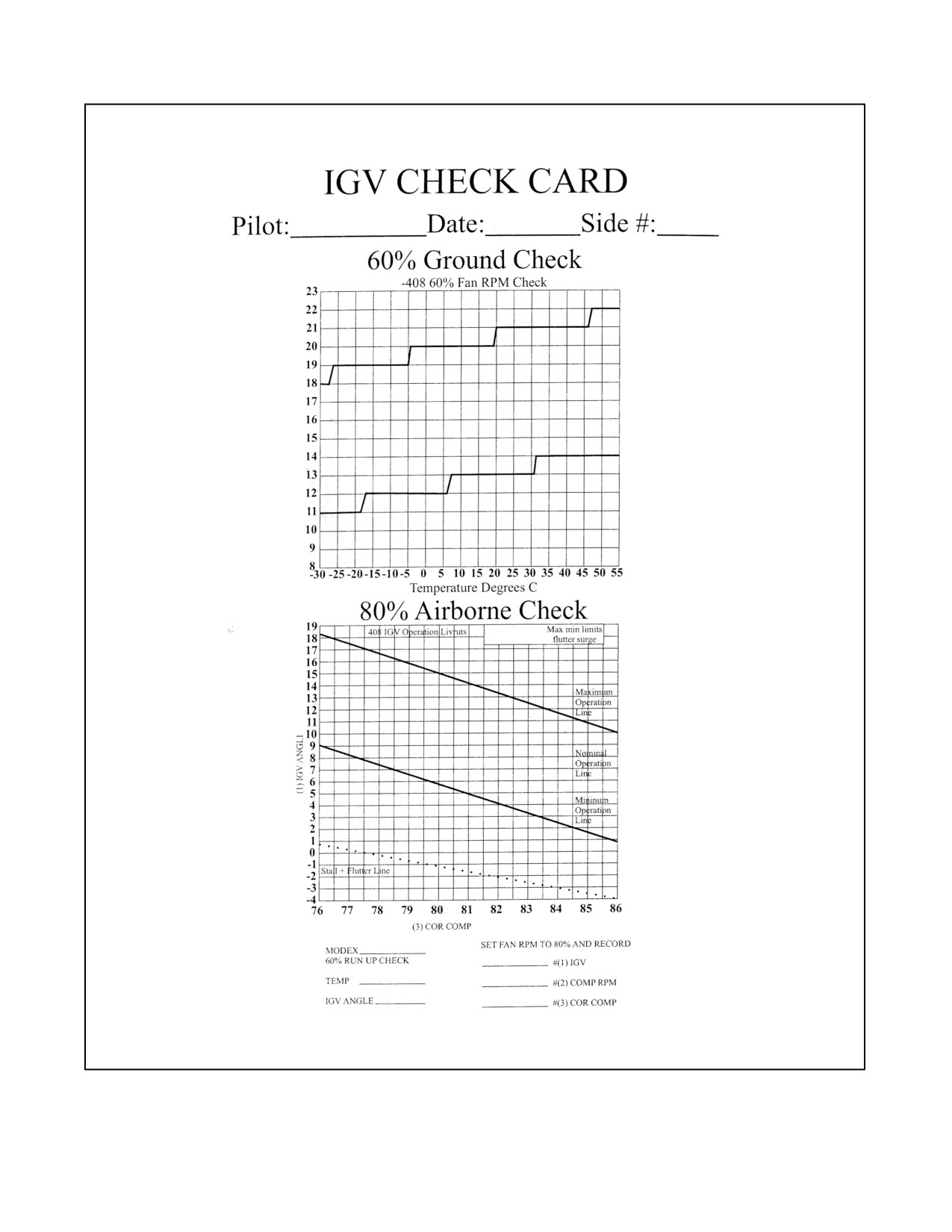
Figure 7-2. 60/80% Check Card for --408A
ORIGINAL
7-38
A1-AV8BB--NFM--000
9. Nozzle/Flaps/Duct Pressure — CHECK.
a. Set nozzles momentarily to approximately 50°.
b. Check flaps at approximately 62°.
c. Check duct pressure approximately 45 psi.
d. Place nozzles at the Hover Stop and check angle.
Initiate Takeoff:
10. Throttle — FULL.
11. Brakes — HOLD until airborne.
12. CHECK TOP END RPM and Water Flow (if armed).
13. During liftoff — ensure wings remain level. Hold heading and adjust attitude to prevent fore/aft drift.
14. When clear of ground effect (20 to 25 feet), gradually reduce power to establish a hover, or when passing 50
feet and clear of obstacles, begin transition to wingborne flight (see paragraph 7.3.2.4 Accelerating Transition).
7.3.2.2 Rolling Vertical Takeoff
An RVTO may be performed in those instances when a VTO is desired but the takeoff surface is deemed unsuitable.
The RVTO requires approximately 100 feet of ground roll and should be made as nearly into the wind as possible.
RVTO can be performed up to hover weight as calculated in Performance Data, A1--AV8BB--NFM--400. The Mission
Computer VREST function does not provide hover weight calculation, so VTO weight should be used as a
conservative estimate.
Configuration Checks (One Finger Checks):
1. Nozzle Rotation Airspeed (NRAS) — NOT REQUIRED.
2. Pitch Carets (PC) — SET.
3. STO Set — 70°.
4. Trim — SET.
5. Flaps — STOL.
6. Warning/caution lights — OUT.
Engine, Water System and Flight Control Checks (Two/Five Finger Checks):
7. Engine — CHECK.
8. Water — AS REQUIRED.
9. Nozzle/Flaps/Duct Pressure — CHECK.
a. Set nozzles momentarily to STO Stop and check angle.
b. Check flaps at approximately 62°.
c. Check duct pressure approximately 45 psi.
d. Place nozzles to 30°.
7-39
ORIGINAL
A1-AV8BB--NFM--000
Initiate Takeoff:
10. NWS — ENGAGE.
11. Throttle — FULL.
12. Brakes — RELEASE (no later than at initial tire skid).
13. Nozzles — STO STOP AS RPM PASSES -- 100 percent (--406 engine) -- 110 percent (--408 engine).
14. During liftoff ensure wings remain level and center the sideslip vane.
15. Begin transition to wingborne flight (see paragraph 7.3.2.4 Accelerating Transition).
7.3.2.3 Short Takeoff
The STO can be used for the widest variety of aircraft configurations, weights and runway conditions provided that
crosswinds remain within specified limits. Nozzle rotation airspeed (NRAS) and nozzle angle calculation can be
performed using Performance Data, A1--AV8BB--NFM--400, Mission Planning System (MPS), or the Mission
Computer VREST function.
CAUTION
When the takeoff surface is littered with hard foreign objects such as rocks
or stones and takeoff conditions permit, the use of AUTO flaps is
recommended to reduce the potential for flap damage due to debris impact.
VREST data is invalid for AUTO flap STOs.
Configuration Checks (One Finger Checks):
1. Nozzle Rotation Airspeed (NRAS) — SET AS CALCULATED.
2. Pitch Carets (PC) — SET.
3. STO Stop — SET AS CALCULATED.
4. Trim — SET.
5. Flaps — AS DESIRED (STOL or AUTO).
6. Warning/Caution Lts — OUT.
Engine, Water System and Flight Control Checks (Two/Five Finger Checks):
7. Engine — CHECK.
8. Water — AS REQUIRED.
9. Nozzle/Flaps/Duct Pressure — CHECK.
a. Set nozzles momentarily to STO Stop and check angle.
b. Check flaps for proper angle based on flap mode.
c. Check duct pressure approximately 45 psi.
d. Place nozzles at 10°.
ORIGINAL
7-40
A1-AV8BB--NFM--000
Initiate Takeoff:
10. NWS — Engage.
11. Throttle — FULL.
12. Brakes — Release (no later than at initial tire skid).
13. CHECK TOP END RPM and Water Flow (if armed).
14. Nozzles — STO Stop at calculated NRAS.
15. During liftoff — ensure wings remain level and center the sideslip vane.
16. Begin transition to wingborne flight (see paragraph 7.3.2.4 Accelerating Transition).
7.3.2.4 Accelerating Transition
Accelerating transition is the term used to describe transition from jetborne/semi--jetborne flight to wingborne flight.
The accelerating transition begins once the aircraft is clear of ground effect and at an altitude sufficient to avoid
obstacles and introduction of FOD onto the landing surface. A slight climb should be maintained throughout the
transition manuever. Accelerating transitions are performed using a capture attitude technique -- meaning the aircraft
is rotated in pitch until the depressed attitude symbol, or Witches Hat, coincides with the pitch carets. The capture
attitude technique decreases pilot workload, as well as reducing the probability of having AOA excursions early in
the takeoff maneuver due to pilot induced pitch oscillations.
During accelerating transitions, angle of attack must not exceed 15°.
Overrotation or high rotational rates may result in the AOA rising
uncontrollably even with the stick full forward. Uncontrollable pitch ups
are most likely to occur at extreme aft CG loadings and/or with the wing
flaps deflected more than 25°.
1. Throttle — FULL.
2. Set attitude — Witches hat at the pitch carets (Continue to maintain wings level and vane centered).
3. Nozzles — gradually rotate the nozzles aft. Nozzle rotation rate should enable the aircraft to maintain a slight
climb. (Maintain a nozzle angle of 25° or greater while in STOL flaps).
Note
Steps 2 and 3 are performed simultaneously, so that the effective nozzle
angle with respect to the ground does not increase when the attitude is being
set.
Once wingborne flight is achieved:
4. Reduce power in order to achieve the normal lift dry rating or less (extinguish the 15 sec light) and stop water
flow (if required).
5. Perform After Takeoff check or enter the landing pattern.
7-41
ORIGINAL
A1-AV8BB--NFM--000
CAUTION
Uncommanded nosewheel steering angle excursions may occur if after
lift--off an immediate turn is made. With lift--off above 100 KGS, the
nosewheel may cant to such a degree that undesirable ground handling
characteristics may occur on touch down. Extending upwind for approxi-
mately 10 to 15 seconds while rotational speed slows down can minimize
this gyroscopic effect.
7.3.3 Conventional Takeoff
The CTO can be used when configuration or environmental conditions preclude use of any other takeoff type (i.e.,
crosswinds or asymmetric loadings). The CTO is restricted to gross weights that will not cause the wheel/tire
limitation speed of 180 KGS to be exceeded on thetakeoff roll. Refer to Performance Data, A1--AV8BB--NFM--400.
The Mission Computer VREST function does not provide CTO performance calculations.
Configuration Checks (One Finger Checks):
1. Nozzle Rotation Airspeed (NRAS) — SET NOSEWHEEL LIFTOFF SPEED.
2. Pitch Carets (PC) — SET.
3. STO Stop — CLEAR.
4. Trim — SET.
5. Flaps — AUTO.
6. Warning/Caution Lts — OUT.
Engine, Water System and Flight Control Checks (Two/Five Finger Checks):
7. Engine — CHECK.
8. Water — AS REQUIRED.
9. Nozzle/Flaps/Duct Pressure — CHECK.
a. Set nozzles momentarily to approximately 50°.
b. Check flaps at approximately 25°.
c. Check duct pressure approximately 45 psi.
d. Place nozzles to 10°.
Initiate Takeoff:
10. NWS — Engage.
11. Throttle — FULL.
12. Brakes — Release (no later than at initial tire skid).
13. CHECK TOP END RPM and Water Flow (if armed).
14. At nose wheel liftoff speed — Gradually rotate with aft stick. Guard against over--rotation.
ORIGINAL
7-42
A1-AV8BB--NFM--000
15. During liftoff — ensure wings remain level and center the sideslip vane.
16. Set attitude — Witches hat at the pitch carets.
CAUTION
Uncommanded nosewheel steering angle excursions may occur if after
lift--off an immediate turn is made. With lift--off above 100 KGS, the
nosewheel may cant to such a degree that undesirable ground handling
characteristics may occur on touch down. Extending upwind for approxi-
mately 10 to 15 seconds while rotational speed slows down can minimize
this gyroscopic effect.
7.3.4 Formation Takeoff
7.3.4.1 Formation Vertical Takeoff
Formation Vertical Takeoff is not recommended.
7.3.4.2 Formation Rolling Vertical Takeoff
Formation Rolling Vertical Takeoff is not recommended.
7.3.4.3 Section STO
The Section STO provides the capability to launch a section of aircraft using the STO technique when conditions
make the time required to execute a formation rendezvous unacceptable or undesirable (i.e., low ceilings or poor
visibility). Aircraft conducting Section STOs should be likeconfigured (enginetype and gross weight). Line up with
a minimum lateral separation of one wingspan. The wingman shall be upwind with intakes forward of the leader’s
cold nozzles. The flight shall use the highest calculated NRAS and its corresponding nozzle rotation angle.
1. Takeoff checks — TWO/FIVE FINGER CHECKS COMPLETE.
2. Signal two or five fingers to flight lead.
Leader nods head:
3. Brakes — RELEASE.
4. Throttle — ADVANCE SMOOTHLY TO MAX RPM.
At NRAS leader nods head:
5. Nozzles — STO STOP.
6. Begin transition to wingborne flight while maintaining formation position (see paragraph 7.3.2.4 ).
When wingborne flight is achieved:
7. Flight lead nod head to initiate After Takeoff checks (see paragraph 7.3.5).
Section STOs should not be conducted a night.
7-43
ORIGINAL
A1-AV8BB--NFM--000
7.3.4.4 Section CTO
The Section CTO provides the capability to launch a section of aircraft using the CTO technique when conditions
make the time required to execute a formation rendezvous unacceptable or undesirable (i.e., low ceilings or poor
visibility). Aircraft conducting Section CTOs should belikeconfigured (enginetype and gross weight). Line up with
a minimum lateral separation of one wingspan. The wingman shall be upwind with intakes forward of the leaders
cold nozzles. The flight leader should use the rotation speed of the heaviest aircraft.
1. Takeoff checks — TWO/FIVE FINGER CHECKS COMPLETE.
2. Signal two or five fingers to flight lead.
Leader nods head:
3. Brakes — RELEASE.
4. Throttle — ADVANCE SMOOTHLY TO MAX RPM THEN LEAD SETS.
a. 93 percent rpm (--406 engine).
b. 100 percent rpm (--408 engine).
Just prior to rotation airspeed, flight leader gives go fly signal:
5. Wingman matches lead’s rotation rate and maintains lateral separation.
After safely airborne, flight leader nods head:
6. Initiate After Takeoff checks (see paragraph 7.3.5).
7. Wingman closes to standard parade position.
7.3.4.5 Section Stream STO or Division Stream STO
When multiple aircraft need to be launched together, but ceilings and visibility are great enough to permit a
rendezvous underneath, then a Section or Division Stream STO can be used. Aircraft conducting Stream STO need
not be identically configured. Line up on the runway with the flight lead on the downwind side with a minimum
distance between aircraft of 1,000 feet. Each succeeding aircraft should be staggered diagonally. On signal, all the
aircraft roll simultaneously and perform individually computed STO. (The flight lead transmits calculated
NRAS/STO STOP values only as a cross check for the flight.) When safely airborne, the flight leader reduces power
slightly to expedite the rendezvous.
CAUTION
Do not enter the jetwash of preceding aircraft during climbout.
Flight Leadertransmits “LEAD (Left/Right side), STREAM STO, (calculated NRAS value), (calculated STO STOP
value), (Wet/Dry)”:
1. Once in position with one finger checks complete — REPORT “(number in flight) ONE FINGER”.
Flight Leader directs “RUN’EM UP”:
2. Two/Five Finger Checks — REPORT “(number in flight) TWO/FIVE FINGER”.
Leader transmits “ROLLING, ROLLING, GO”:
3. Perform a normal STO on individually calculated numbers.
ORIGINAL
7-44
A1-AV8BB--NFM--000
4. Transition to wingborne flight (see paragraph 7.3.2.4 Accelerating Transition).
5. Initiate After Takeoff checks (see paragraph 7.3.5).
6. Execute formation rendezvous or deploy to assigned position.
7.3.4.6 Radar Trail Departure
Radar Trail Departures. Radar trail departure is normally used to get a flight of two or more airborne (4 is the
maximum allowed by OPNAV 3710) under IMC conditions. Local training flights requiring a DD--175 will need to
request non--standard formation in the remarks section. Circling minimums will be required. Airspeed is the primary
means for separation, using the radar to fine tune formation keeping. Aircrew will not begin radar switchology until
their aircraft is cleaned up.
Prior to Takeoff:
Set radar parameters to range while scan (RWS)/4bar/90°/10nm/MPRF/4 sec. aging, (use 6 bar for division takeoffs),
verify antenna coverage. Ensure the radar is not in the BIT cycle and all parameters are set prior to taking the runway.
Departure:
The primary mode of radar trail departures from a visual start (under the overcast) will be via BACQ or GACQ, and
then follow in STT. TWS should be avoided because it takes too long to extrapolate targets. Radar trail departures
will be conducted from an individual takeoff profile. A 30 second interval should give a 2 nm separation between
aircraft.
If trail is to be accomplished under a cloud layer with intent for an IMC climb, dash--2, once safely airborne, can select
either BACQ or GACQ and visually place the leader in the scan volume which will command STT. Once radar lock
is verified visually and with range/altitude, the wingman calls “tied”. The wingman further repositions himself to
a 1--2 nm trail.
If desired, a trail departure may be done as separate elements. From a 30 second interval as before, dash 2/3/4, once
safely airborne, will monitor the flight via the RWS parameters stated earlier. The wingmen maintain 2 nm separation
with AA TACAN, radar, and airspeed. As lead makes a turn, the wingmen lag all turns following the same flight
profile as lead rather than decreasing nose to tail. This is done by allowing the preceding aircraft to drift 5° laterally
for each mile if separated prior to starting the turn. For example, for 1 nm trail, let the lead/interval drift 5°, for 2 nm
trail, let the lead/interval drift 10°, and so on. Monitor Vc in the HUD or RADAR display and the airspeed of your
interval to ensure that you are not closing or opening. Lead and lag turns appropriately to maintain the correct 2 nm
spacing. Appropriate lag pursuit curves may be used to adjust distance (lead pursuit should be avoided due to
excessive closures without a visual). This profile will continue until a visual join--up on top can be accomplished.
Echelon formation will have the lead 30° left/right on the scope with approximately 170° target aspect, and range
will auto scale to better display 1--2 nm range to lead. Pure trail formation will show the leader on the nose with 180°
aspect.
If radar contact is lost, call “clean” if using RWS, or call “broke lock” if using STT. Select GACQ (visual) or RWS
(IMC) for reacquiring the lead. If a flight member is clean or breaks lock, the flight lead will call all turns and
headings, as well as passing each 5,000 feet of altitude change.
In division it is recommended that BACQ be used to more discriminately lock the next element (i.e., dash--3 locks
dash--2) if visibility/ceiling permits. If the weather causes you to be unable to visually confirm the lock, then the RWS
format described above will enable the pilot to see all elements of the flight. Once the flight has been detected, the
pilot must sort the formation and command a manual acquisition of his interval.
7-45
ORIGINAL
A1-AV8BB--NFM--000
D Positive deconfliction must be made within a division to ensure “simo”
joins on an element do not occur. This maybe done by verifying rangewith
AA TACAN and comm. Using RWR (buddy spikes) at these ranges will
not give adequate confirmation.
D Once radar contact is established, the pilot may fly the profile in either RWS
orSTT.UsingtheRWSmodewillbemoredifficult andlost detectionsmay
occur. STT will be the simplest method of precisely keeping position
during the climbout but will keep the wingman blind to all other traffic. In
all cases the wingman will be required to maintain the same ground track
as the lead, hence the requirement for lag pursuit.
7.3.5 After Takeoff
1. Landing Gear — UP.
2. Flaps — AUTO.
Selection of AUTO flaps shall be made when comfortably airborne at no less than 25° nozzle angle.
3. Nozzles — AFT.
4. Water switch — OFF.
5. STO Stop — CLEAR.
CAUTION
After takeoff, do not apply wheel brakes prior to, or as part of raising the
landing gear. Applying wheel brakes immediately after takeoff while the
wheels are spinning places undue stress on the main landing gear system
and may cause the main landing gear door to be pulled into the main wheel
well. If the main landing gear doors are jammed, the main landing gear will
not extend when the landing gear handle is lowered resulting in a main
landing gear up landing.
Note
With the landing gear up, the JPT limiters will throttle the engine back to
the maximum thrust rating when nozzle angle is reduced below 7° to 12°.
If operating near lift ratings (particularly on a wet takeoff), this sudden and
large thrust reduction must be anticipated or the last 20° of nozzle rotation
delayed until after power has been reduced with the throttle.
6. VTR — AUTO OR RUN AS REQUIRED.
7.3.6 CLIMB Performance Data
A1--AV8BB--NFM--400 specifies a simplified climb technique consisting of a constant airspeed climb until
interception of the specified Mach number, at which point a constant Mach climb is initiated. The initial phase of
ORIGINAL
7-46
A1-AV8BB--NFM--000
the climb is normally conducted at 300 KCAS, unless there is intent to level off and cruise below 10,000 feet MSL,
in which case the climb can be conducted at 250 KCAS.
7.4
INFLIGHT
Periodic checks of engine displays, fuel quantity, and instruments must be made to detect system anomalies early
on. Fuel asymmetry must be monitored to prevent development of asymmetric loads.
Note
Refer to Flight Characteristics, Chapter 11; All Weather Operation, Chapter
20; and Performance Data, A1--AV8BB--NFM--400.
7.4.1 10,000 Foot Check
1. Fuel transfer/quantity.
2. Cabin pressure.
7.4.2 18,000 Foot Check
1. Altimeter — 29.92 SET.
2. Cabin pressure.
3. APU secure if conditions permit.
7.4.3 IGV Check (--408A or --406 engine only)
This check should be performed at 5,000 feet MSL.
1. Set engine fan speed to 80 percent RPM.
2. Data — Record required data on card (Figure 7-2).
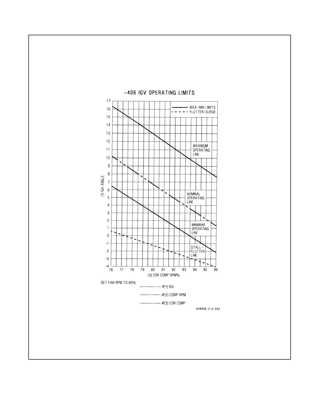
3. IGV Angle — Within bands indicated (Figure 7-3).
4. If IGV angle above indicated boundary execute IGV failure procedure for IGVs stuck at high angle.
5. If IGV angle below indicated boundary execute IGV failure procedure for IGVs stuck at low angle.
If the in--flight check results in an IGV angle for a given Cor Comp RPM
value that falls on or outside of the minimum/maximum operating lines,
treat as an IGV failure.
7.5
DESCENT
Perform the following checks before commencing descent:
1. STO Stop — CLEAR.
2. Weather — CHECK (ATIS information).
a. Verify wind speed and direction.
b. Verify ceiling and visibility.
c. Determine approach and landing suitable for weather and aircraft configuration.
7-47
ORIGINAL
A1-AV8BB--NFM--000
3. Instruments — Set--up.
a. STP — Set to intended point of landing.
b. TCN — Set to airfield/ship or A/A TCN per brief.
c. Courseline — Set to runway heading or approach Final Approach Course.
d. NAVFLIR, HUD, RADALT — Set to desired configuration for cueing to landing environment.
4. Fuel — CHECK.
a. Reset BINGO bug to briefed setting.
b. Balance asymmetry if greater than 300 pounds.
5. Temperature — PREHEAT/DEFOG (as required).
6. APU — AS REQUIRED (see Chapter 4, Figure 4-7).
7.6
LANDING
The break speed is 350 KCAS. The standard break interval is 2 seconds. VFR Straight--in--recoveries should be
accomplished using an en route formation to the initial point. The flight may be separated either in a clean or dirty
configuration. To separate the flight in the clean configuration, once established on extended final and with the field
in sight, wingmen should be detached by the flight leader at 2 nm intervals. 4 ship formations should detach dash
4 at 8 nm, dash 3 at 6 nm, and dash 2 at 4 nm to allow lead the ability to transition to the landing configuration 2 nm
prior to the landing threshold. Once detached, each flight member should ensure airspeed is below 250 KCAS,
transition to the landing configuration, select 25° nozzles, flaps as required, and slow to 8 to 10 degrees AOA. At
2 nm flight members should select 60 degrees nozzles (or as required for type landing) and slow to 10 to 12 degrees
AOA. To separate the flight in a dirty configuration, once established on extended final and with the field in sight,
the flight leader should lower landing gear as a flight. 4 ship formations should detach dash 4 at 7 nm, dash 3 at 5
nm, dash 2 at 3 nm. Once detached each flight member should select hover stop until approaching 8 to 10 degrees
AOA then reset nozzle angle to 60 degrees (or as required for type landing). The flight leader may provide the signal
to detach from the formation either via radio or visually. Flight members should strive to maintain interval between
aircraft once separated from the formation and fly a 3 degree glide slope, but at no time fly below the flight path of
the aircraft in front of them. Landings are normally made to centerline, and beyond the landing touch down point
of the preceding aircraft. Once comfortable, flight members should move to the side of the runway of expected exit
in order to provide an avenue for aircraft landing behind experiencing brake failure. FOD awareness and proper FOD
prevention intervals should always be maintained.
The break speed is 350 KCAS. The standard break interval is 2 seconds. At the break, apply bank angle, retard the
throttle and extend speed brake. Once below 250 KCAS, complete the Landing Checklist (7.6.1). Four methods of
landing are possible. These are Vertical Landing (VL), Rolling Vertical Landing (RVL), Slow Landing (SL) and
Conventional Landing (CL). The method of landing is dependent upon tactical and other conditions and must be
predetermined in order to properly configure the aircraft. In the case of VLs and RVLs, it is also necessary to calculate
landing performance using Performance Data, A1--AV8BB--NFM--400 or the Mission Computer VREST calculator.
A decelerating transition from wingborne flight is used to place the aircraft in position for a VL or an RVL. All other
landing types use a standard pattern approach to landing. On all rolling landings (CL, SL, RVL) the recommended
landing attitude is to place the depressed attitude symbol (Witches Hat) on to 2° above the horizon bar. Pilots should
expect turbulence and random trim changes when the aircraft enters ground effect (below 20 to 25 feet) as jet efflux
strikesvarious airframesurfaces, theaircraft mustbeactivelyflown allthewayto theground. Priorto engagingNWS
ensure the aircraft is tracking straight and the rudder pedals are centered. Power Nozzle Braking (PNB) is normally
used for most roll--on landings; however, the aircraft can be stopped using wheel brakes alone. If wheel brakes alone
are used after landing at speeds greater than 140 KGS and above 20,000 LBS GW, the pilot should expect main tire
fuse plug release approximately one minute after the aircraft comes to a stop. To achieve minimum braking distance,
the anti--skid system operates most efficiently when the brakes are applied 2 seconds after touchdown using a quick,
full pedal input held steady until taxi speed is reached. Do not cycle, pump or lightly ride the brakes. For crosswind
landing techniques and considerations, refer to Chapter 11, Crosswind Landing Operations.
ORIGINAL
7-48
A1-AV8BB--NFM--000
Figure 7-3. 65% Check Card for --406A
7-49
ORIGINAL
A1-AV8BB--NFM--000
7.6.1 Landing Checklist
The following landing checklist is used to configure the aircraft for all four of the landing methods.
Note
Each aircraft cockpit contains a landing checklist placard. The content of
these placards varies substantially from the current version described in this
manual.
1. Gear — DOWN.
2. Flaps — AS REQUIRED (nozzles 25° or greater prior to selecting STOL flap).
3. STO Stop — CLEAR.
4. Duct pressure — CHECK.
5. Brake pressure — CHECK.
6. Water — AS REQUIRED.
If water is to be used:
a. Nozzles — AS REQUIRED.
b. Water switch — T/O (check for RPM rise).
c. Throttle — 105 PERCENT MINIMUM.
d. Check for green water flow light or W in the HUD, and water quantity countdown.
e. Water switch — AS REQUIRED.
D Proper performance of the water check is not a guarantee that the system
will activate and provide water flow later in the landing evolution. It is
essential that RPM, JPT and flow status be monitored if wet performance
is required.
D Failure of the water non--return valve may cause cavitation of the water
pumpresultingin lossofthrustwithout associatedwarning indications(i.e.
water flow light on but no flow). Monitoring JPT is considered crucial for
awareness of proper water system operation.
7. VTR — RUN.
8. Warning and caution lights — CHECK.
9. Lights — AS REQUIRED.
ORIGINAL
7-50
A1-AV8BB--NFM--000
On aircraft after AFC--391
(NWS Mod), it is imperative that the
ANTISKID switch be reset to ON. Landing with the ANTISKID switch in
NWS will result in the loss of antiskid protection during the landing and
will additionally result in the unintended selection of hi gain steering if the
NWS button on the stick is depressed and held with throttle below about
75 percent fan speed.
7.6.2 Decelerating Transition to a Hover
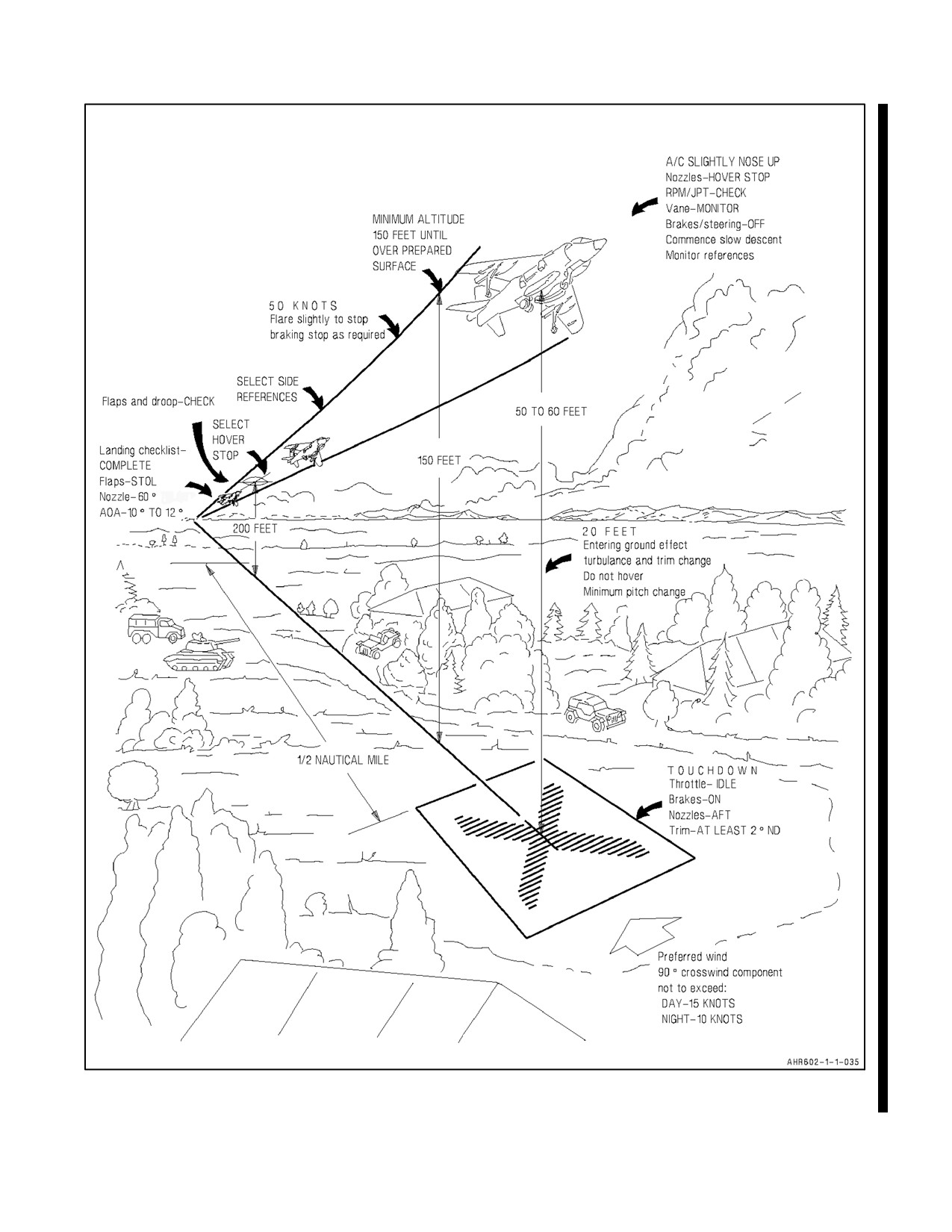
Decelerating transitions for VLs are started from a key position approximately 1/2 NM from the touchdown point
(preferably downwind) at an altitude of approximately 310 feet AGL. This places the aircraft on a slightly descending
flight path toward a point abeam the intended point of landing at approximately 150 feet AGL. From, or just prior
to arrival at, this abeam position, the aircraft then crosses to hover directly over the intended point of landing. (See
Figure 7-4.)
Approaching 180:
1. Nozzles — 60°.
2. Flaps — CHECK PROGRAMING AND DROOP.
3. AOA — 10° TO 12°.
Off the 180:
4. Adjust flight path with stick.
5. Control AOA with throttle or nozzles.
At the Key:
6. Set attitude — WITCHES HAT ON THE HORIZON.
7. Nozzles — HOVER STOP.
8. Minimize sideslip, ensure no more than 15° AOA and strive for 0° AOB until less than 30 knots. Increase
power as required to maintain a shallow glideslope (approximately 3°) to arrive abeam the landing site at 150
feet AGL.
At 60 KCAS:
9. Check for adequate performance margin — if more than two legs of the power hexagon then execute a waveoff.
Note
Due to numerous dynamic factors associated with every approach, a valid
60 knot check does not guarantee acceptable performance will remain for
the hover and vertical landing. 60 knot check validity is improved by
having the velocity vector on the horizon, a proper attitude and a steady
state power condition when approaching the check airspeed.
7-51
ORIGINAL
A1-AV8BB--NFM--000
10. Approaching landing site — Select ground references and monitor rate of closure. When closure is under
control and below 30 knots, cross over the landing site while remaining at 150 feet AGL minimum until over
a prepared surface. Flare slightly to stop, or use braking stop as required, and establish hover over the desired
landing point.
7.6.3 The Hover
The hover may be entered from a decelerating transition or a VTO. It is an interim period during which the aircraft
is held relatively stationary at an altitude of 50 to 60 feet AGL.
1. Control height with small throttle changes.
2. Maintain position with ground references.
3. RPM/JPT — WITHIN LIMITS.
7.6.4 Vertical Landing
The vertical landing, Figure 7-4, is commenced from a 50 to 60 foot AGL hover. Landing should be made pointing
into the wind to minimize exhaust reingestion.
1. Start a slow descent with the throttle.
2. Monitor ground references.
3. Maintain heading and adjust attitude and roll as necessary to correct for drift.
4. Maintain positive rate of descent. Avoid stopping in ground effect. Some throttle reduction may be required
if descent rate is slow sincethe aircraft will tend to stop in thearea ofmaximum LIDS capability (5 to 10 feet).
Additionally, surface winds in excess of 10 knots may degrade LIDS performance and may require a
corresponding coarse power correction just prior to touchdown.
Note
If strakes or gun pods are not installed some suck--down effect is present.
A power increase may be required near touchdown to prevent excessive
sink rate.
When positively down:
5. Throttle — IDLE.
6. Brakes — APPLY.
7. Nozzles — AFT.
8. Trim — 4° ND.
9. Water — OFF (if selected).
Note
Do not hover in ground effect. Avoid large pitch changes near ground to
prevent hot gas reingestion and hitting the tail bumper.
ORIGINAL
7-52
A1-AV8BB--NFM--000
(below 165 knots)
Figure 7-4. Vertical Landing
7-53
ORIGINAL

A1-AV8BB--NFM--000
7.6.5 Decelerating Transition to a Rolling Vertical Landing
The RVL should be used when the landing surface isn’t long enough to support a SL, but the landing area cannot
support a VL because it is subject to damage from heating or is a source of FOD. A ground speed of five to ten knots
is sufficient to avoid overheating and damaging asphalt in good condition. However, a ground speed of 60 knots or
higher will be required if FOD is a major concern. (At this speed objects blown up at touchdown will remain behind
the intake suction doors.) Decelerating transitions for RVLs are started from a key position approximately 3/4 nm
from the touchdown point at an altitude of approximately 310 feet AGL. At the key the aircraft attitude and estimated
nozzleanglearesetwhileacrabbed approachis usedto maintainrunway centerline.Theaircraftis flownon aslightly
descending flight path (approximately 3°) until the touchdown point reaches the desired level of depression in the
HUD. At this point, flight path can be adjusted to ensure precise landing on centerline and at the desired point.
Workload is increased slightly over the SL, particularly when making an approach into short runways or confined
areas. Such approaches require both precise centerline control and accurate control of the touchdown point by
variation of the glide slope. Care must be taken to avoid making a play for the intended point of touchdown or
checking back on the stick in close as these actions inevitably increase sink rate and cause the aircraft to bounce or
rock forward onto the nosewheel. Normally a glideslope of three degrees will satisfy the need to control touchdown
point and rollout distance. However, a steeper glideslope, up to 6 degrees, may be necessary when approaching over
significant obstacles into fields short enough to dictate touchdown as close to the threshold as possible. If runway
distance is critical and FOD potential is low, ground speeds slower than 60 knots should be considered. Performance
Data, A1--AV8BB--NFM--400, will permit the pilot to calculate max gross landing weight and nozzle angle for a
desired RVL approach speed. However, since RVL capability is directly related to VL capability, the following
relationships can be used (number based on STOL flaps, 10° AOA and nozzle angle as required to maintain KCAS).
TOUCHDOWN SPEED (KCAS)
MAXIMUM RVL WEIGHT
(ALL ENGINES, WET/DRY)
≤45 knots
VL weight
50 knots
VL + 2,300 pounds
55 knots
VL + 2,700 pounds
60 knots
VL + 3,100 pounds
65 knots
VL + 3,500 pounds
70 knots
VL + 4,000 pounds
Note
When targeting ground speed during an RVL, pilots must consider wind
speed and direction to endure that KCAS does not fall below that required
to maintain performance margin. Tail winds, steep descent angles and
higher ground speeds will increase descent AOA and may necessitate a
reduction in attitude or a change in other parameters in order to maintain
the 15° AOA limit.
Approaching 180:
1. Nozzles — 60°.
2. Flaps — Check programming and droop.
3. AOA — 10° TO 12°.
Off the 180:
Adjust flight path with stick Control AOA with throttle or nozzles.
ORIGINAL
7-54
A1-AV8BB--NFM--000
At the Key:
4. Set attitude — Witches hat on the horizon.
5. Nozzles — AS REQUIRED, adjust to maintain desired ground speed.
6. Minimize sideslip, ensure no more than 15° AOA.
7. Adjust power to intercept desired glideslope to touchdown point.
At touchdown:
8. Throttle — IDLE.
9. Nosewheel steering — ENGAGE WHEN ROLLING STRAIGHT AND PEDALS ARE NEUTRALIZED.
10. Nozzles — AS SET.
11. Brakes — APPLY.
12. Trim — MINIMUM 2° ND.
13. Water — OFF.
14. Nozzles — LESS THAN 60° WHEN SLOW.
7.6.5.1 Slow Landing
The SL may be used when aircraft gross weight is too high for a VL or RVL or to reduce engine stress. Performance
calculations are required for heavy gross weights or short strips. There are four basic types of Slow Landings, the
specifictypebeing defined by acombination offlap position (STOL orAUTO)and whetherthenozzles remain fixed
during the approach or are varied as the primary means of airspeed control. These slow landing types are referred
to as the Auto Flap Fixed Nozzle Slow Landing (AFNSL), STOL Flap Fixed Nozzle Slow Landing (SFNSL), Auto
Flap Variable Nozzle Slow Landing (AVNSL), and STOL Flap Variable Nozzle Slow Landing (SVNSL). Any of
these four SL types can be modified at the in close position by application of Hover Stop or Braking Stop. (See
paragraph 7.6.5.2.1 Hover Stop Slow Landing/Braking Stop Slow Landing.)
7.6.5.1.1 Fixed Nozzle Slow Landing
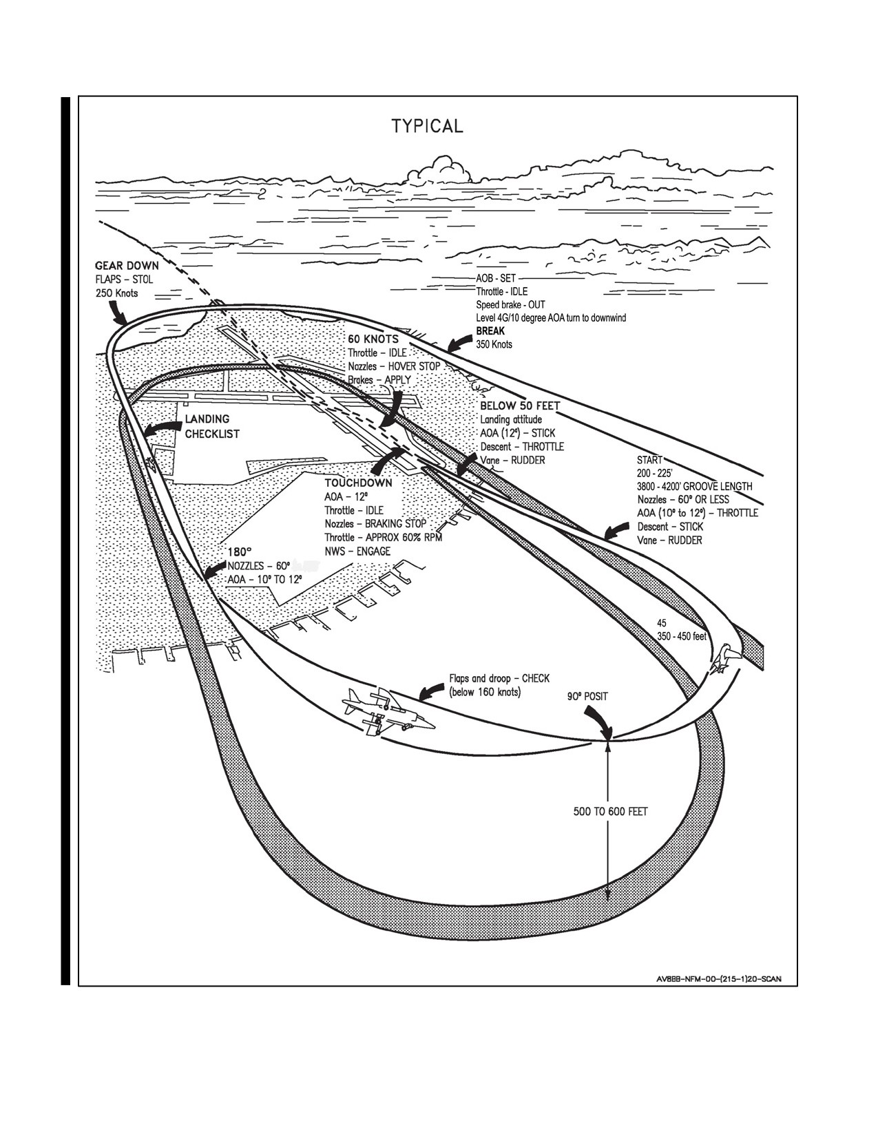
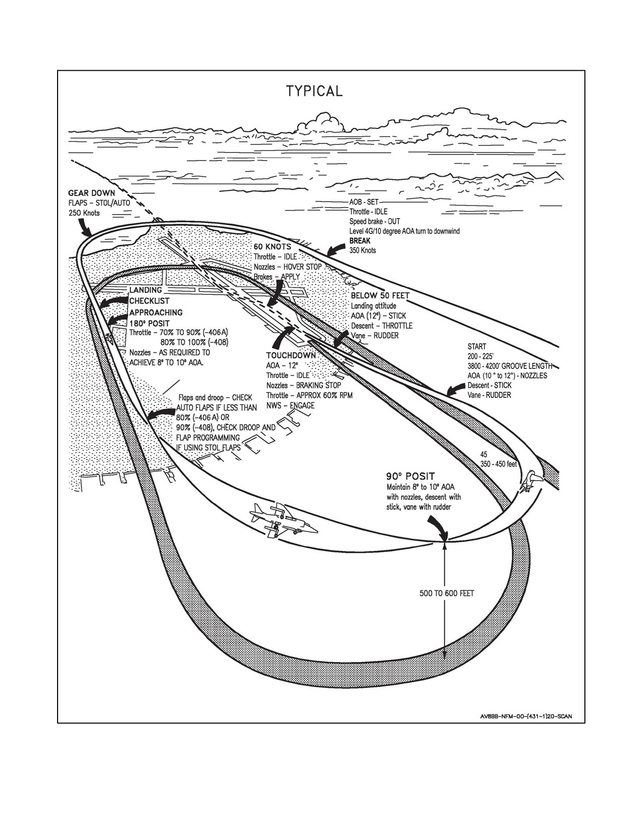
The STOL Flap — FNSL, Figure 7-5, is the recommended slow landing technique and is the procedure on which
the Short Landing Distance Chart in A1--AV8BB--NFM--400 is based. It is significantly easier to accomplish than
a VNSL, requires less fuel for an approach and very nearly approximates the landing speeds of the variable nozzle
approach. With high temperature and pressure altitude and at heavy gross weight, care must be exercised as waveoff
capability may be degraded. The AFNSL is also simple to fly but will produce a substantially higher approach speed
and landing rollout. This approach is normally used when crosswind conditions preclude a landing below 140 KCAS
or when dealing with high asymmetric store loadings. The same landing approach path is used for either technique.
(See Figure 7-5.)
Approaching 180:
1. Nozzles — 60°.
2. Flaps — Check programming and droop.
3. AOA — 10° TO 12°.
Note
If power exceeds 92 percent rpm for the --406 engine or 100 percent rpm
for the --408 engine a lower nozzle angle should be used.
7-55
ORIGINAL
A1-AV8BB--NFM--000
Off the 180:
4. Adjust flight path with stick.
5. Control AOA with throttle.
At 30 to 50 feet AGL:
6. Set Attitude — Witches Hat on to 2° above the horizon.
7. Control ROD with throttle (200 to 400 fpm).
At touchdown:
8. Throttle — IDLE.
9. Nosewheel Steering — ENGAGE WHEN ROLLING STRAIGHT AND PEDALS ARE NEUTRALIZED.
10. Nozzles — AS REQUIRED (up to full braking stop).
11. Trim — MINIMUM 2° ND.
12. Throttle — AS REQUIRED (for PNB a maximum of 60 percent (--406) to 70 percent (--408)).
At 60 kts:
13. Throttle — IDLE.
14. Nozzles — HOVER STOP.
15. Brakes — APPLY.
16. Water — OFF.
17. Nozzles — LESS THAN 60° WHEN SLOW.
7.6.5.2 Variable Nozzle Slow Landing
The variable nozzle slow landing (VNSL) is used whenever the throttle needs to remain at a relatively constant setting
throughout the approach. There are numerous reasons why the pilot might elect to set a constant power setting. A
SVNSL with a high end throttle setting may be flown when attempting to perform a slow landing at the minimum
practical airspeed. In other cases, the pilot may elect to set power when engine reliability is suspect. The same landing
approach path is used for either technique. (See Figure 7-6.)
Note
Using STOL flaps requires a power setting high enough to prevent the
selection of nozzle angles less than 50°, but low enough to allow excess rpm
for waveoff capability. If less than 50 nozzles are used when in STOL flaps,
theflapswillraiseandwing liftwill belost. Accordingly,AUTO flapsshall
be used for VNSL if rpm is set less than 80 percent (--406 engine) or 90
percent (--408 engine).
ORIGINAL
7-56
A1-AV8BB--NFM--000
Approaching 180:
1. Nozzles — 40° TO 60°.
2. Throttle:
a. 70 to 90 percent (--406 engine).
b. 80 to 100 percent (--408 engine).
c. Nozzles — AS REQUIRED TO ACHIEVE 8° TO 10° AOA.
d. Flaps — CHECK PROGRAMING AND DROOP.
Off the 180:
3. Adjust flight path with stick.
4. Control AOA with nozzles.
At 30--50 feet AGL:
5. Set Attitude — Witches Hat on to 2° above the horizon.
6. Control ROD with throttle (200 to 400 fpm).
At touchdown:
7. Throttle — IDLE.
8. Nosewheel Steering — ENGAGE WHEN ROLLING STRAIGHT AND PEDALS ARE NEUTRALIZED.
9. Nozzles — AS REQUIRED (up to full braking stop).
10. Trim — MINIMUM 2° ND.
11. Throttle — AS REQUIRED (for PNB a maximum of 60 percent (--406) to 70 percent (--408)).
At 60 kts:
12. Throttle — IDLE.
13. Nozzles — HOVER STOP.
14. Brakes — APPLY.
15. Water — OFF.
16. Nozzles — LESS THAN 60° WHEN SLOW.
7.6.5.2.1 Hover Stop/Braking Stop Slow Landing
The Hover Stop or Braking Stop Slow Landing (HSSL/BSSL) is used to minimize landing rollout distance. The
HSSL is easily controllable with the rate of descent being most critical as airspeed bleeds off quite quickly (especially
at high gross weights); therefore, the throttle must be adjusted to control the rate of descent. The BSSL method
requires careful judgement and should be attempted only after considerable V/STOL experience. Should the aircraft
bounce, anoseup pitch may occurwhich will require full forward stick and nozzleand/or powerreduction to correct.
CAUTION
During landings above 20,000 pounds gross weight, when the nozzles are
positioned beyond 70° to 75°, the aircraft sink rate can become difficult to
control and may result in the pilot exceeding the throttle JPT limiter switch
or landing at an excessive rate of descent. Nozzles positioned beyond 70°
to 75° severely limits the aircraft waveoff capabilities in the event of a
fouled landing area or unsatisfactory approach and may result in damage
to the aircraft.
7-57
ORIGINAL
A1-AV8BB--NFM--000
Figure 7-5. Slow Landing (Fixed Nozzle)
ORIGINAL
7-58
A1-AV8BB--NFM--000
Figure 7-6. Slow Landing (Variable Nozzle)
7-59
ORIGINAL
A1-AV8BB--NFM--000
Utilize slow landing procedure until entering ground effect (10 to 20 feet):
1. Set Attitude — Witches Hat on to 2° above the horizon.
2. Nozzles — HOVER STOP.
Just prior to touchdown (2 to 3 feet):
3. Nozzles — BRAKING STOP (if desired).
After touchdown (if Hover Stop selected):
4. Throttle — IDLE.
5. Nozzles — BRAKING STOP.
6. Trim — MINIMUM 2° ND.
7. Throttle — AS REQUIRED (for PNB a maximum of 60 percent (--406) to 70 percent (--408)).
8. Nosewheel Steering — ENGAGE WHEN ROLLING STRAIGHT AND PEDALS ARE NEUTRALIZED.
After touchdown (if Braking Stop selected):
9. Throttle — AS REQUIRED (for PNB a maximum of 60 percent (--406) to 70 percent (--408)).
10. Trim — MINIMUM 2° ND.
11. Nosewheel Steering — ENGAGE WHEN ROLLING STRAIGHT AND PEDALS ARE NEUTRALIZED.
At 60 kts:
12. Throttle — IDLE.
13. Nozzles — HOVER STOP.
14. Brakes — APPLY.
15. Water — OFF.
16. Nozzles — LESS THAN 60° WHEN SLOW.
7.6.6 Waveoff From Vertical/Slow Landing
A waveoff may be required due to a fouled landing area, an unsatisfactory approach or insufficient power.
1. Throttle — FULL.
If nozzles at the braking stop:
2. Nozzles — HOVER STOP.
3. Maintain 8° to 12° AOA or Hover Attitude.
With wings level and vane centered:
4. Begin transition to wingborne flight (See paragraph 7.3.2.4 Accelerating Transition).
Note
Acceleration time to achieve full rpm during a waveoff may take up to 8
seconds based on initial throttle setting.
ORIGINAL
7-60
A1-AV8BB--NFM--000
7.6.7 Conventional Landing
A standard CL, Figure 7-7, requires substantially greater distance to stop than a SL or RVL. Landing distance
available is a critical consideration when performing a CL. The brakes are designed primarily for V/STOL and are
marginal for a CL without PNB; therefore, No PNB CLs should be used only as an emergency procedure. Refer to
Performance Data, A1--AV8BB--NFM--400, for stopping distance with and without PNB.
Approaching 180:
1. Nozzles — AFT.
2. Flaps — Recheck in AUTO.
3. AOA — 10° to 12°.
Off the 180:
4. Adjust flight path with stick.
5. Control AOA with throttle.
At 30 to 50 feet AGL:
6. Set Attitude — Witches Hat on to 2° above the horizon.
7. Control ROD with throttle.
At touchdown:
8. Throttle — IDLE.
9. Nosewheel Steering — ENGAGE WHEN ROLLING STRAIGHT AND PEDALS ARE NEUTRALIZED.
10. Nozzles — AS REQUIRED (up to full braking stop).
Note
Porpoising on touchdown will normally be damped out by selection of the
braking stop. Do not use wheel brakes while conducting PNB.
11. Trim — MINIMUM 2° ND.
12. Throttle — AS REQUIRED (for PNB maximum of 60 percent (--406) to 70 percent (--408)).
At 60 kts:
13. Throttle — IDLE.
14. Nozzles — HOVER STOP.
15. Brakes — APPLY.
16. Water — OFF.
17. Nozzles — LESS THAN 60° WHEN SLOW.
7-61
ORIGINAL
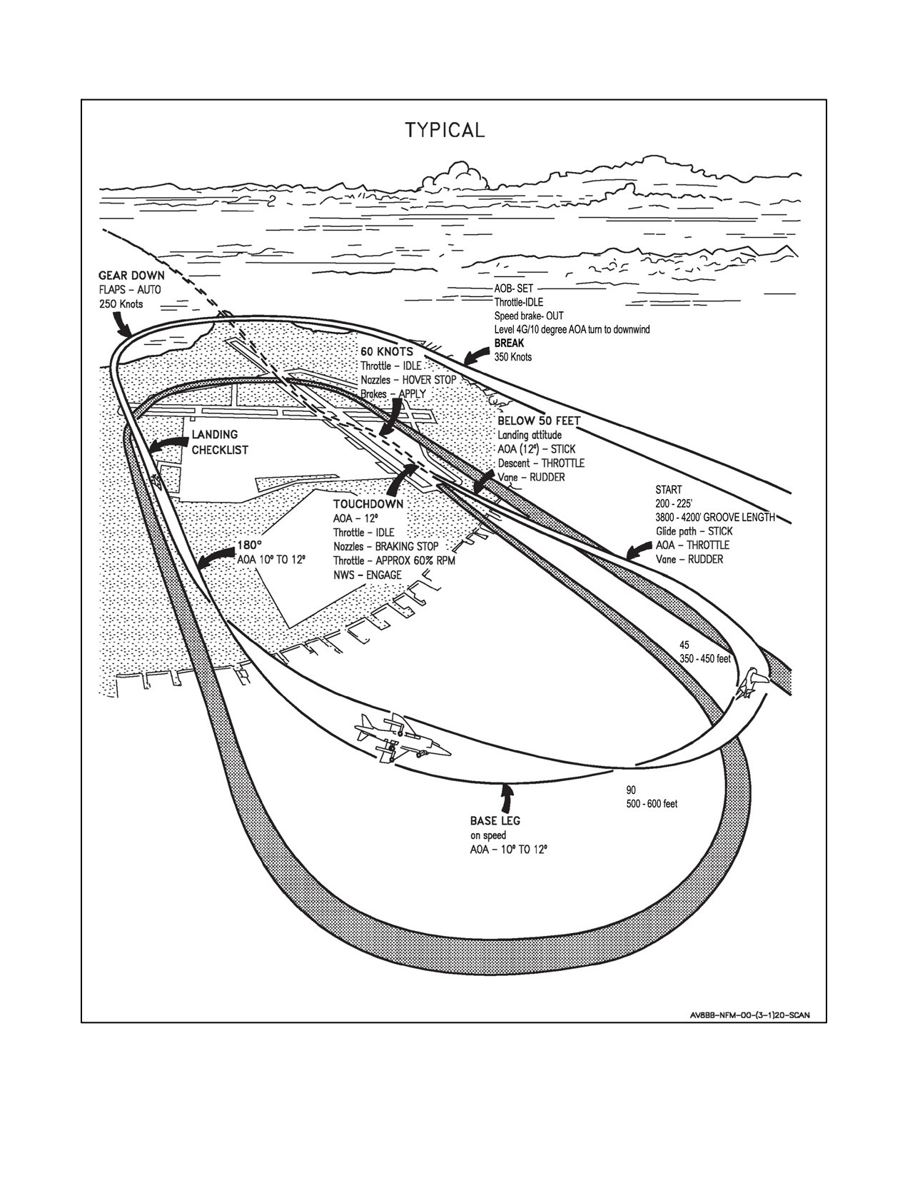
A1-AV8BB--NFM--000
Figure 7-7. Conventional Landing
ORIGINAL
7-62
A1-AV8BB--NFM--000
7.7
POSTFLIGHT
7.7.1 After Landing
When clear of the active runway:
1. Trim — 4° ND.
2. Flaps — CRUISE FOR TAXI.
3. Water — OFF.
4. IFF — HOLD, WAIT 10 SECONDS, THEN AS DESIRED.
5. Master arm switch — OFF.
6. Emergency canopy shattering handle safety pin — INSTALLED (TAV--8B both cockpits).
7. Ground safety control handle — UP (TAV--8B both cockpits).
8. Oxygen switch — OFF.
9. APU — OFF.
10. Landing light — OFF.
When parked:
11.
Nozzles — 0° to 10°.
12.
Parking brake — SET.
13.
ANTISKID switch — ON.
14.
Flap switches — OFF.
15.
Engine life and max JPT — RECORD.
16.
Fatigue life count — RECORD.
17.
MENU, BIT — RECORD FAILURES.
a. If a SAAHS failure code or asterisks is displayed, do a SAAHS BIT before doing the auto BIT. If an SMS
failure code is displayed, select MAINT, SMS, then DISP. Record all failures by scrolling with DISP button.
b. AUTO BIT — PERFORM.
If RDR failure is displayed, select MAINT, RDR then B, O, and A respectively and record all failure codes
(FULL displayed during any of these operations means there are additional failures. Reselecting the
function will scroll through any additional failures).
c. Record other failures to include:
(1) GPS (Loads/errors).
(2) TPOD (DPFL).
(3) ARC--210.
(4) NAVFLIR/ARBS.
7-63
ORIGINAL
A1-AV8BB--NFM--000
(5) IFF.
(6) ASE.
(a) ALQ--164.
(b) ALE--39.
(c) ALR--67.
18. MENU--TPOD--DATA--DPFL — RECORD FAILURES.
a. Hold DPFL until PFL list clears.
b. If PFL list returns, IBIT — PERFORM.
c. Record IBIT failures.
19. Display Computer — CHECK.
a. Set DP switch to PRIM then ALTER, record any failures.
b. Set DP switch to AUTO.
20. INS update — PERFORM/ACCEPT IF APPLICABLE.
Night Attack Aircraft:
21. LST/FLIR switch — AS DESIRED.
Radar Aircraft:
22. FLIR switch — AS DESIRED.
23. RADAR switch — OFF.
All Aircraft:
24. MENU, BIT, MAINT, INS, POST — RECORD INS DATA.
25. TPOD VRS — UNTHREAD. (IF TPOD loaded).
26. TPOD PWR — OFF. (IF TPOD loaded).
27. INS switch — OFF (minimum of 10 seconds before throttle OFF).
28. DDI, HUD, and COMM — AS DESIRED.
29. VRS — LOCAL/UNTHREAD.
30. SDAT — ERASE.
31. ODU — ACPT.
32. Aircraft — SECURE (chock and chain as necessary).
33. Throttle — OFF.
Before engine shutdown, the engine should be idled for a minimum of one minute, if possible, to allow temper-
atures to stabilize.
34. Fuel boost pump switches — NORM.
ORIGINAL
7-64
A1-AV8BB--NFM--000
35. DECS enable switch — OFF.
36. Fuel shutoff handle — OFF.
37. Battery switch — OFF.
38. Personal equipment — DISCONNECT.
Release the two upper Koch connectors from the parachute risers and the two lower Koch connectors from the
lower harness. Disconnect the oxygen/communication leads. Unfasten leg garters. Disconnect anti--g suit.
39. Conduct exterior inspection (Refer to paragraph 7.1.2).
7.7.2 Hot Refueling
The L and R TRANS lights are designed to indicate when the fuel pressure at the inlet to the respective feed tank
has dropped to a point where fuel transfer into the center tank may be insufficient. It provides the pilot with an
indication of fuel pressure, not an indication of fuel level in the fuel tanks. When the fuel tanks are full, it signals
therefueling valveto close, resulting in adrop infuel pressureand illuminationofthecorresponding TRANScaution
light. There are situations, though, when the illumination of a TRANS caution light does not correspond with the
fuel tanks being full. A more accurate indication of fuel levels in the tanks is the LEFT and RIGHT full advisory lights
located on theleft sidewindshield arch. Thefuel high thermistor that is used to determinewhen to close therefueling
valve is same one that illuminates the RIGHT or LEFT full advisory lights. These lights are designed specifically
to indicate full levels in their respective feed group. If a refueling valve fails to close during hot refueling, the fuel
pressure will not drop, and the TRANS caution light will not illuminate to indicate to the pilot that the tanks are full.
This could result in the tanks become overfilled and fuel to stream from the fuel vent mast. With the A/R probe switch
in the OUT position, and the RIGHT and LEFT full advisory lights are activated.
1. Aircraft — CHECKED FOR HOT BRAKES AND UNEXPENDED ORDNANCE.
2. All emitters — SECURED (TCN, RAD ALT, BCN, IFF, AWLS) OR EMCON SELECTED.
3. Nozzles — 10°.
4. Form Lts — OFF.
5. OBOGS — OFF.
6. RAM AIR — SELECTED.
If equipped with an air refueling probe:
7. A/R switch — OUT.
If not equipped with an air refueling probe:
8. A/R switch — IN OR OUT (NOT IN PRESS).
9. Cockpit configuration:
Note
On TAV--8B the seat status, safe or armed, must be the same for both
cockpits.
If Seat armed:
a. Canopy — CLOSED.
7-65
ORIGINAL
A1-AV8BB--NFM--000
10. Pilot strapped--in.
If Seat safe:
a. Canopy — AS DESIRED.
b. Straps — AS DESIRED.
11.
Fuel Load — AS DESIRED (ensure balanced).
LEFT full advisory light (IFR probe) or L TRANS light (no IFR probe) — signal for shutoff (1
FINGER
SIGNAL).
RIGHT full advisory light (IFR probe) or R TRANS light (no IFR probe) — signal for shutoff (2
FINGER
SIGNAL).
12.
After Hot Refueling adjust items in steps 2 to 8 as required.
7.8
RAPID REARM
Note
D Only like stores are authorized for re--loading.
D If hung weapons are present or any weapon failure exists, stop rapid rearm
and use standard rearming procedures. Complete the following checklist to
prepare the aircraft and aircraft systems for hot rearming.
1.
IFF — HOLD, WAIT 10 SECONDS, THEN OFF.
2.
ALQ--164 — OFF.
3.
ALR--67 — OFF.
4.
RADAR — OFF.
5.
FLIR — OFF.
6.
RADALT — OFF.
7.
DMT — OFF.
8.
APU — OFF.
9.
TPOD — OFF.
10.
Master Arm — OFF.
11.
MENU — STRS. Verify no WPN FAIL.
12.
MENU — BIT. Verify no SMS BIT codes.
13.
MENU--BIT--SMSFF — Verify no WPN FAIL or HUNG indications.
14.
INS — GND ALGN.
Note
Do not turn INS off. The alignment will hold through the rapid rearm
procedure. Ordnance crews will ground the aircraft and establish
communications with the pilot with hand--and--arm signals or via ground
communication input directly to the aircraft. Once the above checklist is
complete communicate via “thumbs--up” hand--and--arm signal or voice
communications that the aircraft is ready for rapid rearm.
ORIGINAL
7-66
A1-AV8BB--NFM--000
When the ordnance crew signals:
15. GEN — OFF (approximately 20 to 30 seconds).
On aircraft without AFC 392, Digital Engine Control Unit power is now provided by the battery. Monitor battery
voltage ensuring it remains greater than 16--volts. If any engine anomaly occurs, execute Emergency Engine
Shutdown procedures.
Note
Thegeneratormustbeofflinefor15to20secondsinorderforstoresstation
controllers to clear all electrical charge. The ordnance crew will install
cartridges in the BRU--36.
When the ordnance crew signals:
16. GEN — ON.
17. MENU--STRS — Verify weapon loadout is correct.
If weapon loadout is correct:
18. Signal to ordnance crew via “thumbs--up” hand--and--arm signal or voice communication indicating weapon
loadout is correct.
If weapon loadout is incorrect:
19.
Signal to ordnance crew via “thumbs--down” hand--and--arm signal or voice communication indicating
weapon loadout is incorrect.
20.
Troubleshoot.
Reset aircraft systems.
21.
IFF — ON.
22.
ALQ--164 — ON.
23.
ALR--67 — ON.
24.
RADAR — ON.
Note
RADAR sets will have to be reprogrammed.
25.
FLIR — ON.
26.
RADALT — ON.
27.
DMT — ON.
28.
APU — ON (if desired).
29.
TPOD — ON.
30.
INS — IFA or NAV.
31.
LASER CODE — PROGRAM AS DESIRED.
7-67
ORIGINAL
A1-AV8BB--NFM--000
7.9
SCRAMBLE OPERATION
The aircraft is designed to operate from forward sites in close proximity to the FEBA (forward edge of the battle area)
with minimum support. Normally such sites are dispersed, camouflaged and operated in such manner that each
aircraft is an independent entity except for control through communications. With the short reaction time available
due to the proximity to the FEBA and the STO capability, many formerly airborne evolutions, such as on--call close
air support or CAP, are conducted with the aircraft on the ground at a forward site. Before assuming the directed Ready
Condition, the pilot should perform normal preflight, start, post start and pre--takeoff checks. Shut down the engine
and set the parking brake. Dependent upon the prescribed ready condition the pilot may then be required to remain
strapped in the cockpit or may un--strap and remain in close proximity to the aircraft. If un--strapped, pull ground
safety control handle up. The battery switch position is dependent upon the radio monitoring requirement.
7.9.1 Scramble Interior Check
1. Harness — FASTEN (if unfastened).
2. Canopy — CLOSE AND LOCK.
3. Ground safety control handle — DOWN.
7.9.2 Scramble Engine Start
1. Battery switch — BATT.
2. Fuel shutoff handle — ON.
3. DECS enable switch — ON.
4. Engine start switch — ENG ST.
5. Throttle — IDLE.
6. Warning and caution lights — TEST.
7. Inertial navigation system — ALIGN.
Radar Aircraft:
8. RADAR switch — OPR.
All Aircraft:
9. Inertial navigation system — NAV/IFA AS REQUIRED.
10. FLAPS — ON/RESET.
11. Parking brake — RELEASE.
ORIGINAL
7-68
A1-AV8BB--NFM--000
CHAPTER 8
Shipboard Procedures
8.1
GENERAL SHIPBOARD PROCEDURES
Refer to NAVAIR 00--80T--111.
8-1/(8-2 blank)
ORIGINAL

A1-AV8BB--NFM--000
CHAPTER 9
Special Procedures
9.1
FORMATION FLIGHT
The following sections describe the parameters for each standard formation, procedures for maintaining position, and
the execution of formation flight. Figure 9-1 is a summary of all standard formations characterizing each formation’s
attributes with respect to environment, maneuverability, mutual support, and application. Refer to NTTP
3--22.1--AV--8B for more specifics on the tactical employment of each formation.
FORMATION
ENVIRONMENT
MANEUVERABILITY
VISUAL MUTUAL
STANDARD APPLICATION
SUPPORT
Section Formations
Instrument Departures and
Approaches
IMC or VMC
Parade
Limited
None
Break
Day or Night
En route IMC
En route VMC
VMC
Cruise
Average
Limited
Formation rendezvous
Day or Night
Administrative holding
En route VMC
Defensive Combat
Day VMC
Fair
Excellent
Medium to High Threat (A/S)
Spread
Battle Break
En route VMC
Offensive Combat
Day VMC
Good
Good
Spread
Medium to High Threat (A/A)
En route VMC
Fighter Wing
Day VMC
Excellent
Limited
Tactical Holding
En route VMC (night)
Day or Night
Deployed Echelon
Excellent
Limited
Administrative execution (night)
VMC
Tactical execution (night)
Division Formations
Administrative execution
Division Parade
Day VMC
Limited
None
Break
Balanced Parade
Day VMC
Limited
None
Administrative execution
Fingertip
Day IMC
Limited
None
IMC penetration
En route VMC
Cruise
Day VMC
Fair
Limited
Administrative holding
Deployed Echelon
Night
Good
Limited
Night execution
Wedge
Day VMC
Good
Fair
Low altitude tactical execution
Box/Offset Box
Day VMC
Excellent
Excellent
Low altitude tactical execution
Fluid Four
Day VMC
Excellent
Good
Medium altitude tactical execution
Wall
Day VMC
Limited
Excellent
Medium altitude tactical execution
Figure
9-1.
Standard Formations Summary
9-1
ORIGINAL
A1-AV8BB--NFM--000
9.1.1 Section Administrative Formations
9.1.1.1 Parade
The parameters for section parade are: a bearing line extended from lead’s aileron and flap hinge lines, maintaining
lateral distance by superimposing the outrigger landing gear wheel on the center of the fuselage avionics panel (door
60L or R), and stepped down by aligning the wingtip and bottom of the fuselage. See Figure 9-2.
9.1.1.1.1 Turns
Parade turns are either VFR parade turns or instrument flight rules (IFR) parade turns.
9.1.1.1.2 VFR Parade Turns
For VFR parade turns, if the lead rolls away from the wingman, the wingman maintains parade step down position
and rolls about his axis and matches leads roll rate and ultimate AOB. When using this technique, the lead aircraft’s
intake obscures the leader’s head making it difficult to exchange hand--and--arm signals. If the lead rolls into the
wingman, the wingman maintains parade bearing line, lateral distance, and relative step down position cues and rolls
about the lead’s axis. This requires a slight power reduction to maintain position during turn execution to facilitate
slight altitude and radius--of--turn reductions.
9.1.1.1.3 IFR Parade Turns
For IFR parade turns, the wingman maintains parade bearing line, lateral distance, and relative step down position
cues rolling about lead’s axis either with a slight increase in altitude on turns away or slight decrease in altitude on
turns into the wingman. Roll--rate should be slower to account for IMC limited visibility and so as not to induce
vertigo. At night, execute IFR parade turns.
9.1.1.1.4 Cross--under
Perform cross--unders by reducing power slightly to go sucked on the bearing line, while simultaneously descending
to achieveadequatevertical clearancefrom lead’s aircraft and jet wash. Ensuring aminimum nose--to--tail separation
of one--half aircraft length, cross under lead’s aircraft in a “U” shaped maneuver to a low and sucked position on the
otherside. Halfway through themaneuvertheaircraft fuselages should bealigned noseto tail. Onceon theotherside,
add power to climb and move forward to parade position. When flying in division fingertip, it is necessary for the
aircraft on the opposite side to make room for the crossing aircraft in division parade position.
9.1.1.1.5 Lead Change
The flight leader passes the lead to his wingman via voice communication or hand and arm signals. After
acknowledging receipt of the lead, the new dash 2 (the former lead aircraft) increases lateral separation slightly then
reduces power to move back to the parade bearing line. Power is then added to stop the aft movement and close back
to parade position.
9.1.1.2 Cruise
The parameters for section cruise are: a 120 degree cone aft of lead’s 3/9 line, a minimum nose--to--tail separation
of one aircraft length, and a slightly stepped--up position to enable the flight leader to keep sight of the wingman.
See Figure 9-3. To establish cruise formation, the flight lead uses a hand signal of a clenched fist with the thumb out
and the right arm alternating across each shoulder or stating, “CLEARED TO CRUISE.” When maneuvering, the
wingman maintains position in the cone inside or outside the lead’s turn radius to manage proper nose--to--tail
separation. Maintaining position in the cone is critical to ensuring collision avoidance if the lead maneuvers abruptly.
9.1.2 Section Tactical Formations
9.1.2.1 Combat Spread
There are two types of combat spread: defensive combat spread and offensive combat spread.
9.1.2.1.1 Defensive Combat Spread
The parameters for defensive combat spread are: abeam, 0.7 to 1.0 NM, and an altitude split of 1,000 to 3,000 feet
(above or below lead’s aircraft). If flying below 1,000 feet AGL, maintain co--altitude with the lead aircraft. See
Figure 9-4.
ORIGINAL
9-2
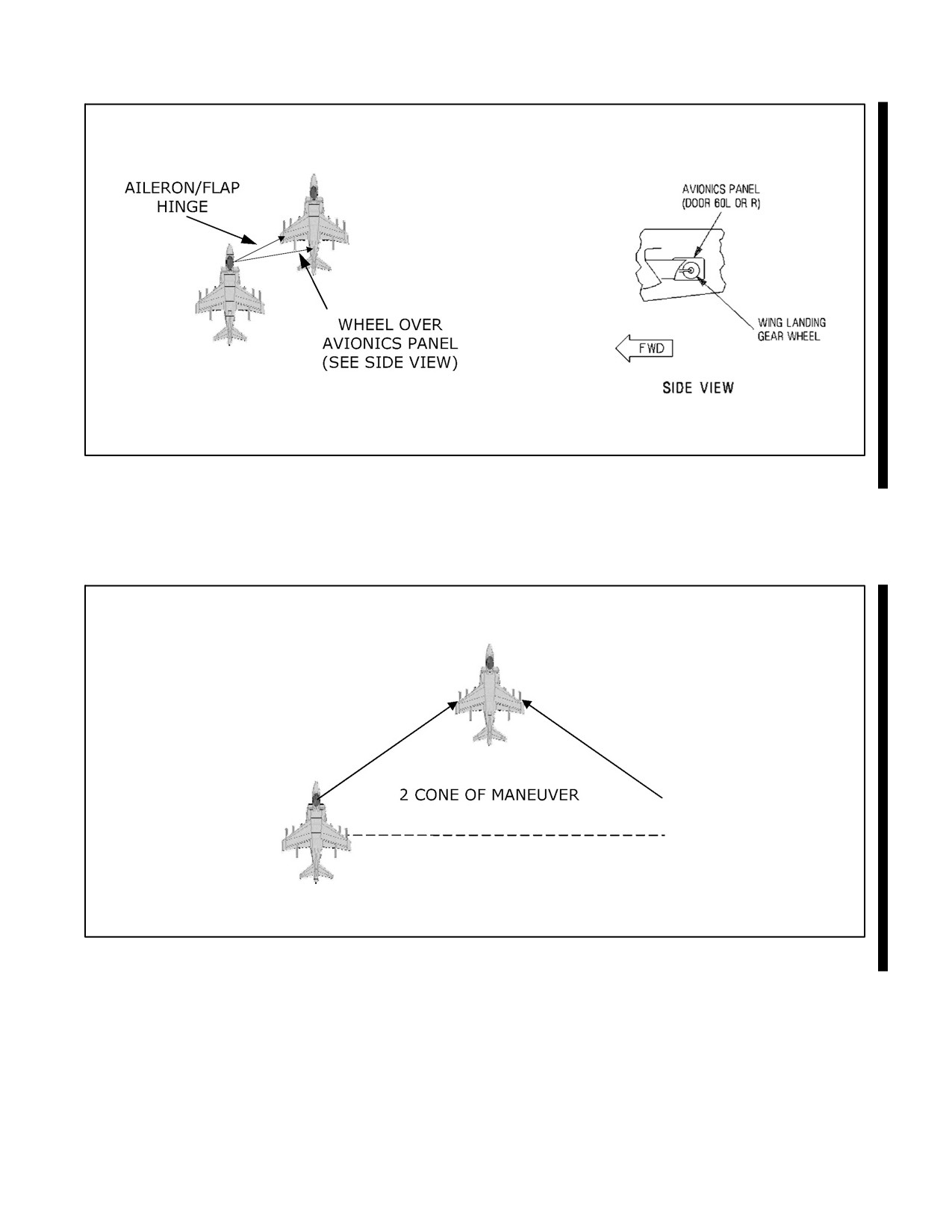
A1-AV8BB--NFM--000
Figure 9-2. Section Parade
Figure 9-3. Section Cruise
9-3
ORIGINAL
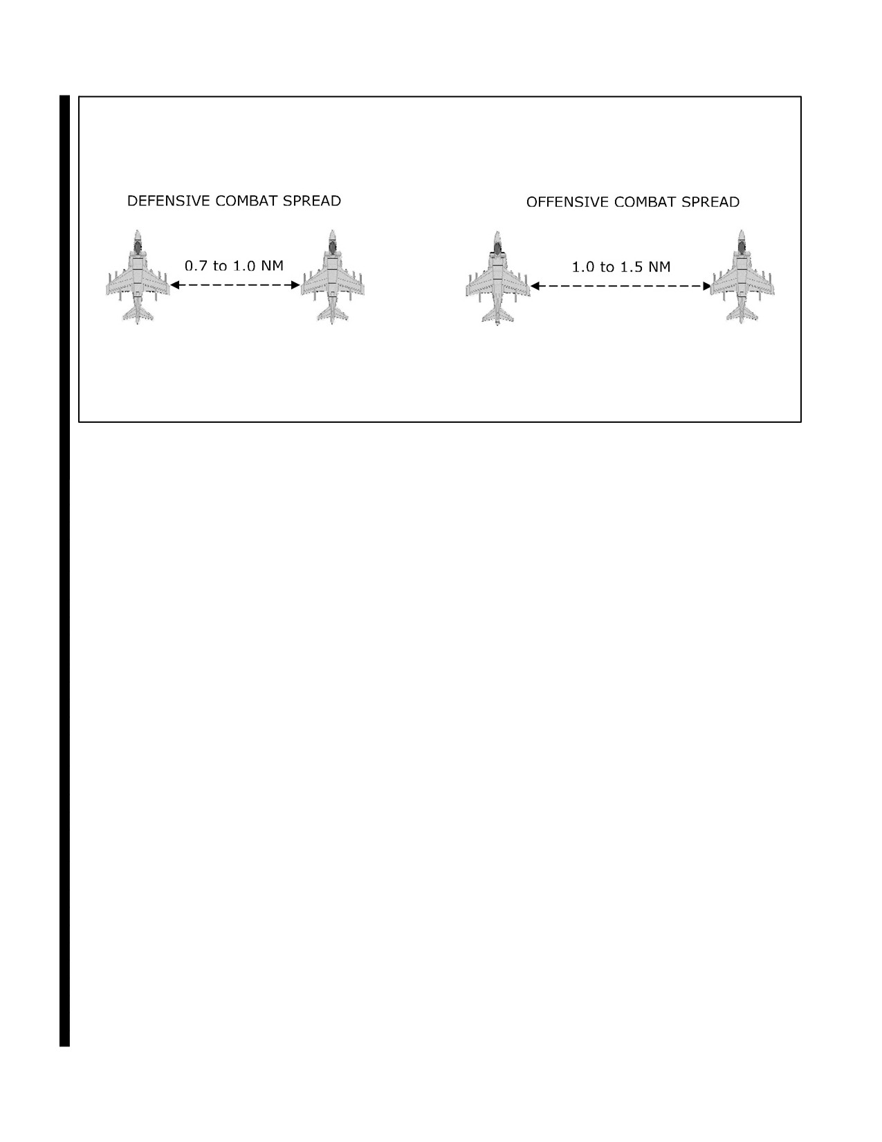
A1-AV8BB--NFM--000
Figure 9-4. Combat Spread
9.1.2.1.2 Offensive Combat Spread
The parameters for offensive combat spread are: abeam, 1.0 to 1.5 NM, and an altitude split of 3,000 to 5,000 feet
(above or below lead’s aircraft). If flying below 1,000 feet AGL, maintain co--altitude with the lead aircraft. See
Figure 9-4.
9.1.2.1.3 Combat Spread Execution
The flight lead initiates combat spread with a hand signal of an outward pushing motion with the hand and arm, with
the palm outboard or transmitting “TAKE DEFENSIVE (OFFENSIVE) COMBAT SPREAD ON THE RIGHT
(LEFT).” The wingman will take a cut away from lead, add full power, and fly to the briefed position (high or low).
To close the formation to cruise or parade, lead porpoises the aircraft or transmits, “CLEARED TO PARADE (OR
CRUISE).” The wingman will take a slight turn into lead and place him on or slightly above the horizon (on the
horizon if the flight is below 1,000 feet) and rejoin. A slight power addition may be necessary. Perform a
CV(Circling)/Running rendezvous and watch for lateral closure since aspect will be minimal. Continuously reference
the A/A TACAN distance measuring equipment (DME) throughout the maneuver.
9.1.2.1.4 Maintaining Combat Spread Position
If sucked, use a combination of geometry (e.g., a shackle turn) and power to regain position. If acute, take a cut away
to decrease downrange travel and reduce power as required. Reset the proper abeam distance after achieving the
proper abeam bearing line.
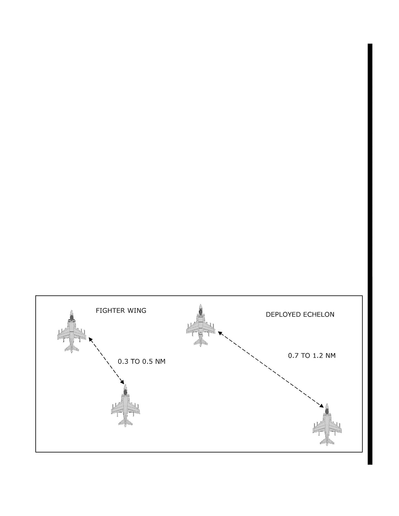
9.1.2.2 Fighter Wing
The parameters for fighter wing are: a bearing line 30 to 60 degrees aft of lead’s 3/9 line, 2,000 to 3,000 feet
nose--to--tail separation (0.3 to 0.5 NM slant range), and an altitudedifferential of1,000 to 3,000 feet (aboveorbelow
lead’s aircraft). If flying below 1,000 feet AGL, maintain co--altitude. See Figure 9-5. While maneuvering, wing will
maintain position off lead by using turn circle geometry. As lead turns, wing will maneuver to get on lead’s turn circle,
maintain position until the turn is just about complete, then float to the opposite side, resetting fighter wing. Turns
into the wingman will cause him to delay the turn until lead is about to cross wing’s nose. Wing will then roll in the
direction of turn, start the pull, place lead on the canopy rail, and fly on lead’s turn circle. Approaching the desired
heading, wing will float the turn to the outside and reset the fighter wing position. Turns away from wing require wing
to turn when lead turns. Wing will pull to lead’s turn circle and maintain position until approaching the desired
ORIGINAL
9-4
A1-AV8BB--NFM--000
heading. As lead rolls out on the new heading, wing will continue to pull, temporarily go belly up, and reset the fighter
wing position on the inside of the turn.
9.1.2.3 Deployed Echelon
This formation is similar to fighter wing but has increased nose--to--tail separation to facilitate increased mission
crosscheck time for the wingman by slightly reducing position keeping tasking. However, it is critical to maintain
the proper bearing line to prevent sliding to a trail position. It is extremely difficult to perceive closure, especially
at night, from a trail position. The parameters for deployed echelon are: a bearing line 60 to 70 degrees aft of lead’s
3/9 line, 0.7 to 1.2 NM slant range, and an altitude split of 1,000 feet above or below lead’s altitude. If flying below
1,000 feet AGL, maintain co--altitude. See Figure 9-5.
9.1.3 Section Tactical Maneuvering
This section details the procedures for maneuvering a formation other than parade or cruise. All turns are hard turns
(full--power, energy--sustaining turns) unless otherwise briefed. When maneuvering at altitudes above approximately
20,000 feet, at high gross weights, or high drag indices, turns are at full power and constant airspeed due to the
reduction of lift and g available.
9.1.3.1 Formation Altitude Splits
The altitude differential between aircraft in a formation is a balance between environmental considerations, threat
lookout/avoidance, and the airspace available. The primary de--confliction method for a visual formation is visual.
If at any time a visual formation is not maintained (e.g., times when both aircraft are working cockpit systems (TPOD,
RADAR, etc.)) a briefed altitude contract will be maintained for de--confliction. Traditionally, AV--8B formations
have been flown with 1,000 foot altitude intervals with the wingmen in a stepped up position. This is not required
if visual de--confliction is maintained. In some formations, (e.g., fighter wing), 1,000 feet of altitude split makes it
difficult for the wingman to maintain sight of lead in a stepped up position (500 feet of separation, level, or stepped
down may be preferred). Additionally, in combat, rarely is 3,000 to 4,000 feet of airspace available for unimpeded
use by a division. Flight leads will likely have to modify the altitude de--confliction to account for this. Wingman
will have to adjust by flying extremely disciplined formations to maintain visual separation and/or reduced lateral
and vertical separation. Use of the Automatic Flight Control (AFC) and altitude hold is encouraged to ease cockpit
workload.
Figure 9-5. Fighter Wing and Deployed Echelon
9-5
ORIGINAL
A1-AV8BB--NFM--000
9.1.3.2 COMM--OUT Maneuvering
COMM--OUT turns are the standard with a known (briefed) route or holding pattern. Called turns are the standard
when off the briefed route. COMM--OUT maneuvering procedures are:
1. The flight lead may use a double microphone click to get the wingman’s attention.
2. When observing a wing flash, wing turns into lead.
3. Always assume the turn is a 90 degree tac--turn unless:
a. Lead immediately turns into wing (cross turn or shackle turn).
(1) If cross turn, lead will continue the turn.
(2) If shackle turn, lead will roll out after approximately 45 degrees.
b. Lead immediately turns away (hook turn).
c. Lead turns after wing has turned 30 to 60 degrees (nav turn).
4. Lead turns into Wing without a wing--flash (assume tac--turn).
a. Lead rolls out after only 30 to 60 degrees of heading change (nav turn).
5. The only COMM--OUT turn not performed is a Hook Turn into the wingman as there is no effective
COMM--OUT method to signal this.
9.1.3.3 De--confliction
Wingmen are always responsible for de--confliction from the lead’s aircraft. For maneuvering at medium altitudes,
maintain the established trend (e.g., if stacked low, de--conflict low). For maneuvering below 1,000 feet AGL, the
wingman will always de--conflict above the lead aircraft.
9.1.3.4 Check Turn
A check turn is used to change course up to 30 degrees. Check turns are unique in that they are the only turns which
do not provide a built--in formation geometry fix. That is, check turns will put the formation out of position. Lead
initiates check turns by transmitting, “RAZOR 11, CHECK--LEFT/RIGHT.” Lead may also include the number of
degrees to turn or the new reference heading such as “RAZOR 11, CHECK LEFT REFERENCE 270.” COMM--OUT
check turns are not signaled, lead will simply turn to the new heading. Independent of how the turn is signaled, the
wingman must be proactive to minimize formation geometry misalignment by making immediate corrections to
reduce the time out of position.
9.1.3.4.1 Check Turns into Wingman
Due to a smaller turn radius, the wingman has a shorter distance to travel thus driving the geometry acute. Counter
this with an aggressive S--Turn. Perform the S--Turn in the horizontal or the oblique plane to slow downrange travel
and/or convert airspeed to altitude. As lead rolls out and the aircraft drops back to bearing, lower the nose to regain
airspeed then adjust the abeam distance if required. Avoid the tendency to simply reduce power to adjust geometry.
This causes the wingman to become slow and typically fall to sucked position unless the acceleration is properly
timed.
9.1.3.4.2 Check Turns Away from Wingman
Due to a larger turn radius, the wingman has a longer distance to travel thus driving the geometry sucked. Maneuver
to decrease turn radius and/or lower the nose to increase airspeed. Once on bearing, smoothly raise the nose and bleed
off excess airspeed to regain altitude. Avoid anticipating bearing line or pulling up too aggressively, thereby
stagnating or falling backed sucked. Avoid gaining excessive airspeed causing acute geometry or forcing a rapid
pull--up.
ORIGINAL
9-6
A1-AV8BB--NFM--000
9.1.3.5 Nav--Turn
Use a nav--turn to change course 30 to 60 degrees. The lead initiates the nav--turn by transmitting, “RAZOR 11,
NAV--LEFT/RIGHT.” COMM--OUT nav--turns are initiated into the wingman when lead initiates a turn into the
wingman. COMM--OUT nav--turns are initiated away from the wingman with a wing flash.
9.1.3.5.1 Nav Turns Into Wingman
For turns into the wingman, lead turns 30 to 60 degrees and rolls out. The wingman then executes a small turn to fly
70 to 80 degrees tolead’s flightpath andpass aheadoflead.It ismoreimportantto passin frontofleadthan toachieve
the 70 to 80 degrees track crossing angle. As the wingman crosses lead’s flight path, reverse course to arrive in combat
spread on the opposite side.
9.1.3.5.2 Nav Turns Away From Wingman
For turns away from the wingman, the maneuvering roles are exactly the opposite of a nav--turn into the wingman.
That is, after lead communicates to initiate a nav--turn, the wingman turns into lead 30 to 60 degrees. The wingman
stops turning when reaching the assigned heading or when lead initiates a turn into the wingman. As the lead crosses
the wingman’s flight path, lead reverses course to arrive in combat spread on the opposite side. The wingman is then
responsible for adjusting formation geometry to combat spread.
9.1.3.6 Tac--Turn
Use a tac--turn to change course 60 to 120 degrees. The lead initiates a tac--turn by transmitting, “RAZOR 11,
TAC--LEFT/RIGHT.” COMM--OUT tac--turns are initiated when lead turns or executes a wing--flash.
9.1.3.6.1 Tac--Turn Into Wingman
For tac--turns into the wingman, lead turns first. If executing a COMM--OUT tac--turn, lead simply starts turning
towards the wingman. If lead turns more than 60 degrees, this indicates to the wingman that a tac--turn is likely
desired, not a nav--turn (refer to rules above). The wingman delays turning until lead’s intakes are visible (i.e., lead
is in purepursuit). Thewingman then executes ahard turn to match lead’s heading, observes lead roll out aftergreater
than 60 degrees but less than 120 degrees of turn, and arrives on the opposite side of the formation.
9.1.3.6.2 Tac--Turn Away From Wingman
For tac--turns away from the wingman, the wingman executes a hard turn as soon as lead signals for a turn (voice
communication or wing flash). Unless indicating a specific heading, the wingman will turn for 90--degrees. After lead
rolls out on the new heading, the wingman is then responsible to adjust formation geometry.
9.1.3.7 Hook Turn
Use a hook turn to change course by 120 to 240 degrees. The hook turn is initiated when lead transmits, “RAZOR
11 HOOK--LEFT/RIGHT.” COMM--OUT hook--turns are only executed away from the wingman, never into the
wingman and are signaled only with a wing--flash. Lead turns away from the wingman as soon as the wingman starts
turning. To execute a hook turn, both aircraft perform a hard turn in the direction specified. It is critical to fly a
predictable hard turn to ensure proper formation geometry on roll--out. If lead and the wingman have differing turn
performance, the wingman will arrive acute or sucked and/or with too much or too little lateral separation.
9.1.3.7.1 Hook Turn Into Wingman
Always signal hook turns into the wingman via voice communication. As the turn begins, the wingman will lose sight
oflead. As theturn ends, thelead will losesight ofthewingman. It is critical that as theturn ends, the wingman either
quickly regains sight and establishes de--confliction orimmediately reports “BLIND”and begins to scan altitudeand
A/A TACAN DME while searching for lead. If the wingman reports “BLIND”, the lead must immediately report
status as well and positively establish de--confliction via altitude and headings.
9-7
ORIGINAL
A1-AV8BB--NFM--000
9.1.3.7.2 Hook Turns Away From Wingman
Hook turns away from the wingman are the mirror image of hook turns into the wingman. For this turn, as the section
is through 90 degrees of turn, the wingman is ideally at the lead’s 6 o’clock position. If the top of lead’s aircraft is
visible, lead is through more of the turn than the wingman. This will drive the wingman sucked and too close on
roll--out. Momentarily increase g and then re--establish a hard turn. Take caution to avoid pulling into buffet and/or
bleeding off maneuvering speed thus resulting in sucked geometry. Conversely, if the bottom of lead’s aircraft is
visible, lead is through less turn than the wingman. This drives the wingman acute and too far away on roll--out.
Momentarily reduce g to ease the turn and then re--establish a hard turn. Take caution to not float the turn into lead’s
airspace while simultaneously going belly up.
9.1.3.8 Cross Turn
Use cross turns to reverse course 180 degrees and provide excellent visual mutual support throughout the maneuver.
Lead initiates the cross turn by transmitting, “RAZOR 11, CROSS TURN.” The COMM--OUT Cross Turn is initiated
by a wing flash and is initially similar to a shackle. Once the wingman begins turning into lead, lead immediately
turns into the wingman. Instead of rolling out as in a shackle, the lead continues to turn thus signaling the wingman
to continue until course reversal. The wingman de--conflicts above and slightly outside of lead. Since the turn is
predicated on both aircraft making identical turns, any basic air work deviations affect the resultant formation
geometry.
As lateral separation decreases at cross turn initiation, the resultant lateral separation increases at turn completion.
This is exacerbated by higher altitudes, drag indices, and gross weights. If initiating a cross turn from defensive
combat spread, the wingman continues to turn past the final reference heading for 10 to 30 degrees to drive back to
the proper abeam distance.
9.1.3.9 Shackle
Use a shackle to readjust formation geometry, establish desired target area geometry, and/or delay momentarily to
correct route timing. The lead initiates a shackle by transmitting, “RAZOR 11, SHACKLE.” Lead initiates
COMM--OUT shackles by using a wing--flash to get the wingman to turn. Lead then turns as soon as the wingman
begins turning. Both aircraft roll--out after 45 degree of turn, cross paths, and then reverse to arrive in combat spread
on the original heading.
If using a shackle to adjust formation geometry, the amount of turn each aircraft executes varies to ensure proper
resultant formation geometry. If the formation is wide, then the procedures remain the same except that both aircraft
will not extend past the merge for the same length of time it took to get there. Generally, three seconds is a good
starting time for the delay. This time will vary somewhat depending on offensive or defensive combat spread and
the speed of the aircraft. If the wingman is acute or sucked, the geometry becomes more dynamic. The acute aircraft
turns more than 45 degrees, slowing downrange travel. He must not turn too farto avoid going sucked in theprocess.
In general, the acute jet should not cross the sucked jet’s flight path at an angle of greater than 90 degrees. On the
other hand, the sucked jet needs to increase its downrange travel to catch up with the acute jet. In extreme cases, the
sucked jet may just check turn to ensure he crosses the other aircraft’s flight path and drive into position. Remember,
the wingman has an altitude contract and is responsible for de--confliction.
9.1.4 Division Administrative Formations
9.1.4.1 Division Parade
The parameters for division parade are essentially the same as section parade except three or four aircraft are now
in parade formation. It is incumbent on the flight lead to minimize aggressive maneuvering (no greater than 30 deg
AOB) in this formation as the “whip” action makes it difficult for dash 3 and 4 to maintain a proper bearing line.
Gradual changes in airspeed are also recommended to ensure formation integrity. Pilots should delay transitioning
to division parade formation for as long as possible (e.g., after the final turn to the runway initial is complete).
Division parade should not be used for extended IMC penetration due to the “whip” effect and reduced visibility. See
Figure 9-6.
ORIGINAL
9-8
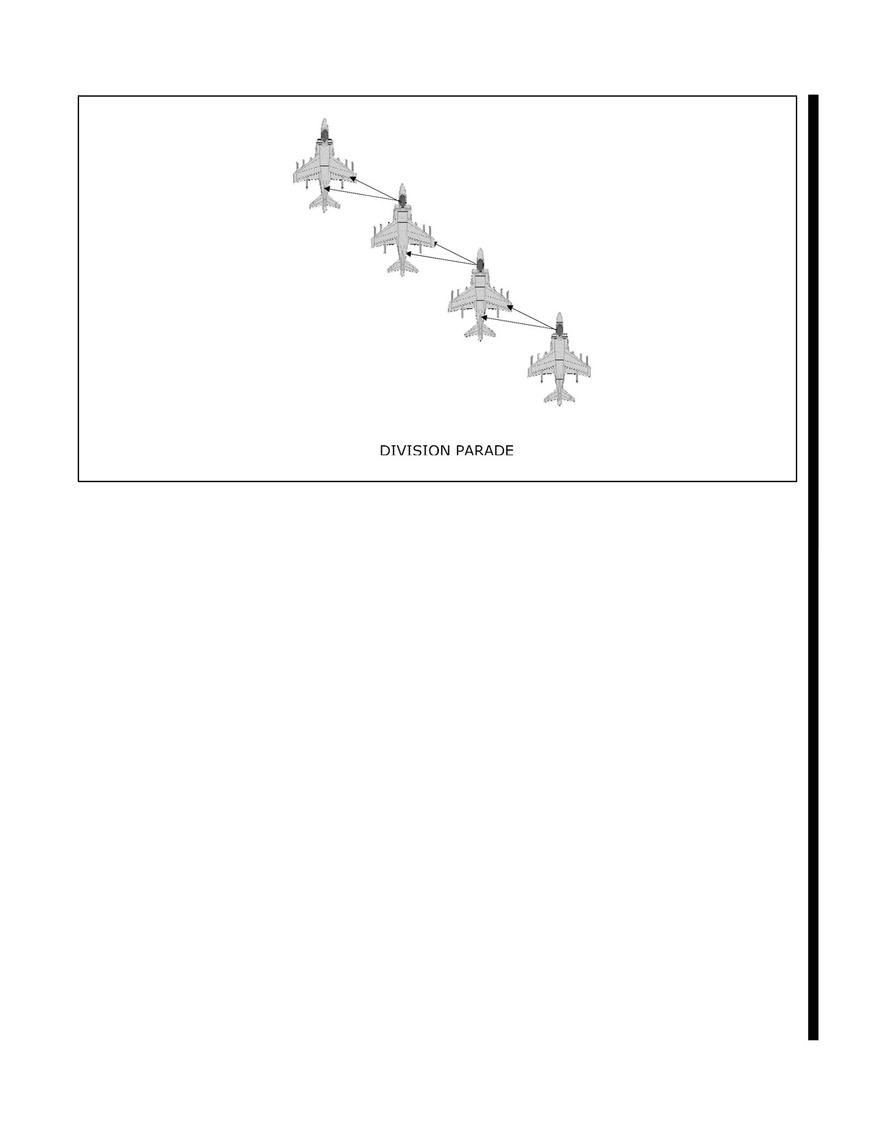
A1-AV8BB--NFM--000
Figure 9-6. Division Parade
9.1.4.2 Balanced Parade
The parameters for balanced parade are dash 2 and 4 maintain section parade on their respective leads. Then, dash
3 increases lateral separation on the lead aircraft until the outrigger landing gear wheel is in the center of thefuselage
avionics panel (door 60L or R) of dash 2; and stepped down by aligning the wingtip and bottom of the fuselage. This
leaves enough space between lead and dash 3 for dash 2 to cross under to form division parade. See Figure 9-6. Dash
2 positions on the opposite side of the lead aircraft from dash 3. Section cross--unders are performed by dash 3 in the
same manner as described in paragraph 9.1.1.2 with dash 4 executing a simultaneous cross--under on dash 3.
9.1.4.3 Fingertip
When entering IMC conditions with a three or four plane formation, the preferred option is to divide the flight into
a section and a single (3--ship) or into two sections (4--ship) in RADAR trail. If this is not feasible, the lead directs
the flight to assume fingertip formation. To execute this formation, start in balanced parade and have dash 3 move
up into parade on the lead. See Figure 9-7.
9.1.4.4 Division Cruise
The parameters for division cruise are dash 3 maintains fighter wing off the lead, dash 2 balances opposite dash 3
in section cruise on lead. Dash 4 maintains section cruise on dash 3. See Figure 9-8.
9.1.4.5 Administrative 3--Ship Division Formations
For administrative purposes, 3--ship formations simply drop the dash 4 aircraft from each one of the formations listed
above.
9.1.5 Division Tactical Formations
9.1.5.1 Deployed Echelon
The parameters for division deployed echelon are: all aircraft on a bearing line 45 degrees aft of lead’s 3/9 line. Dash
2 is 0.7 to 1.2 NM from lead. Dash 3 is from 1.2 to 2.5 NM from lead. Dash 4 is 0.7 to 1.2 NM from Dash 3. Dash
3 maintains an altitude split of level to 1,000 feet above or below lead. See Figure 9-9.
9-9
ORIGINAL
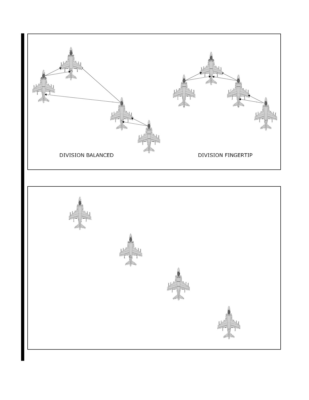
A1-AV8BB--NFM--000
Figure 9-7. Division Fingertip and Balanced Parade
Figure 9-8. Division Cruise
ORIGINAL
9-10
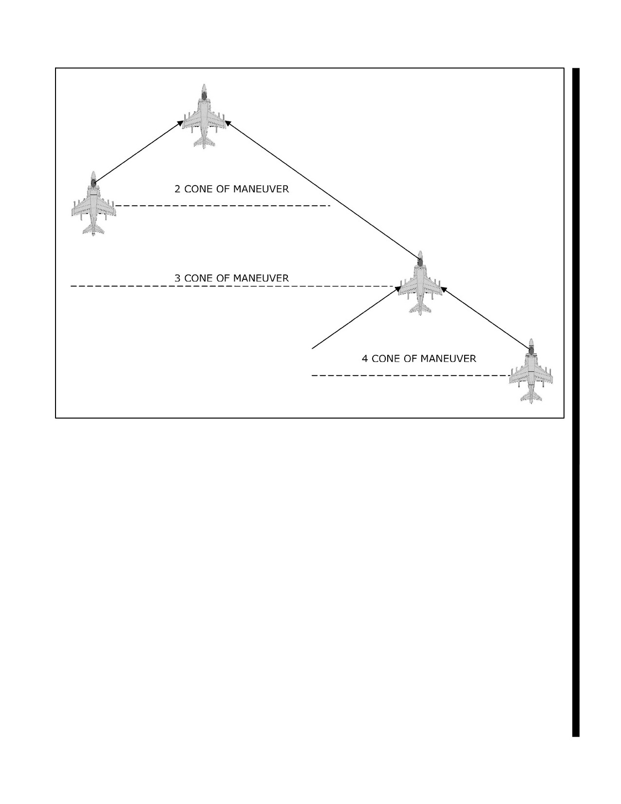
A1-AV8BB--NFM--000
Figure 9-9. Deployed Echelon
9.1.5.2 Fluid Four
The parameters for fluid four are dash 3 flies defensive combat spread on lead, dash 2 and dash 4 fly fighter wing
on their respective leads, and maintain an altitude split of 1,000 to 3,000 feet. If flying below 1,000 feet AGL, the
formation is co--altitude. The division leader will establish the de--confliction plan based on mission requirements.
For example, for air--to--surface missions, the second section may be stacked high or for air--to--air missions, the
second section may be stacked low. While maneuvering, lead and dash 3 execute combat spread maneuvering
procedures while dash 2 and dash 4 maintain fighter wing positions on their respective lead. The second section must
provide positive de--confliction from lead’s section or broadcast its intentions. All turns should be level unless
de--confliction dictates otherwise. The wingmen need only to maneuver their aircraft with respect to their lead’s
aircraft as though they are in section. All section combat spread turns can be performed from fluid four. See Figure
9-10.
9.1.5.3 Division Box
The parameters for division box are: lead and dash 2 fly defensive combat spread, dash 3 and dash 4 fly defensive
combat spread between 1.0 and 2.5 NM behind the lead section, maintaining an altitude split of 1,000 to 3,000 feet.
If flying below 1,000 feet AGL, maintain co--altitude with the lead section. For an “offset box” the trail section offsets
3,000 feet left or right from the lead section. See Figures 9-11 and 9-12.
9.1.5.4 Wedge
The parameters for division wedge are: dash 2 maintains fighter wing while dash 3 and dash 4 fly defensive combat
spread between 1.0 and 2.5 NM aft of the lead section maintaining an altitude split of 1,000 to 3,000 feet. If flying
below 1,000 feet AGL, maintain co--altitude with the lead section. See Figure 9-13.
9-11
ORIGINAL
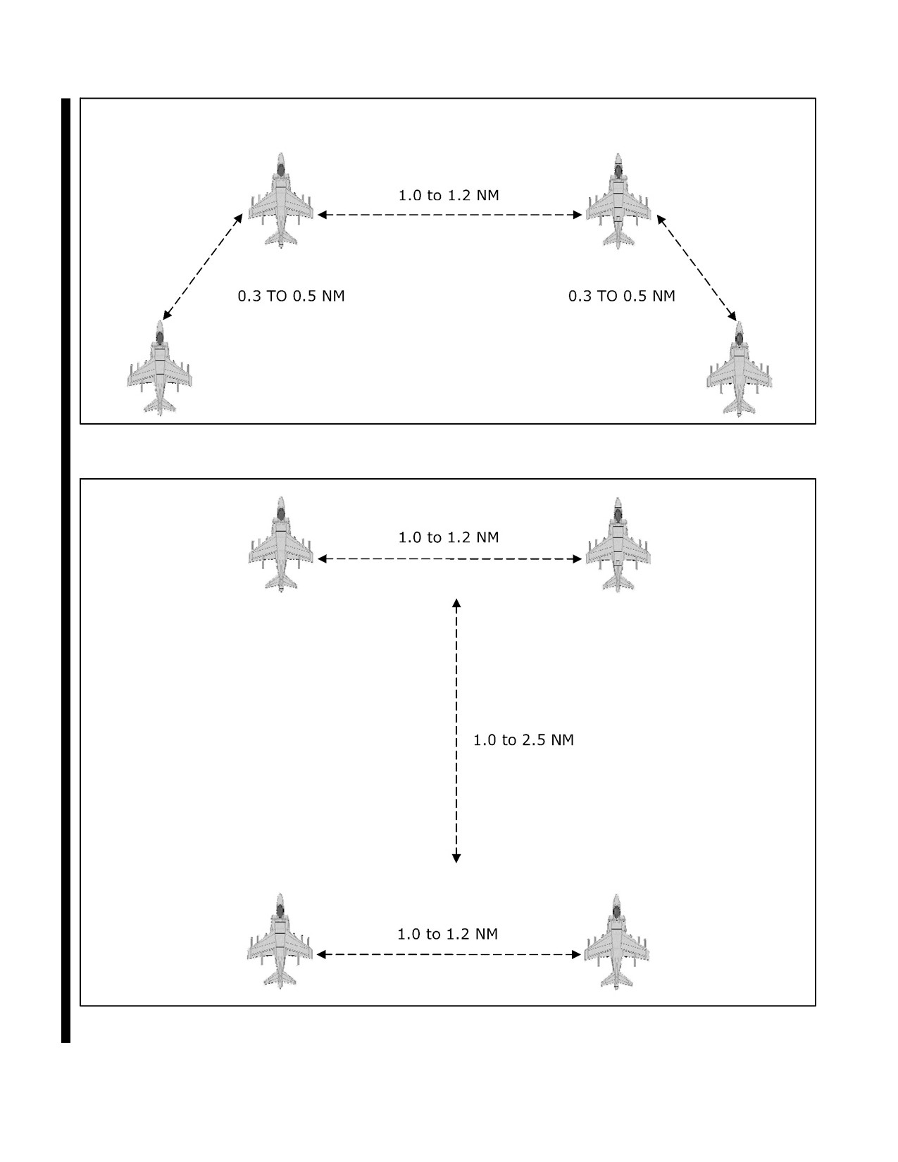
A1-AV8BB--NFM--000
Figure 9-10. Fluid Four
Figure 9-11. Division Box
ORIGINAL
9-12
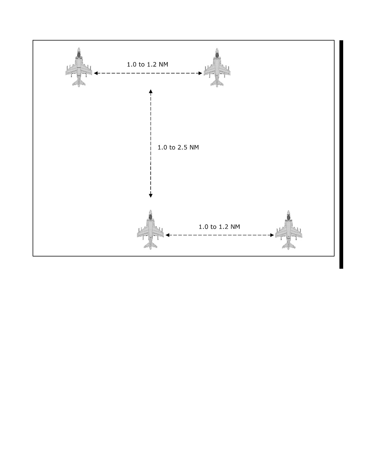
A1-AV8BB--NFM--000
Figure 9-12. Division Offset Box
9-13
ORIGINAL
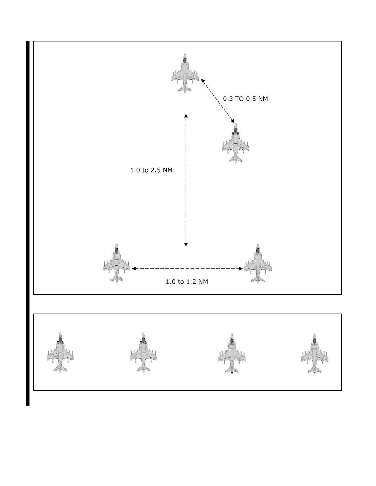
A1-AV8BB--NFM--000
Figure 9-13. Division Wedge
Figure 9-14. Division Wall
ORIGINAL
9-14

A1-AV8BB--NFM--000
9.1.5.5 Wall
The parameters for division wall are dash 3 maintains defensive (or offensive) combat spread on lead, dash 2 and dash
4 maintain defensive (or offensive) combat spread on their respective flight leads. See Figure 9-14.
9.1.5.6 Tactical 3--Ship Division Formations
Figure 9-15 shows three ship tactical formation options.
FORMATION
OPTION
Deployed Echelon
“Ghost” Dash 2
Fluid Four
“Ghost” Dash 4
Box/Offset Box
Fly Offset Box with “Ghost” Dash 2
Wedge
“Ghost” Dash 2
Wall
“Ghost” Dash 4
Figure 9-15. Recommended Division 3 Ship Formation Options
9.1.6 Division Maneuvering
9.1.6.1 Fluid Four Maneuvering
Maneuvering in fluid four consists of combat spread section maneuvering between lead and dash 3. The wingmen
maintain a fighter wing position on their respective leads throughout the maneuvering. For continued mutual support,
after maneuvering has ceased, the wingmen resume fluid four ensuring they look through their respective leads into
therest ofthedivision. All calls areinitiated by thedivision lead to dash 3. Forexample: “RAZOR 21 FLIGHT, TAC
LEFT”. The division then executes a tacturn. Dash 2 and 4 remain silent throughout all maneuvers in this formation.
Transitions from fluid four to wedge/box may be accomplished however the flight lead dictates. Lead initiates the
transition by stating, “RAZOR 21 FLIGHT, ASSUME WEDGE/BOX”. Transitions are either executed by the
division lead with a 90° turn away from dash 3 orby dash 3 with a 90°turn into the division lead. Iflead pumps away
from the division, dash 3 then follows after the appropriate time delay to flow in trail. Dash 4 then assumes combat
spread position on dash 3. If dash 3 pumps into the division lead, after the appropriate time delay, he resumes the
original heading. Out of the turn, dash 4 assumes combat spread position. To transition from wedge/box back into
fluid four, the division lead initiates a 90° turn left/right followed by a reversal back to original heading in order to
expedite the transition. Both dash 2 and dash 4 then assume fighter wing on their respective leads to resume the fluid
four formation.
9.1.6.2 Box Maneuvering
All calls are initiated by lead to the wingman. For example: “RAZOR 21, TAC--RIGHT,” and they execute the
tac--turn. Dash 3 follows lead’s cues, restates the same intentions to his section, and initiates at the same point as the
lead section. This will typically occur anywhere from 4 to 12 seconds after lead’s call (“RAZOR 23, TAC--RIGHT”)
based on nose--to--tail distance between the first and second section. All turns can be performed from division
box/offset box.
9.1.6.3 Wedge Maneuvering
Assume any turns in division wedge to be 90 degrees unless called. Lead may give a reference heading or degrees
of turn for all other turns. In that case, lead may say, “RAZOR 21, HOOK RIGHT, REFERENCE 210.” Dash 2 will
remain silent since he is flying fighter wing. Dash 3 initiates the required turn after the appropriate delay with,
“RAZOR 23, HOOK--RIGHT (or CROSS TURN).”
9.1.6.4 Wall Maneuvering
Turns in division wall are limited to pumps, tac--turns, and hook turns.
9-15
ORIGINAL
A1-AV8BB--NFM--000
9.1.7 Formation Rendezvous
9.1.7.1 Running Rendezvous
A running rendezvous is a method of joining on a non--maneuvering aircraft from the rear quarter. The wingman
should know the leader’s airspeed to avoid an overshoot. The wingman should maneuverto achievea parallel course
with a moderate amount of lateral separation (< 500 feet). The visual cue for this is placing the lead aircraft between
the edge of the HUD glass and the canopy bow. The wingman simultaneously establishes a moderate rate of closure
on thelead (no morethan 50 knots). Sinceclosureis difficult to detect when approaching from therear, avoid placing
the velocity vector on lead’s aircraft and closely monitor the A/A TACAN DME. As the wingman approaches the
parade bearing line, reduce speed so as to arrive on bearing with no more than 25 knots of closure. The aircraft is then
flown up the bearing line to an appropriate formation position. If attempting to join a flight prior to entering IMC,
theflight lead should carefullyconsidertheceiling andflight clearancerequirements. Adjusttherendezvousairspeed
if necessary to expedite the join--up. If unable to safely join a flight underneath the weather, transition to a RADAR
trail departure. If conducting a running rendezvous in division, the flight lead should thoroughly brief the desired
side for each aircraft’s join--up if joining in any formation other than division parade.
In the event that closure is not under control during the final phase of a running rendezvous, execute an overrun with
the following procedures:
1. Lower the nose to create vertical separation.
2. Turn away from lead to increase lateral separation.
3. Throttle — IDLE.
4. Speedbrake — OUT.
5. Transmit “RAZOR 12, OVERRUN”.
6. Once slowed, allow the lead to pass by, intercept the bearing line, and complete the rendezvous.
9.1.7.2 CV (Circling) Rendezvous
A CV (circling) rendezvous is a method of joining up on a turning aircraft from the rear quarter. Again, the wingman
should know the leader’s airspeed. Although it is possible to rendezvous co--airspeed the circling rendezvous can be
expedited by using approximately 25 knots of closure when on the bearing line. The wingman maneuvers to pure
pursuit and holds this flight path until he enters lead’s turn circle. At this point, determine position relative to the
leader’s bearing line. If forward of the bearing line, go to lag pursuit by leveling wings or making a slight turn away
from lead. This maneuver should place the aircraft on or aft of the bearing line. If on the bearing line, turn to align
fuselages then readjust to the bearing. If aft of the bearing line, increase the rate of turn to fly toward the bearing line
while simultaneously aligning fuselages. Once achieving the bearing line, adjust fuselage alignment by placing the
lead aircraft just forward of the junction of the canopy bow and the lower edge of the windscreen. The wingman will
normally join to parade on the outside of the turn. This requires taking step down at one aircraft length of separation,
then executing a normal cross--under to IFR parade. If conducting this rendezvous as a division, wingmen must
maintain situational awareness of not only the lead aircraft but other aircraft conducting the join--up. If one aircraft
isslowtojoin,itmayrequiretheotheraircrafttostagnateonbearinglineuntiltheslow aircraftcompletes thejoin--up.
In the event that closure is not under control during the final phase of a circling rendezvous, execute an underrun with
the following procedures:
1. Lower the nose to create vertical separation.
2. Level wings to pass behind the lead aircraft.
3. Throttle — IDLE.
4. Speedbrake — OUT.
ORIGINAL
9-16
A1-AV8BB--NFM--000
5. Transmit “RAZOR 12, UNDERRUN”.
6. Oncestabilizedontheoutsideandcleared bylead, turninsidetoreestablish thefinal portionoftherendezvous.
9.1.7.3 Tacan Rendezvous
A tacan rendezvous is a method of using a tacan navigation aid to join aircraft that are not in visual contact. The
wingman must know the leader’s altitude. The leader flies to the briefed tacan fix, either inbound or outbound, and
establishes a constant angle of bank turn to the left at the pre--briefed altitude and airspeed. The joining aircraft
establishes altitude separation and then flies to the pre--briefed fix while visually searching for lead. To enhance the
probability of visual acquisition, each pilot should communicate his current position on the circle. The fix is point
one, 90° of turn is point two, 180° of turn is point three and 270° of turn is point four. Once the wingman is visual,
perform the appropriate rendezvous.
9.1.7.4 Rendezvous Technique
The use of nozzles to slow closure during a rendezvous is an acceptable technique but can lead to additional pilot
workload and the possibility of inadvertently leaving the nozzles out of the full aft position.
Inadvertently leaving the nozzles near the hover or braking stop position
can be mistaken for engine failure and result in aircraft damage and/or loss
of aircraft control. The following are indications of this condition:
—Lack of forward thrust despite full power.
—Inability to maintain level flight despite full power.
—15 Second light.
—Extreme sensitivity in the pitch axis.
—Duct pressure above 3 PSI.
—Nozzle indicator on EPI not AFT.
—RPM above 109% (combat disabled), or above 111% (combat enabled).
9.1.7.5 Night Unaided Considerations
Unaided rendezvous at night pose significantly more risk of midair collision due to the lack of closure cues and lack
ofvisual acuity. Strictadherencetoclosureratesis required,no morethan 25knots intrail and15 knotson thebearing
line. Because the aircraft will not be visible to the naked eye until in close when the closing aircraft’s own
anti--collision light begins to illuminate the lead aircraft, the light triangle should be used to approximate an
acceptable bearing line for re--join. The light triangle is defined as the upper anti--collision light positioned 1/3 of
the distance aft of the port/starboard position light and 2/3 of the distance forward of the aft position light. When on
bearing line, continuous monitoring of airspeed (closure) and the light triangle (bearing) as well as a disciplined scan
of proper altitude in the HUD is required to complete a safe join.
9.1.7.6 Night Aided Considerations
While night vision goggles improve the visual acuity at night, closure is difficult to assess without angular rates due
to the lack of depth perception. The night--time light triangle is still a valuable tool to use during a CV rendezvous;
however, thepilot will begin to seetheaircraft soonerthan an in closeposition. Oncethelead aircraft is seen visually,
a visual scan of the appropriate bearing and altitude should be commenced. Night--time closure rates should still be
controlled, no more than 25 knots in trail and 15 knots on bearing, in order to complete a safe join.
9-17
ORIGINAL W/IC 38
A1-AV8BB--NFM--000
9.2
AIR REFUELING
Note
Before air refueling operations, each pilot shall be familiar with the
NATOPS Air Refueling Manual and the flight characteristics of the air
refueling probe. See Flight Characteristics, Chapter 11. Air refueling is
authorized for the single seat model only.
Aerial refueling operations are authorized with the tankers listed in Figure 9-16. All tanker limits apply. Use of all
other tankers is prohibited. Aerial refueling operations are authorized in all cleared loading configurations. Ferry
loading CG must be maintained forward of 14.5 percent mean aerodynamic cord (MAC) by keeping the maximum
water quantity below 250 pounds.
9.2.1 Before Plug--in
The air refueling checklist should be completed prior to plug--in.
1. Master arm switch — OFF.
2. A/R switch — OUT (READY light ON).
3. Probe light — AS DESIRED.
Note
The L and R TRANS lights may illuminate after tank depressurization but
internal fuel will still be available to the center tanks by siphoning action.
CONTINUED
ORIGINAL W/IC 38
9-18
A1-AV8BB--NFM--000
PLATFORM
MINIMUM
MAXIMUM
MINIMUM
MAXIMUM
AIRSPEED
AIRSPEED
ALTITUDE
ALTITUDE
USAF
220 KIAS (USAF)
300 KIAS/0.86
Greater of 5,000’
35,000’ MSL
KC--135R1,2,3,4
IMN
MSL or 1,500’
French AF
240 KIAS (FAF)
(most restrictive)
AGL
KC--135R1,2,3,4
Spanish B707
230 KIAS
300
KIAS
1,500’ AGL6
35,000’ MSL
Italian B707
(Spanish5/Italian)
Australian B707
250 KIAS
(Australian)
Omega B707
230 KIAS
300
KIAS
Greater of 5,000’
35,000’ MSL7
MSL or 1,500’
AGL
Omega KDC--1011
200 KIAS
290
KIAS
15,000 MSL
30,000 MSL
US/Spanish
210 KIAS
250
KIAS
1,500’ AGL
20,000’ MSL
KC--130
US KC--130J
190 KIAS
250
KIAS
1,000’ AGL
30,000’ MSL
Canadian
210 KIAS
250
KIAS
1,500’ AGL
15,000’ MSL
CC--130T
UK TriStar
230 KIAS
300
KIAS
1,500’ AGL
35,000’ MSL
(K Mk 1,
KC Mk 1)8
UK VC 10
260 KIAS
300
KIAS
1,500’ AGL
30,000’ MSL
(K Mk 2, K Mk 3,
K Mk 4)9
US S--3B
200 KIAS
275
KIAS
1,500’ AGL
25,000’ MSL
US KC--10
200 KIAS
290
KIAS
15,000’ MSL
30,000’ MSL
US F/A--18 E/F
230 KIAS6
250 KIAS10
12,500’ MSL6
17,500’ MSL6
Notes:
1. AR from boom drogue adapter not authorized. Refer to ATP--56.
2. Tanking position high and inboard relative to the MPRS tankers outboard engine may result in the receiver engine
rolling back or flaming out.
3. Lateral stick and trim inputs are required to counter the receiver aircraft tendency to roll toward the tanker.
4. While flying at the approach position (20 feet aft of drogue), small lateral trim inputs may be required to counter a
tendency to roll toward the tanker. Deviations inboard and outboard may require additional lateral stick inputs.
Deviations of more than 10 feet high can result in a strong sideslip (on right tanker wing, full left ball). Flight buffet is a
good indication to reposition down with respect to the tanker.
5. Optimum airspeed for tanker is 275 KIAS or 0.78 IMN, whichever is less.
6. Refueling below 10,000 feet requires special authorization from the RAAF.
7. Airspeeds between 250 and 300 KIAS are recommended above 30,000 feet MSL.
8. Use of tanker high pressure pumps not authorized.
9. Use of tanker high pressure pumps not authorized on centerline system.
10. AV--8B flying qualities may degrade rapidly outside of the F/A--18E/F refueling airspeed and altitude limits.
11. Maximum closure 3 KTS due to probe limit loads.
Figure 9-16. Authorized AR Platforms
9-18a (b Blank)
W/IC 38
A1-AV8BB--NFM--000
4. Airspeed — 190 to 300 KNOTS.
5. Angle--of--attack — 13° MAXIMUM.
6. Flaps — CRUISE.
STOL flaps may be used to maintain AOA below 13°. Use of AUTO flaps is prohibited prior to contact with
drogue basket.
Uncommanded programming of the flaps greater than 25° with nozzles less
than 20° will cause a severe nose down pitch rate. The extreme attitudes
coupled with the negative g’s of up to --2.5, as experienced by the pilot, will
be extremely disorienting and make cockpit functions difficult to perform.
A combination of full aft stick and rotation of the nozzles to an angle greater
than 40° are required to arrest this condition.
7. AFC — ENGAGE (if desired), Reduces workload.
8. Visor — DOWN.
9. Radar — SILENT.
9.2.2 Refueling Technique
Note
The following procedures, as applied to tanker operation, refer only to
single drogue refuelers.
Refueling altitudes and airspeeds are dictated by receiver and/or tanker characteristics and operational needs,
consistent with the tanker’s performance and refueling capabilities. This, generally, covers a practical spectrum from
the deck to 35,000 feet and 190 to 300 knots.
9.2.3 Approach
Once cleared to commence an approach, refueling checklists completed, assume a position 10 to 15 feet in trail of
the drogue with the refueling probe in line in both the horizontal and vertical reference planes. Trim the aircraft in
this stabilized approach position and ensure that the tanker’s (amber) ready light is illuminated before attempting an
approach. Select the drogue as the primary reference point on the tanker. Increase power to establish an optimum 3
to 5 knots closure rate on the drogue. It must be emphasized that an excessive closure rate will cause a violent hose
whip following contact and/or increase the danger of structural damage to the aircraft in the event of misalignment
or drogue take--up reel malfunction; whereas, too slow a closure rate results in the pilot fencing with the drogue as
it oscillates in closeproximity to theaircraft’s nose. Small corrections in theapproach phaseareacceptable;however,
if alignment is off in the final phase, it is best to immediately retire to the initial approach position and commence
another approach, compensating for previous misalignment by adjusting the reference point selected on the tanker.
Small lateral corrections with a shoulder probe are made with the rudder, and vertical corrections with the stabilator.
Avoid any corrections about the longitudinal axis since they cause probe displacement in both the lateral and vertical
reference planes.
9.2.4 Missed Approach
If the receiver probe passes forward of the drogue basket without making contact, a missed approach should be
initiated immediately. Also, iftheprobeimpinges on thecanopy lined rim ofthebasket and tips it, a missed approach
9-19
ORIGINAL
A1-AV8BB--NFM--000
should be initiated. A missed approach is executed by reducing power and backing to the rear at an opening rate
commensurate with the optimum 3 to 5 knot closure rate made on an approach. By continuing an approach past the
basket, a pilot might hook his probe over the hose and/or permit the drogue to contact the receiver aircraft fuselage.
Either of the two aforementioned hazards require more skill to calmly unravel the hose and drogue without causing
further damage than to make another approach. If the initial approach position is well in line with the drogue, the
chance of hooking the hose is diminished when last minute corrections are kept to a minimum. After executing a
missed approach, analyze previous misalignment problems and apply positive corrections to preclude a hazardous
tendency to blindly stab at the drogue.
9.2.5 Contact
When the receiver probe engages the basket, it will seat itself into the drogue coupling and a slight ripple will be
evident in the refueling hose. The tanker’s drogue and hose must be pushed forward 3 to 5 feet by the receiver probe
before fuel transfer can be effected. This advanced position is evident by the tanker’s (amber) ready light going out
and the (green) fuel transfer light coming on. When the tanker’s (green) fuel transfer light illuminates the ready light
on the canopy bow goes out. While plugged--in, merely fly a close tail chase formation on the tanker. Although this
tucked--in condition restricts the tanker’s maneuverability, gradual changes involving heading, altitude and/or
airspeed may be made. A sharp lookout doctrine must be maintained due to the precise flying imposed on both the
tanker and receiver pilots. In this respect, the tanker can be assisted by other aircraft in the formation. When the tanks
are full the refueling valves close to stop the flow and the LEFT and RIGHT full advisory lights come on as follows:
With no external tanks - Flashing when the internal wing fuel tanks are full.
With two external tanks - Flashing when the external tanks are full.
With four external tanks - Steady when the inboard external tanks are full and flashing when the outboard external
tanks are full.
Switching from CRUISE flaps to AUTO flaps is authorized after probe engagement with the drogue. Selection of
AUTO flaps should occur after the aircraft is stabilized in the refueling basket and before aircraft angle of attack
increases above 5°. Waiting to initiate the transition from CRUISE to AUTO until the angle of attack has increased
above 5° will cause an abrupt change in flap position, resulting in a more severe pitch attitude change, oscillations,
and possible disconnect from the basket.
CAUTION
Transition from CRUISE flaps to AUTO flaps while tanking may result in
disengagement unless timely power corrections are made to correct
positional trends. If the flap transition results in a sustained pilot--induced
oscillation, execute emergency breakaway procedures. CRUISE or STOL
flaps must be selected before attempting to reconnect to the basket.
9.2.6 Disengagement
Disengagement from a successful contact is accomplished by reducing power and backing out at a 3 to 5--knot
separation rate. Care should be taken to maintain the same relative alignment on the tanker as upon engagement. The
probe will separate from the drogue when the hose reaches full extension. When clear of the drogue, place the A/R
switch to IN. The LEFT and RIGHT full advisory lights go out when the probe is fully retracted or if PRESS is
selected.
9.3
FORWARD OPERATING BASE
A Forward Operating Base (FOB) offers the MAGTF Commander flexibility through quick emplacement and
repositioning of forces, rapid response to battle requirements and enhanced survivability during counterattack.
Doctrinally, a FOB is an airfield used to support tactical operations without establishing full support facilities and
ORIGINAL
9-20
A1-AV8BB--NFM--000
should not be confused with an Expeditionary Air Field (EAF) which is a construction method using AM--2
Aluminum Matting. The base may be used for an extended time period or abandoned as the battle moves and a new
FOB is established. Support from a main operating base is required to provide backup support for a FOB. The basic
requirements for a FOB are secure location, beyond indirect enemy fire but within a combat radius of 15 to 250
nautical miles, and accessible to logistical support lines.
An airfield can be considered a FOB even though the runway dimensions are comparable to a permanent airfield.
It is the absence of full support facilities such as standard airfield lighting, robust air traffic control services, or on
site or robust weather services that determine if Forward Base Operations (FBO) and considerations are appropriate.
Additionally, a FOB may be operating with waivers to standard airfield procedures so that operations can proceed
withoutextensivedelays.Waiverscanincludelightingrequirements,obstructionfreezones,orconcurrentoperations
restrictions (helicopter and fixed wing operations). During recent AV--8B employment in Operation Iraqi Freedom
and Operations Enduring Freedom, VMA squadrons have operated at An Numaniyah, Al Asad Air Base, Kandahar
International, and Bagram Air Base. Each airfield poses unique operating challenges due to variations in airfield
environment and support facilities and capabilities.
9.3.1 Concept of Employment
There are four types of FOBs: main base, air facility, air site, and air point. Categorization is determine by logistic
and maintenance support available, not by size or location. Each type of FOB has potentially unique challenges for
safe execution. A detailed discussion of each is published in MCWP 3--21.1, Aviation Ground Support.
9.3.2 FOB Operations Preparation
Prior to operating from a FOB, a detailed site survey must be completed IAW MAG or Wing SOP by designated
personnel from Operations, Logistics, Safety, and Maintenance Departments. Administration and Intelligence
Departments personnel may be required depending on the objectives of the FOB. The objective of a site survey is
to quantify the availability of support services, identify gaps in services and subsequent potential hazards and
challenges to operations. The endstate of the site survey is to develop Standard Operating Procedures (SOP) for FOB
execution.
9.3.2.1 FOB Site Survey
AFOBsitesurveyshallinclude,but isnot limitedto, inspectingflight planningfacilities, airfieldcondition, andATC
services. As part of the site survey, coordinate with the tenant command that is responsible for maintaining and
operating the facility to obtain a copy of the FOB SOP for detailed review. The objective of a site survey is to
determine what effects the condition of the FOB will have on maintaining tactically sound and safe operations.
9.3.2.1.1 Flight Planning Facilities
Adequate flight planning facilities are crucial for safe, detailed flight planning and execution. Research the
availability of the following flight planning resources: operating area navigation publications, airfield diagram, local
area of operations charts, weather services, and flight planning and preparation work spaces.
9.3.2.1.2 Airfield Inspection
AthoroughinspectionofallaspectsoftheFOBiscritical.Inspecttherunwaysandtaxiwaystodeterminedimensions;
location and types of arresting gear; visual landing aids; distance marker availability and visibility day and night;
condition of the surfaces; clearance from nearest obstacles; presence of FOD removal equipment and procedures; and
condition and layout of parking apron. The focus of this airfield inspection is to determine what effect the airfield
layout will have on Normal and Emergency procedures.
The airfield surface must be sufficiently hard to prevent the aircraft from sinking into the surface. A minimum CBR
(California Bearing Ratio) hardness of 8 to 10 percent at 3 inches below the surface is required for STOs, RVTOs,
RVLs, and SLs from a smooth strip. STOs, RVTOs, RVLs, and SLs from rough surfaces may damage the landing
gear.
9-21
ORIGINAL
A1-AV8BB--NFM--000
Finally, a detailed inspection of the expected landing point is required. In addition to determining suitability, surface
conditions, and durability, determine a precise GPS coordinate and elevation for all intended points of landing to
include airfield centerline at both approach ends and any vertical landing points. Accomplishing this will support
FBO recovery and landing procedures.
9.3.2.1.3 ATC Services
Liaison with all aspects of air traffic control (ATC) services at the airfield to include ground controllers, tower
controllers, Crash--Fire--Rescue, and radar services personnel. Obtain a copy of local course rules procedures.
Determine the availability of instrument approach services. The focus of the ATC services inspection is to determine
if modifications or waivers to FAA and/or OPNAVINST procedures are in place and what effect this will have on
Normal and Emergency procedures.
9.3.2.1.4 Normal and Emergency Procedures Review
Upon completion of the site survey and once a complete understanding of the status of the airfield, ATC services,
and flight planning facilities is achieved, conduct a thorough review of all Normal and Emergency Procedures
delineated in Chapters 7, 13--18 of this manual. These procedures may be modified to support the location of the site,
surrounding obstacles, threat, and terrain.
9.3.2.1.5 Landing Site Supervisor Kit
Compile and maintain a landing sight supervisor (LSS) kit with the following recommended equipment:
Lensatic compass.
Maps.
Colored panels.
Pyrotechnics (red flares and/or red smoke).
NATOPS manual and NATOPS emergency check list.
Flare pistol with red flares.
Goggles and sound suppressors or HST helmet.
Adequate VHF, FM, and UHF communications equipment.
Binoculars.
JMPS Computer.
GPS.
NVGs.
9.3.3 FBO Training
FBO are extremely challenging and pose potentially insidious hazards that are mitigated through a detailed SOP,
thorough pilot training, and standardized execution. Before executing from a FOB, thorough pre--deployment
training is essential. This training should include lectures, simulators and flights. Lectures should include aircraft
and engine handling specifics and Normal, Emergency, and instrument flight procedures germane to the FOB.
Simulator and flight training should replicate the flight conditions of the FOB as much as possibleto includeaircraft
configuration, runway dimensions, weather conditions as well as day, night and instrument flight scenarios.
9.3.4 FBO Execution
Since each FOB is unique, a detailed SOP is required that provides specificprocedures forpreflight, taxiing, takeoff,
recovery, and landing. These procedures should include instrument flight condition considerations and night
ORIGINAL
9-22
A1-AV8BB--NFM--000
procedures. Furthermore, care must be taken during all ground operations to decrease the risk of FOD especially when
operating from an unprepared site. While at the FOB, due attention must be given to individual pilot proficiency and
currency in regard to the specific characteristics of the site.
9.3.4.1 FBO Supervision
DuetothedynamicenvironmentofFBO,havingaLandingSiteSupervisor(LSS)onstationfortakeoffs andlandings
will enhance situational awareness. The primary responsibility of the LSS is akin to a LSO--safe and timely recovery
of aircraft. The LSS can ensure the intended point of landing is satisfactory and support pilots with threat lookout,
Emergency Procedure execution, and airfield support services coordination. The LSS is another Risk Mitigation
resource. Others include Operational Duty Officers (ODO) and Supervisors of Flight (SOF) that can be positioned
in the airfield tower or squadron Operations Department to assist pilots during FOB operations. The LSS will
supervise a mandatory FOD walk and inspection. Additionally, the LSS will ensure visual aids are properly
positioned. The LSS shall check all equipment for serviceability including a communications check with all
applicable agencies and assets. Two--way radio communication between the pilot and the LSS is required.
9.3.4.2 Preflight
A normal preflight should be accomplished with particular attention to the intakes and LPC blades for possible
foreign object damage. Ensure clearance between obstacles and aircraft is adequate for performing post start control
checks. Inspect the immediate area for evidence of FOD.
9.3.4.3 Taxiing
Due to the hazards at a FOB, pilots must follow the taxi director’s signals precisely and taxi at a slow controlled rate.
Theantiskid system should beselected offfortaxiing in confined areas. Completeall requisite pre--takeoffchecklists
IAW the FOB SOP. Five degrees of nozzles and full nose down trim should be utilized, unless in the vicinity of other
turning aircraft. In that case, the nozzles should remain aft.
9.3.4.4 Takeoff
Aircraft performance and ordnance load, as well as FOB variables such as surface, slope, and obstacles, will all
determine which takeoff procedure to use. Every takeoff is considered a maximum performance maneuver and pilots
should enter the 14 degree pitch carats as well as program runway heading, relative wind and obstacles to determine
NRAS and abort capability.
CAUTION
A combination of aircraft gross weight, engine performance, environmen-
tal factors (e.g. temperature) and runway length, may induce an NRAS that
exceeds abort capability. If required, perform a wet STO to ensure either
abort capability is available or, at a minimum, STO speed is only slightly
greater than abort speed. If abort speed is less than wet STO NRAS,
determine modifications to Emergency Procedures that are appropriate for
that particular FOB.
Additionally, arming the ALE--39 to AUTO as part of the takeoff checklist may be necessary in certain tactical
situations.
Note
The 28 Vdc Armament BUS receives power from the Armament Contactor
Relay when the aircraft is weight off wheels and the landing gear handle is
in the up position. Therefore, the ALE--39 will only be available when
landing gear handle is selected up and the aircraft is weight off wheels,
independent of whether the gear is still in transition.
9-23
ORIGINAL
A1-AV8BB--NFM--000
Engine acceleration checks should be conducted on a FOD--free surface to the maximum extent practical. Avoid
positioning theaircraft with theintakes in close proximity to an expansion joint or areaof damaged runway to reduce
the risk of FOD ingestion during acceleration checks. Flaps and duct pressure checks should also be conducted on
a hard, FOD--free surface. Additionally, flap checks can be conducted at idle RPM.
9.3.4.5 CTO and STO Procedures
The following takeoff procedures have proven operationally effective during FBO execution in an effort to reduce
FOD ingestion from damaged runways and/or simultaneous helicopter and jet aircraft use. They are adaptable to fit
either a CTO or STO procedure. For a CTO, the aircraft rotation speed is defined by gross weight at takeoff and is
independentoftemperatureandaltimetersettings.DuringFBOexecutionwithaircraftgrossweightat 31,000pounds
and 12,000 feet of runway available, a CTO with a rotation of approximately 165 KCAS proved effective while
maintaining an abort capability. However, a tailwind will increase KGS faster than KCAS and potentially cause KGS
to exceed the limit for tire speed (180 KGS) before rotation airspeed is reached. Additionally, temperature and
altimeter settings affect a CTO in two ways. First, as temperature increases or altimeter setting decreases, the amount
of takeoff roll required to reach rotational speed will lengthen encroaching upon abort distance requirements. Second,
extremely high outside air temperatures and/or low altimeter settings may cause a slight difference between KCAS
and KGS inducing a rotation airspeed that exceeds the limit for tire speed. These conditions were particularly
exacerbated during the summer months with high ambient air temperatures and low altimeter settings. In these cases
a wet STO was executed with modifed procedures.
To determine the safest procedures, conduct detailed mission planning balancing the following factors:
1. Aircraft gross weight.
2. Forecasted maximum ambient air temperature and minimum altimeter setting.
3. Forecasted wind velocity.
4. Runway length available. Consider the worst case scenario, i.e. runway length remaining for the lead aircraft
if positioning a flight on the runway.
5. Airfield elevation.
6. Maintaining an abort capability.
The following procedures comprise a modified STO affecting the ground roll portion of the takeoff:
1. Position the aircraft so that the aircraft intakes are not directly over an expansion joint, an area of damaged
runway, or an area with FOD present.
2. All aircraft in the flight complete takeoff and acceleration checks as per paragraph 7.3.1 Takeoff Checklist and
report Two/Five finger.
Lead begins to roll and initiates takeoff:
3. NWS Engage.
4. Brakes -- release.
5. Allow aircraft to accelerate while maintaining throttle position at 60 percent RPM.
6. At 30 KGS smoothly advance the throttle to full power.
7. Complete CTO or STO procedure as per paragraph 7.3.2 or 7.3.3 as applicable.
When the next member of the flight recognizes that the preceding aircraft is at full power (exhaust plume and/or
engine noise), initiate takeoff beginning with step 3 above.
ORIGINAL
9-24
A1-AV8BB--NFM--000
9.3.4.6 Recovery/Approach
Although each FOB is unique, sensor and system optimization to assist in maintaining situational awareness
throughout the recovery is essential. The FOB landing environment may be extremely dynamic due to weather,
airfield conditions, obstructions, threat, or concurrent operations with other aircraft, including helicopters. Therefore,
thefollowingprocedureswillensurethatallavailablesystemsandsensorsprovidecueingto thedesired landingpoint
prior to commencing either a VMC or IMC recovery, day or night.
1. Select the waypoint of the intended point of landing determined during the site survey. Box DESG--STP.
2. Scroll a courseline to the runway heading for recovery.
3. TACAN — AS REQUIRED.
Day/night VMC recovery: Air--to--Air TACAN--PROX set per flight brief.
Day/night IMC recovery: TACAN set to airfield channel.
Depending on day/night and/or VMC or IMC recoveries.
4. Sensor Select Switch — right to select NAVFLIR.
or
5. Select HUD projection on right MPCD.
or
6. Select the NAVFLIR in the HUD. Adjust brightness and contrast, as desired.
7. Sensor Select Switch — right to select HUD projection on the NAVFLIR.
Intercept local course rules for VMC or IMC recoveries, such as the overhead, straight--in, whirlpool, TACAN, PAR,
or AWLS, to become established in the landing pattern. Prior to recovery, a LSS can conduct a FOD inspection and
then select a position to observe all portions of the landing pattern.
9.3.5 Landing
Landings at a FOB are performed using the normal procedures for SL, RVL, or VL. The landing checklist will be
completed upon reaching the abeam position. In certain tactical situations, select AUTO on the ALE--39 as part of
the landing checklist may be necessary.
Note
The 28 Vdc Armament BUS receives power from the Armament Contactor
Relay when the aircraft is weight off wheels and the landing gear handle is
in the up position. Therefore, the ALE--39 will only be available when
landing gear handle is selected up and the aircraft is weight off wheels,
independent of whether the gear is still in transition.
The FOB environment may not be as clearly defined as that of a main base exacerbated by inclement weather and/or
night operations. Therefore, the intended point of landing may be lost from view during the approach. Fly a normal
approach utilizing system and sensor cues to reacquire visual contact with the correct landing area. Utilize the
courseline on the moving map, re--attack steering in the HUD, and NAVFLIR during the approach turn and while
rolling out on the final approach course to maintain situational awareness to the intended point of landing. Once on
final, the pilot’s attention should be directed toward acquiring and maintaining visual contact with the landing area
and any obstacles that should be taken into consideration. For a RVL a minimum ground speed of 60 knots is required
for landings on unprepared surfaces. Glideslope and intended point of landing should be selected with reference to
terrain in the approach corridor, landing surface condition and length, and aircraft performance. For a VL, depart the
9-25
ORIGINAL
A1-AV8BB--NFM--000
key using visual cues as necessary to arrive over the landing area at the appropriate altitude to prevent FOD and or
surface damage. Pilot attention must not be allowed to focus on the landing area to the exclusion of sideslip, AOA,
and airspeed. Cross the edge of the pad at 100 feet or above. This height should be increased to a minimum of 150
feet if the pad is on a loose surface, otherwise the ensuing dust cloud will impair the pilot’s view and the jet exhaust
could lift the pad. After a vertical landing, and where space permits, it is good practice to taxi clear of the point of
landing to avoid the possibility of the tires becoming heated by the landing surface.
The following landing procedures have proven operationally effective during FBO execution in an effort to reduce
FOD ingestion from damaged runways and/or simultaneous helicopter and jet aircraft use.
1. Execute an AUTO flaps, FNSL with nozzles at 50° for dry runway conditions. The resultant landing speed
is approximately 140 to 150 KGS.
After touchdown:
2. Rudder pedals -- center prior to engaging the nosewheel steering button.
3. Nozzles -- maintain 50 degrees or increase to hover stop to decrease stopping distance.
4. Flaps -- CRUISE as soon as practical.
Decelerating through 85 KGS:
5. Brakes -- engage with slow steady pressure until pedals are fully depressed. See Figure 13-1 for additional
information.
With braking action verified:
6. Trim -- full nose down.
7. Nozzles -- AFT as soon as practical. Ensure nozzles are aft prior to slowing to less than 60 KGS.
8. Brakes -- maintain full application until safe taxi speed. Minimize theuse ofPNB but do not allow theaircraft
to depart the prepared surface or run over the departure end gear because of a failure to apply PNB.
9.3.6 Night Operations
Night operations are permitted from a FOB only if adequate approach and landing environment lighting, either visible
or IR lighting, or visual cues are available providing lateral and directional cues during all phases of approach to
landing. Additionally, securing or dimming landing environment lighting may be effective to prevent NVG blooming
and increase NVG acuity.
9.3.6.1 Takeoff
No changes in takeoff technique are needed for night operations. If a VTO is carried out with limited lighting cues,
it is important that the attitude and heading needed for the transition are stabilized before the transition is started and
the lighting cues are left behind.
9.3.6.2 Landing
When making a VL or RVL at night with restricted lighting cues, there is a tendency to establish the hover at lower
heights than during daylight. This could lead to damage of the landing area and its surroundings. The use of the
landing lights or specially designed ground light cues is mandatory. For vertical landings, do not descend below 150
feet AGL without approval from the LSS.
9.3.6.3 Visual Aides
There are no fixed rules for laying out visual aids. The LSS may use colored panels, barrels or lights to provide line--up
and touchdown cues. At night aircraft will not descend below 150 feet AGL until cleared by the LSS. Sites for night
operations shall have sufficient lighting to provide lateral and directional cues.
ORIGINAL
9-26
A1-AV8BB--NFM--000
9.4
NIGHT VISION DEVICES
D Maneuvering above 3g with the AN/AVS--9 in the up--locked (not in use
but on helmet) position is prohibited.
D When g--loaded in the up--locked position, goggles have slammed down
and departed from the helmet in both centrifuge testing and flight incidents.
D Increased risk of injury is probable when ejecting with NVDs on the
helmet.
9.4.1 AV--8B
The use of AN/AVS--9 NVDs is authorized in the AV--8B.
9.4.2 TAV--8B
The use of AN/AVS--9 NVDs is authorized in TAV--8Bs with AFCs 416, 442, 451, and 455.
9-27/(9-28 blank)
ORIGINAL
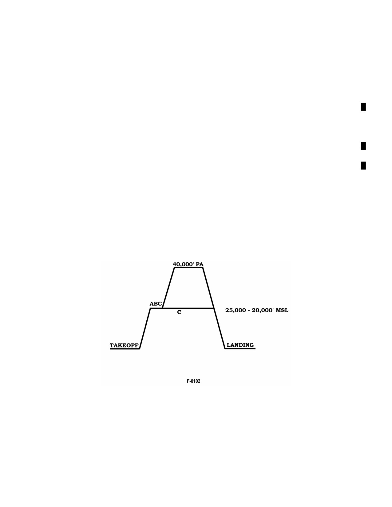
A1-AV8BB--NFM--000
CHAPTER 10
Functional Checkflight Procedures
10.1
GENERAL PROCEDURES
Requirements for Functional Checkflight (FCF) are listed in COMNAVAIRFORINST 4790.2 Series and will be
performed using the applicable Functional Checkflight Checklist. This section contains a detailed description of the
checkflight requirements, sequenced in the order in which they will be performed. The checkflight personnel will
familiarize themselves with these requirements prior to the flight. NATOPS procedures will apply during the entire
checkflight. Only those pilots designated in writing by the Squadron Commanding Officer shall perform squadron
checkflights. Checkflight procedures will be in accordance with the current edition of COMNAVAIRFORINST
4790.2. Minimum crew required for TAV--8B FCF will be one qualified FCF pilot.
PilotswhoperformFCFsshallbequalifiedinaccordancewithOPNAVINST3710.7(NOTAL)andthismanual.They
shall be given a thorough briefing, coordinated by maintenance control, through the use of appropriate Quality
Assurance (QA) work center personnel. This briefing shall describe the maintenance performed, the requirements
for that particular flight, the expected results, and corrective emergency action to be taken if required.
At the discretion of the CO, FCFs may be flown in combination with operational flights, provided the operational
portion is not conducted until the FCF requirements have been completed and entered on the FCF checklist.
Items contained in the FCF requirements are coded. This coding is intended to assist the FCF pilot in determining
which items pertain to thevarious conditions requiring checkflights. Perform theflight profileand applicablechecks
in accordance with the following checkflight conditions:
A. At the completion of aircraft rework and all calendar inspections.
B. After the installation of an engine, engine fuel control, or any FMU components (DECUs are excluded).
C. When fixed or movable flight surfaces, or flight control system components have been installed, reinstalled,
adjusted or rerigged and improper adjustment or replacement of such components could cause an unsafe operating
condition. This is a composite profile for a multitude of aircraft systems. Individual steps may be omitted based on
the nature of the maintenance performed if that individual system is not affected (i.e., a nozzle trim check is not
required for the replacement of the rudder and vice versa; a 450 knot trim check is not required for a nozzle trim
adjustment).
10-1
ORIGINAL
A1-AV8BB--NFM--000
Note
The presence of external stores may aggravate or invalidate some of the
flight checks in the FCF profile.
A new Functional Checkflight Checklist, A1--AV8BB--NFM--700, need not be initiated in flights which are a
continuation of the original FCF. Items not completed shall be noted on the card and a Maintenance Action Form
shall be initiated by the pilot for each discrepancy. After appropriate maintenance is accomplished, another FCF can
be flown using the open card, checking the remaining items. When the flight is satisfactorily completed the original
card will be closed out.
At cooler ambient temperatures or when operating with the --408 engine, it may not be possible to operate theengine
at JPTs high enough to conduct all the JPT limit checks defined in the FCF. If a JPT limit check cannot be completed
because of low JPTs the check can be deleted. At warmer ambient temperatures it may not be possible to operate the
engine at fan speeds high enough to conduct all the fan speed checks defined in the FCF (JPT limit had been reached).
If a fan speed check cannot be completed because of JPT limiting, the check can be deleted.
ORIGINAL
10-2
A1-AV8BB--NFM--000
PROFILE
10.2
PREFLIGHT
A B C
1.
Exterior inspection — PERFORM.
Perform an Exterior Inspection in accordance with paragraph 7.1.2 Particular attention shall
be made to check for loose or improperly installed panels in those areas where maintenance
has been performed.
A B C
2.
Before entering cockpit checks — PERFORM.
Perform the Before Entering Cockpit checks in accordance with paragraph 7.1.3.
A
3.
Ensure ordnance SIM codes are loaded in stores management computer and BRU--36 bomb
rack hooks are open. Ordnance SIM codes are loaded using the MPCD, ODU, and UFC with
H4.0.
A B C
4.
After entering cockpit checks — PERFORM.
Perform the After Entering Cockpit checks in accordance with paragraph 7.1.4.
A B C
5.
Auxiliary power unit — START (if translational start is planned).
PlaceAPU generatorswitch to ON. TheAPU advisory light comes on and theAPU GENlight
is out. If the APU GEN light comes on, place APU GEN switch to RESET then release. All
aircraft electrical buses except the main ac, main dc, armament and master arm buses will be
powered. On TAV--8B 163856 and up, AV--8B 163659 and up, the APU advisory light comes
on only when the APU is ready to accept an electrical load.
A B C
6.
DDI, HUD, COMM, and UFC — ON AND AS DESIRED.
A
7.
UHF/VHF RSC — CHECKS.
a. Perform functional check of COMM 1 and COMM 2.
b. Select MAN on the ACNIP and select a preset channel. Perform a functional check on
program 1 and program 2.
c. KY 58 — CHECK.
A B C
8.
Warning and caution lights — CHECK.
Check warning and caution lights for proper operation.
10.3
STARTING ENGINE
A B C
1. DECS power — CHECK.
CAUTION
Failure to enable DECS prior to engine start
could result in a rapid uncommanded rpm
increase.
10-3
ORIGINAL
A1-AV8BB--NFM--000
PROFILE
a. DECS enable switch — CHECK OFF.
b. EFC warning, EFC caution, and JPTL warning lights — CHECK ON.
c. DECS enable switch — ON.
d. EFC warning, EFC caution, and JPTL warning lights — CHECK OFF.
e. Fuel shutoff handle — ON.
f. EFC switch — CYCLE.
Check EFC caution light comes ON momentarily and then goes out.
g. EFC switch — POS 2.
A B C
2.
Fuel shutoff handle — CHECK.
Grasp handle and attempt to pull up without pressing button. If handle moves out of the located
position attempt to lock again. If handle fails to lock, do not start aircraft.
A B C
3.
Parking brake — ON.
A B C
4.
Throttle — OFF.
A B C
5.
Nozzles — AFT TO 10°.
If nozzles are dropped and nozzle handle is not aft to 10°, have ground crewman lift nozzles
to 0° to 10°, and simultaneously push the nozzle handle to corresponding position before
engine start. If the nozzles will not stay up on their own, hold the handle during the start until
pressure is relieved from the handle.
A B C
6.
Engine start switch — ENG ST.
On a direct engine start, the GTS normally lights off in about five seconds, after which the
engine begins to rotate.
On a translation start (APU started first), there is a ten second deceleration of the APU before
the GTS engages to start the engine.
A B C
7.
Throttle — IDLE (after indication of rpm).
a. Maximum JPT during engine start is 475 °C.
b. Acceleration time to 20 percent rpm — 35 seconds maximum after selecting IDLE.
CAUTION
Underhotengine/fuelconditions, groundstarts
may exhibit slow acceleration to idle rpm/
stagnation and rapid JPT rise toward the
starting limit of 475 °C.
ORIGINAL
10-4
A1-AV8BB--NFM--000
PROFILE
A B C
8.
Engine start switch — OFF.
BY 15 percent RPM.
If the engine start switch does not disengage automatically by 15 percent rpm, manually place
switch OFF to prevent damage to the GTS.
A B
9.
At idle check the following:
a. RPM — CHECK.
(1)
25.8 to 26.2 percent (--406 engine).
(2)
28.4 to 29.0 percent (--408 engine).
(3) Idle rpm should increase 1 percent rpm per 1,000 feet of pressure altitude starting at
1,500 feet pressure altitude.
b. JPT — CHECK.
(1)
535 °C maximum (--406 engine).
(2)
545 °C maximum (--408 engine).
c. Inlet guide vane angle — 31° to 39°.
With engine at idle, check that the IGV display on the DDI is 31° to 39°.
d. Fuel flow — 18 TO 24 PPM.
e. Sortie JPT — RESET.
A B C
10. HYD 1 AND HYD 2 pressure — 3,000 ±200 psi.
A B C
11. Brake accumulator pressure — 3,000 ±200 psi.
A B C
12.
Brake pressure — CHECK.
With the brake pedals fully pressed, check that brake pressure is 2,700 psi minimum.
A B C
13. DDI — MSC BIT.
a. On BIT display — PRESS MSC.
(1) Verify DC backup displays are present in the HUD and MPCDs.
(2) Verify normal displays are restored after approximately 30 seconds.
b. Record all failures.
A B
14. Boost pumps — CHECK.
a. Left and right pump switches — OFF.
Check pump lights on.
10-5
ORIGINAL
A1-AV8BB--NFM--000
PROFILE
b. Left and right pump switches — DC.
(1) Check pump lights off.
(2) Check voltmeter stable at approximately 27 volts.
c. DC test switch — SET TO MAIN.
(1) Check STBY TR caution illuminates at approximately
24.75
volts.
(2) Check voltmeter returns above 25.5 volts.
d. DC test switch — SET TO STBY.
(1) Check voltmeter drops to approximately 25.5 volts.
(2) Left and right pump switches — NORM.
Check for a 1 volt increase.
e. DC test switch — SET TO CENTER POSITION.
A B C
15. Warning and caution lights — TEST.
A
16. Landing gear position indicators — GREEN.
10.4
BEFORE TAXIING
Night Attack Aircraft:
A B C
1. FLIR switch — FLIR.
Radar Aircraft:
A B C
2. LST/FLIR switch — LST/FLIR.
A
3. Radar — CHECK.
Placeradarcontrolswitchto OPR.TEST andtest numberwill bedisplayed inupperleftcorner
ofDDIand(afterapproximately1minute)atime--outcrossisdisplayedin thelowerleftcorner
of the DDI. A Maltese cross replaces the time--out cross (after approximately 3 minutes)
indicating that warmup is completed.
All Aircraft:
A B
4. JPT limiters switch — CHECK.
a. JPT limiters switch — OFF.
Note rpm rise of 3.3 to 4.3 percent for the --406 engine and 6.0 to 7.0 percent for the --408
engine.
b. JPTL warning light — CHECK ON.
(On AV--8B 163519 and up, TAV--8B 163856 and up, voice — LIMITER OFF, LIMITER
OFF.)
ORIGINAL
10-6
A1-AV8BB--NFM--000
PROFILE
c. EFC switch — SET TO POS 1.
Check EFC caution light comes on momentarily and then goes off. (On TAV--8B 163856
and up, AV--8B 163519 and up, voice — CAUTION, CAUTION.)
d. JPT limiters switch — ON.
Note rpm drop 3.3 to 4.3 percent for the --406 engine and 6.0 to 7.0 percent for the --408
engine.
e. JPTL warning light — CHECK OFF.
f. EFC switch — SET TO POS 2.
A B
5.
Manual fuel — CHECK, THEN OFF.
Place manual fuel switch ON and check MFS caution light on. (On AV--8B 163519 and up,
TAV--8B 163856 and up, voice -- MANUAL FUEL, MANUAL FUEL.) Maintain idle limits.
Placewaterswitch to TO and notesteady rpm. Placewaterswitch OFF, then placemanual fuel
switch OFF. Check MFS light off.
A B C
6.
Water switch — CHECK, THEN OFF.
Place water switch to TO and note rpm rise of 3.3 to 4.3 percent for the --406 engine, and 6.0
to 7.0 percent for --408 engine. Place switch OFF and check rpm returns to IDLE. Repeat in
LAND.
A B
7.
EVICS — CHECK.
a. Throttle — ADJUST TO 55 PERCENT CORRECTED HP COMPRESSOR SPEED
(ENGINE PAGE ON THE DDI/MCPD) AND RETURN TO IDLE.
Note
D 55 percent corrected HP compressor speed is
required for EVICS to complete its diagnostic
preflight checkout.
D For TAV--8B aircraft with F402--RR--408B
engine installed and OMNI 7.1 OFP, after
completion of pilot checks and EVICS diag-
nostic checkout (above), aircrew shall have a
qualified T/AV--8B Plane Captain check
EVICS Dolls Eye on the external fuel panel for
failure indications. If a failure is indicated by
the Dolls Eye being tripped, flight is prohib-
ited. If a qualified T/AV--8B Plane Captain is
not available during a cross country flight, the
pilot shall check the EVICS Dolls Eye in the
ground refuel panel prior to each engine start.
If a failure is indicated by the Dolls Eye being
tripped, flight is prohibited.
10-7
ORIGINAL