NATOPS FLIGHT MANUAL NAVY MODEL AV--8B/TAV--8B 161573 AND UP AIRCRAFT (2008) - page 4
A1-AV8BB--NFM--000
CHAPTER 4
Operating Limitations
4.1
GENERAL
All aircraft/systems limitations that must be observed during normal operation, are covered or referenced herein.
Some limitations that are characteristic only of a specialized phase of operation (emergency procedures, flight
through turbulent air, starting procedures, etc.) are not covered here; however, they are contained along with the
discussion of the operation in question.
4.2
ENGINE LIMITATIONS
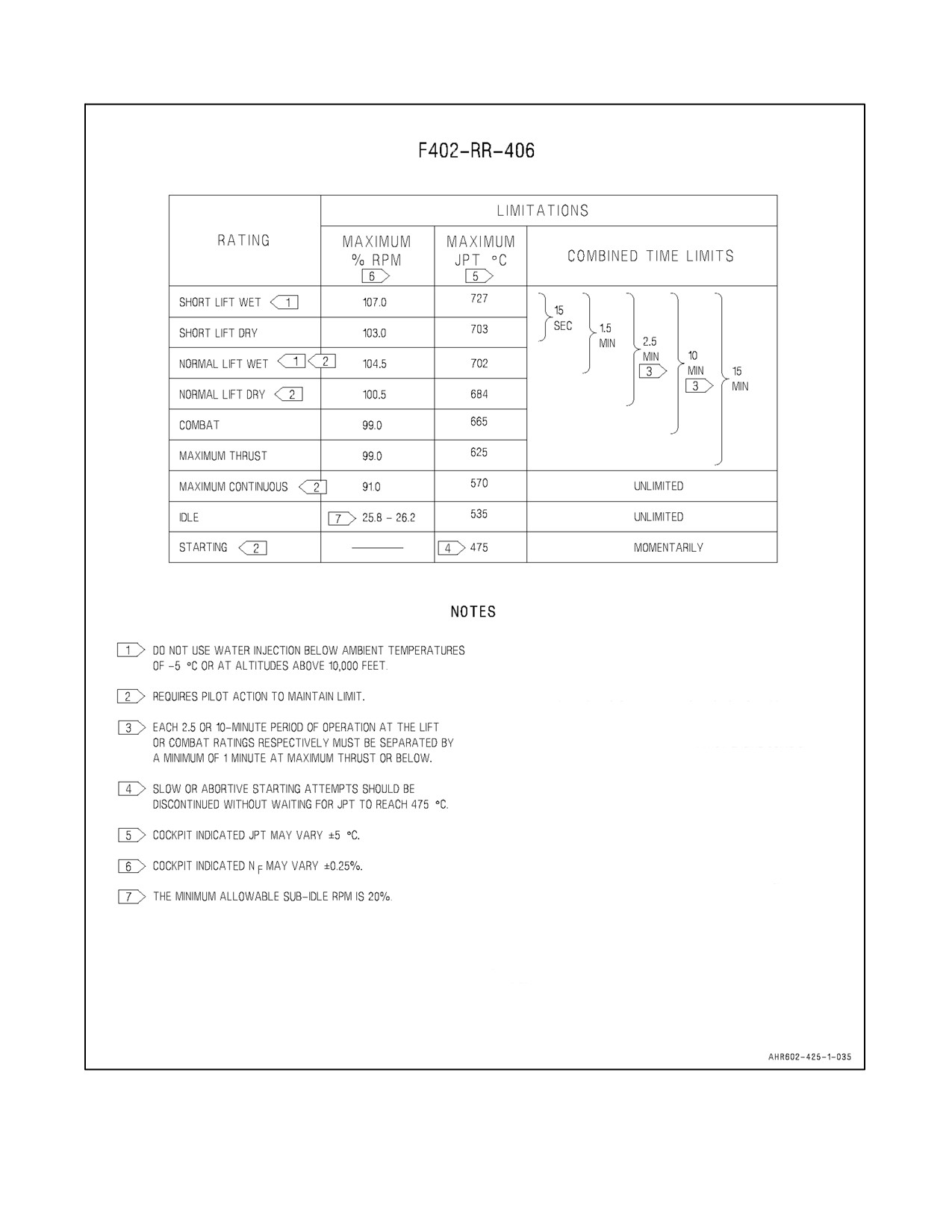
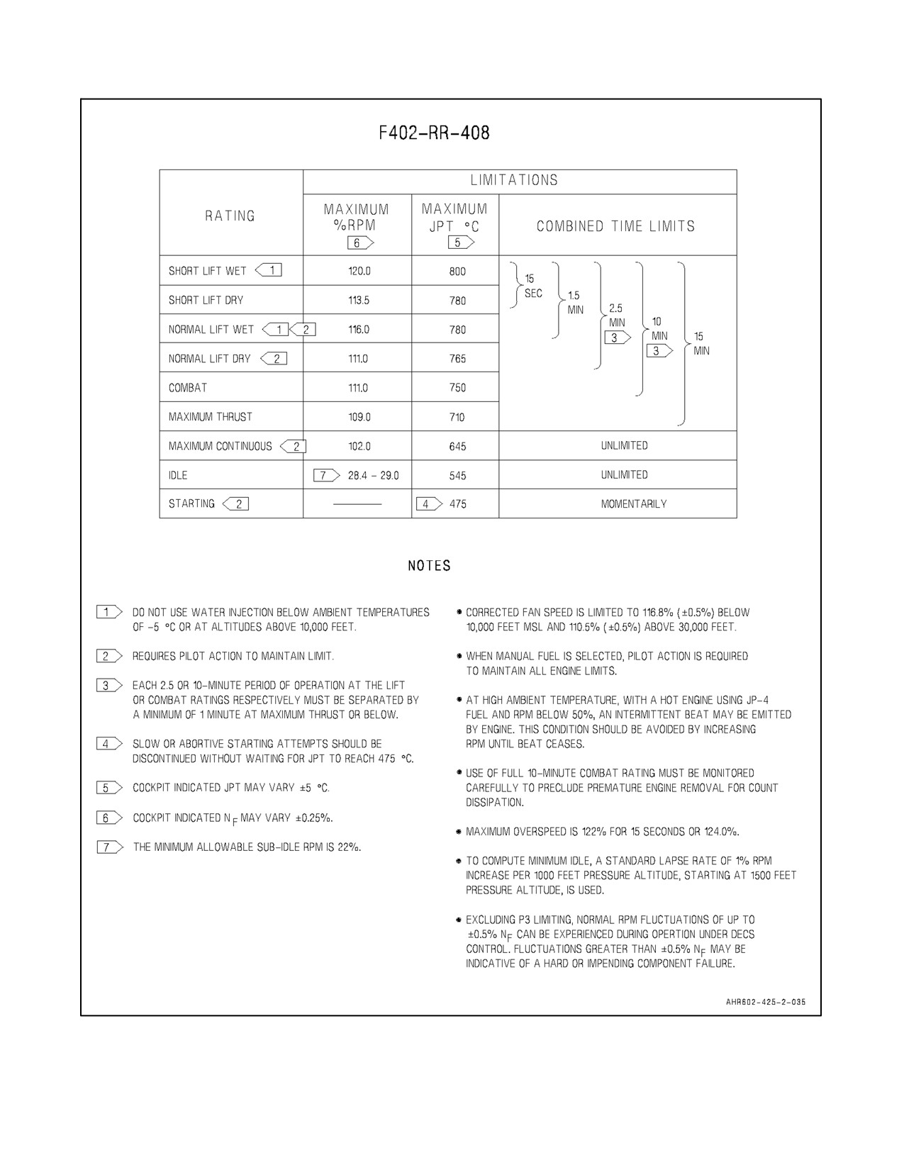
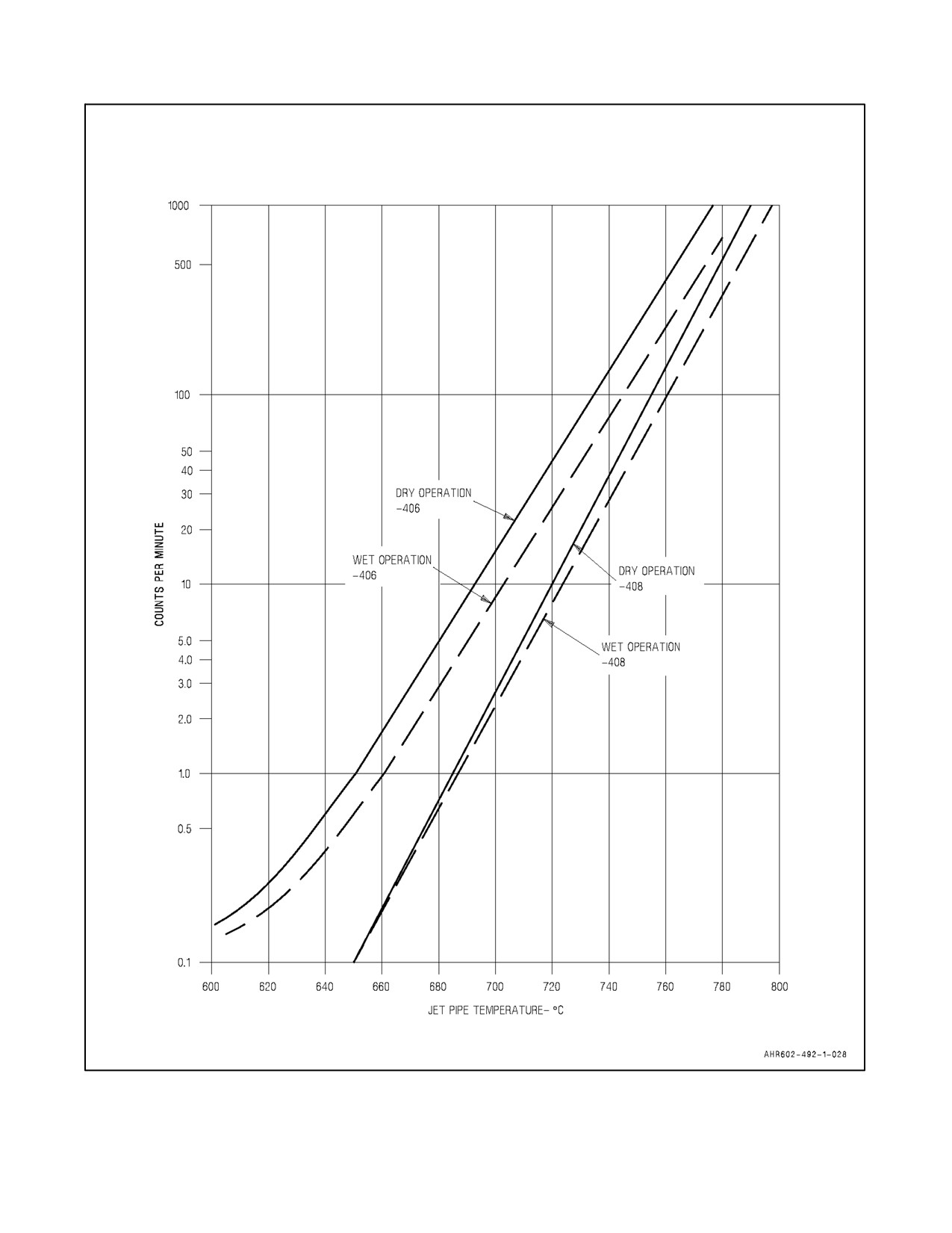
Refer to Figure 4-2 for engine operating limitations, and Figure 4-3 for engine life count rate versus JPT.
4.2.1 Fuel
The engine is cleared for use with the following fuel grades and their corresponding NATO code.
Primary Fuels are JP--5 (NATO F44), JP--8 (NATO F34), Jet A, Jet A--1.
Alternate Fuels are JP--4 (NATO F40), NATO F35, and Jet B.
CAUTION
Flight above 20,000 feet using JP--4, both boost pumps off, and fuel
proportioner off may result in engine flame out.
The+100fueladditiveandaerosol introducedPRIST (FSII)arenotallowed innaval aircraft.Premixed PRIST(FSII)
is allowable.
DECS will automatically compensate for the change in fuel specific gravity, and the aircraft is cleared for all normal
operations (Figure 4-1).
4.2.2 RPM Limits
The maximum indicated rpm for the F402--RR--406 engine is limited to 107.0 percent due to structural limits and
to 106.5 percent corrected rpm due to maximum flow limits.
The maximum indicated rpm for the F402--RR--408 engine is limited to 120.0 percent due to structural limits and
to 116.8 percent corrected rpm due to maximum flow limits.
RPM corrected to a standard day is referred to as corrected or non--dimensional rpm. The corrected rpm is
automatically limited by DECS.
4.2.3 Oil System
Engine turbine oil MIL--PRF--23699 (NATO Code 0--156) must be used. Maximum oil consumption is 3.75 pints
per hour. Flight in less than 1g conditions must not exceed 15 seconds continuous duration to avoid oil starvation
of the engine bearings.
4-1
ORIGINAL
A1-AV8BB--NFM--000
AV--8B FUEL REFERENCE CHART
US
COMMERCIAL
BRITISH
WT
NATO
US MILITARY
MIL
DESIGNATION
DESIGNATION
(LBS/
COMMENTS
CODE
SPECIFICATION
CODE
(SPECIFICATION)
(SPECIFICATION)
GAL)
PRIMARY
DEF STAN 91--86
JP--5
F--44
MIL--DTL--5624
NONE
6.8
1A, 2
FUELS
(AVCAT/FSII)
DEF STAN 91--87
JP--8
F--34
MIL--DTL--83133
NONE
6.7
1A, 2, 3
(AVTUR/FSII)
DEF STAN 91--88
JP--4
F--40
MIL--DTL--5624
NONE
6.5
1A, 2, 3, 4
(AVTAG/FSII)
RESTRICTED
JET A--1
DEF STAN 91--91
NONE
F--35
MIL--DTL--83133
6.7
1B, 3, 5, 6
FUELS
(ASTM D--1655)
(AVTUR)
JET A
NONE
NONE
NONE
NONE
6.7
1B, 3, 5, 6
(ASTM D--1655)
JET B
NONE
NONE
NONE
NONE
6.5
1B, 3, 4, 5, 6
(ASTM D--6615)
GOST 10227
NONE
NONE
NONE
NONE
6.7
1B, 3, 5, 6, 7
GRADE TS--1
EMERGENCY
JP--8
DEF STAN 91--87
F--37
MIL--DTL--83133
NONE
6.7
1C, 2, 8
FUELS
+100
(AVTUR/FSII + S--1749)
CAUTION
D
TO ENSURE THAT THEY CAN BE SAFELY HANGARED ABOARD SHIP,
AIRCRAFT SHOULD BE FUELED WITH JP--5 (F--44) PRIOR TO SEA BASING.
WHEN FUELING WITH JP--5 IS NOT POSSIBLE, AIRCRAFT SHALL NOT BE
HANGARED UNTIL THE FLASHPOINT OF THE FUEL IN THE AIRCRAFT FUEL
TANKS IS ABOVE 120 °F. NAVAIR 00--80T--109, SECTION 6.2.10 CONTAINS
THOSE PROCEDURES THAT MUST BE FOLLOWED WHEN HANGARING
AIRCRAFT CONTAINING FUEL OTHER THAN JP--5 (F--44).
D
SHIP’S FUEL PERSONNEL HAVE TEST EQUIPMENT FOR MEASURING
FUEL FLASHPOINT. FIGURE
4
OF MIL--HDBK--844A(AS)
(AIRCRAFT
REFUELING HANDBOOK FOR NAVY/MARINE CORPS AIRCRAFT) CAN BE
USED WITH THE MEASURED FLASHPOINT TO DETERMINE MORE
ACCURATELY THE PERCENTAGE OF JP--5 (F--44) REQUIRED TO RAISE
THE FLASHPOINT OF JP--8 (F--34) OR JET A--1 (F--35) ABOVE 120 °F.
D
OPERATION OF THE AV--8B AIRCRAFT IS RESTRICTED TO AMBIENT
TEMPERATURES ABOVE 0 °C (+32 °F) WHEN USING FUEL WHICH DOES
NOT CONTAIN FUEL SYSTEM ICING INHIBITOR (FSII). OPERATION BELOW
0 °C WITH FUEL THAT DOES NOT CONTAIN FSII MAY RESULT IN THE ICING
OF THE ENGINE FUEL FILTER AND LOSS OF FUEL FLOW TO THE ENGINE.
WHEN USING FUELS WHICH DO NOT CONTAIN FSII IT IS ESPECIALLY
IMPORTANT TO REMOVE WATER FROM THE AIRCRAFT’S LOW POINT
DRAINS TO MINIMIZE THE POSSIBILITY OF ICING AND MICROBIOLOGICAL
GROWTH.
D
PILOTS/AIRCREW SHALL ENSURE THAT AIRCRAFT MAINTENANCE
DEPARTMENTS ARE INFORMED WHEN AIRCRAFT ARE FUELED WITH THE
EMERGENCY FUEL JP--8+100 (F--37).
D
NAVAIR 00--80T--109 (AIRCRAFT REFUELING NATOPS MANUAL) CONTAINS
SPECIAL PROCEDURES THAT MUST BE FOLLOWED WHEN IT BECOMES
NECESSARY TO DEFUEL AIRCRAFT THAT HAVE BEEN FUELED WITH THE
EMERGENCY FUEL JP--8+100 (F--37). SINCE THERE IS NO VIABLE FIELD
TEST THAT CAN DETECT THE PRESENCE OF JP--8+100
(F--37),
PILOTS/AIRCREW AND AIRCRAFT MAINTENANCE PERSONNEL SHALL
ENSURE THAT FUELS PERSONNEL ARE INFORMED OF AIRCRAFT THAT
HAVE BEEN FUELED WITH THE EMERGENCY FUEL JP--8+100 (F--37).
Figure 4-1. AV--8B Fuel Reference Chart (Sheet 1 of 2)
ORIGINAL
4-2

A1-AV8BB--NFM--000
COMMENTS
1.
FUEL DEFINITIONS:
a. PRIMARY FUEL -- A FUEL THAT THE AIRCRAFT IS AUTHORIZED TO USE FOR CONTINUOUS UNRESTRICTED
OPERATIONS.
b. RESTRICTED FUEL -- A FUEL WHICH IMPOSES OPERATIONAL RESTRICTIONS ON THE AIRCRAFT. THESE FUELS MAY
BE USED ONLY IF NO PRIMARY MILITARY OR COMMERCIAL FUELS ARE AVAILABLE.
c. EMERGENCY FUEL -- A FUEL WHICH MAY BE USED FOR A MINIMUM TIME WHEN A PRIMARY OR RESTRICTED FUEL
IS NOT AVAILABLE AND AN URGENT NEED EXISTS (SUCH AS HURRICANE EVACUATION OR URGENT MILITARY
NECESSITY). PILOT APPROVAL SHALL BE OBTAINED BEFORE SERVICING AND THE AIRCRAFT SHALL BE
CONSPICUOUSLY PLACARDED WITH THE EMERGENCY FUEL GRADE WHEN SERVICED.
2.
ALL US MILITARY AND NATO FUELS, EXCEPT F--35, CONTAIN AN ADDITIVE PACKAGE WHICH INCLUDES FUEL SYSTEM
ICING INHIBITOR (FSII).
3.
JP--4, JP--8, TS--1, JP--8+100 AND ALL COMMERCIAL JET FUELS SHALL NOT BE DEFUELED INTO SHIPBOARD JP--5 FUEL
STORAGE TANKS BECAUSE THE FLASH POINT OF THESE FUELS IS LESS THAN 140 °F.
4.
JP--4 (F--40) HAS BEEN REPLACED BY JP--8 (F--34) IN US AND NATO SERVICE. JP--4 (F--40) AND JET B ARE NO LONGER
WIDELY AVAILABLE WORLDWIDE BUT MAY STILL BE ENCOUNTERED IN SOME AREAS.
5.
COMMERCIAL FUELS ARE AVAILABLE BOTH WITH AND WITHOUT FSII. SEE THE CAUTION ABOVE WHEN OPERATING THE
AV--8B AIRCRAFT ON FUELS THAT DO NOT CONTAIN FSII.
6.
PRIST. A COMMERCIAL FSII ADDITIVE, PRIST, MAY BE USED WITH COMMERCIAL JET FUEL (JET A/JET A--1/JET B). PRIST
IS EQUIVALENT TO THE MILITARY FSII ADDITIVE. IT IS AVAILABLE IN TWO FORMS: (1) AEROSOL CANS WHICH ARE
DISCHARGED INTO THE FUEL AS IT IS PUMPED INTO THE AIRCRAFT AND (2) PRE--MIXED INTO THE FUEL. WHEN PRIST
IS PREMIXED WITH THE FUEL IT PROVIDES ANTI--ICING PROTECTION EQUIVALENT TO THAT PROVIDED BY MILITARY JET
FUEL AND IS AUTHORIZED FOR USE. PRIST IN AEROSOL CANS IS NOT AUTHORIZED FOR USE SINCE IT DOES NOT MIX
WELL WITH FUEL, HAS A TENDENCY TO SETTLE TO THE BOTTOM OF FUEL TANKS, AND MAY DAMAGE FUEL SYSTEM
SEALS AND FUEL TANK MATERIALS.
7.
TS--1 IS A COMMERCIAL AVIATION KEROSENE MADE TO THE RUSSIAN FUEL SPECIFICATION GOST 10227. IT IS VERY
SIMILAR TO ASTM JET A--1 WITH THE EXCEPTION THAT THE FLASH POINT IS APPROXIMATELY 20 °C LOWER THAN JET
A--1. THIS FUEL IS COMMONLY AVAILABLE IN RUSSIA, PARTS OF CENTRAL EUROPE, THE CENTRAL ASIAN REPUBLICS
AND AFGHANISTAN.
CAUTION
TS--1 CONTAINING THE RUSSIAN FSII ADDITIVE IS NOT AUTHORIZED FOR USE. ITS IMPACT ON
NAVY AND MARINE CORPS AIRCRAFT HAS NOT BEEN DETERMINED.
8.
JP--8+100 (F--37) CONTAINS A THERMAL STABILITY ADDITIVE THAT AFFECTS THE ABILITY OF THE COALESCING
FILTER--SEPARATORS AND CENTRIFUGAL PURIFIERS (FILTRATION EQUIPMENT USED IN SHORE STATION AND
SHIPBOARD FUEL STORAGE/HANDLING SYSTEMS) TO REMOVE FREE WATER AND FINE PARTICULATE MATTER FROM
FUEL. NAVAIR 00--80T--109 (AIRCRAFT REFUELING NATOPS MANUAL) CONTAINS ADDITIONAL INFORMATION ON
JP--8+100 (F--37). NO USN/USMC AIRCRAFT ENGINES REQUIRE THE USE OF JP--8+100 (F--37). USN/USMC AIRCRAFT ARE
NOT AUTHORIZED TO USE JP--8+100 (F--37) EXCEPT IN EMERGENCY SITUATIONS.
FOR ADDITIONAL INFORMATION ON AVIATION FUELS, CONSULT THE FOLLOWING:
1. NAVAIR 00--80T--109, AIRCRAFT REFUELING NATOPS MANUAL.
2. MIL--HDBK--844A (AS), REFUELING HANDBOOK FOR NAVY/MARINE CORPS AIRCRAFT.
Figure 4-1. AV--8B Fuel Reference Chart (Sheet 2)
4-3
ORIGINAL
A1-AV8BB--NFM--000
D CORRECTED FAN SPEED IS LIMITED TO 106.5% (±0.5%) BELOW
10,000 FEET MSL AND 102.5% (±0.5) ABOVE 30,000 FEET.
D WHEN MANUAL FUEL IS SELECTED, PILOT ACTION IS REQUIRED TO
MAINTAIN ALL ENGINE LIMITS. MAXIMUM THROTTLE POSITION IN MFS WILL
PROVIDE APPROXIMATELY 111.0% CORRECTED FAN SPEED VERSUS THE
116.8% CORRECTED FAN SPEED LIMITATION PROVIDED UNDER DECS
CONTROL. ACTUAL MECHANICAL SPEED AND THRUST ACHIEVED IN MFS
WILL VARY WITH AMBIENT CONDITIONS. ANTICIPATE MAXIMUM
ACHIEVABLE MFS PERFORMANCE EQUAL TO OR SLIGHTLY LESS THAN
SHORT LIFT DRY PERFORMANCE UNDER DECS CONTROL WHEN
OPERATING NEAR SEA LEVEL STATIC CONDITIONS.
D AT HIGH AMBIENT TEMPERATURE, WITH A HOT ENGINE USING JP--4 FUEL
AND RPM BELOW 50%, AN INTERMITTENT BEAT MAY BE EMITTED BY
ENGINE. THIS CONDITION SHOULD BE AVOIDED BY INCREASING RPM
UNTIL BEAT CEASES.
D USE OF FULL 10--MINUTE COMBAT RATING MUST BE MONITORED
CAREFULLY TO PRECLUDE PREMATURE ENGINE REMOVAL FOR COUNT
DISSIPATION.
D MAXIMUM OVERSPEED IS 109% FOR 15 SECONDS OR 110%.
D TO COMPUTE MINIMUM IDLE, A STANDARD LAPSE RATE OF 1% RPM
INCREASE PER 1,000 FEET PRESSURE ALTITUDE, STARTING AT 1,500 FEET
PRESSURE ALTITUDE, IS USED.
D EXCLUDING P3 LIMITING, NORMAL RPM FLUCTUATIONS OF UP TO ±0.5 NF
CAN BE EXPERIENCED DURING OPERATION UNDER DECS CONTROL.
FLUCTUATIONS GREATER THAN ±0.5% NF MAY BE INDICATIVE OF A HARD
OR IMPENDING COMPONENT FAILURE.
Figure 4-2.
Engine Operating Limitations (Sheet 1 of 2)
ORIGINAL
4-4
A1-AV8BB--NFM--000
Figure 4-2. Engine Operating Limitations (Sheet 2)
4-5
ORIGINAL
A1-AV8BB--NFM--000
Figure 4-3. Engine Life Count Rates Versus JPT
ORIGINAL
4-6
A1-AV8BB--NFM--000
4.2.4 Engine Starting Limitations
A starting attempt should be abandoned immediately if:
1. RPM stagnates below idle rpm.
2. JPT reaches 475 °C. If JPT rises rapidly between 350 °C and 400 °C, throttle OFF before 475 °C.
3. Light up has not occurred within 10 seconds of selecting idle.
4. Engine should not be started with flaps greater than 25°.
Do not select idle after start on a hot engine until JPT is below 150 °C.
Note
Engine start should not be attempted if OAT is less than --35 °C or greater
than 52 °C.
If the engine fails to light, a fuel drainage period of 1 minute must be allowed before a further starting attempt is made.
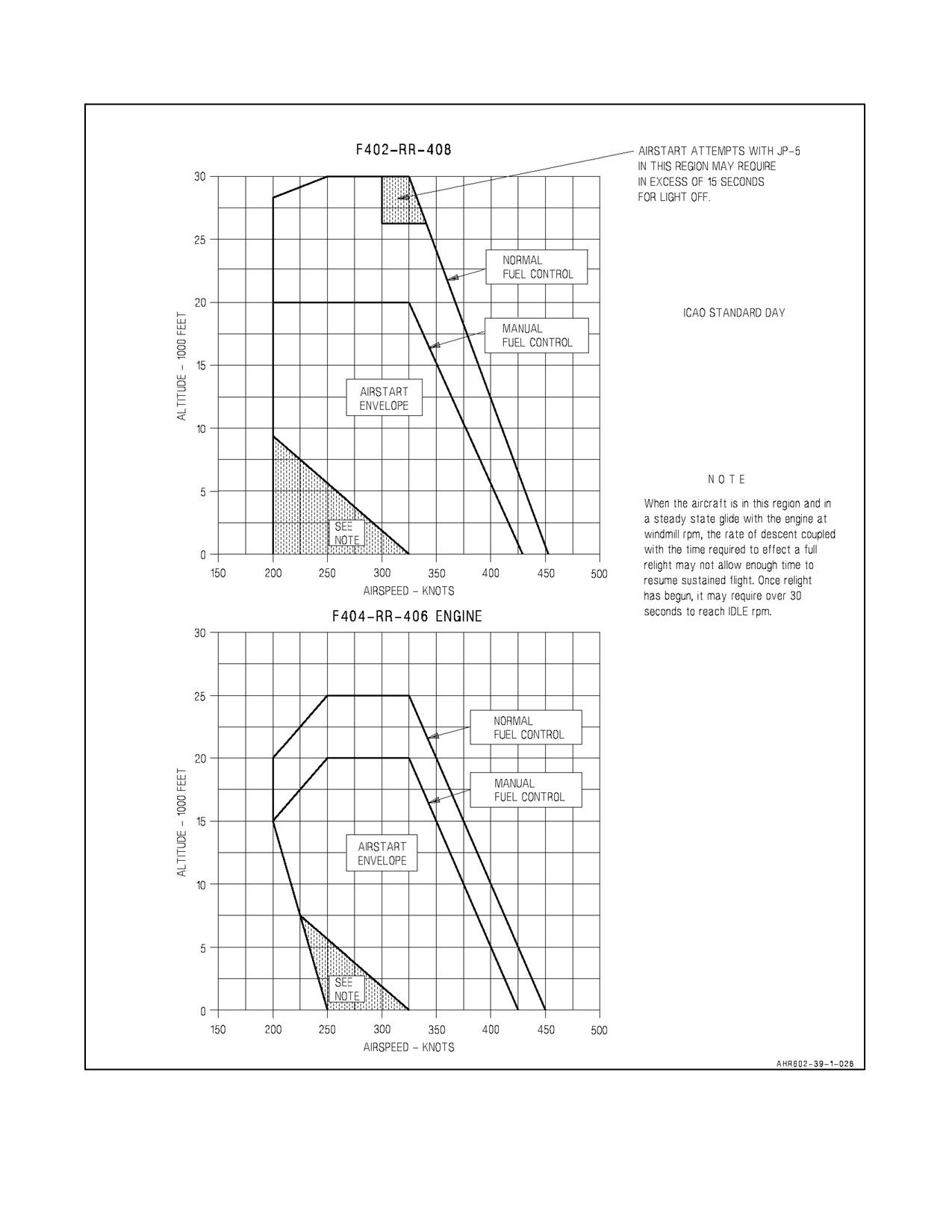
4.2.5 Engine Airstart Envelope
See Figure 4-4.
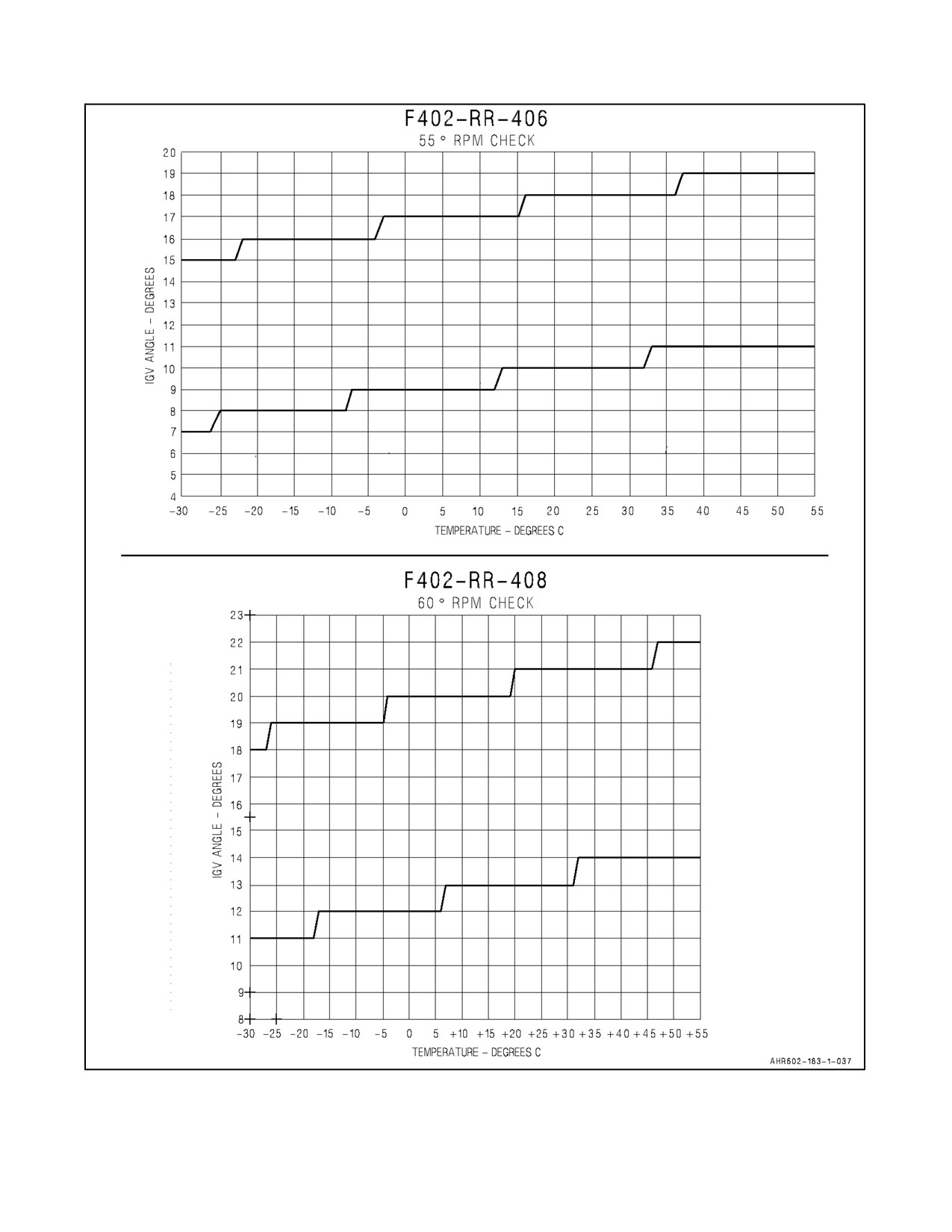
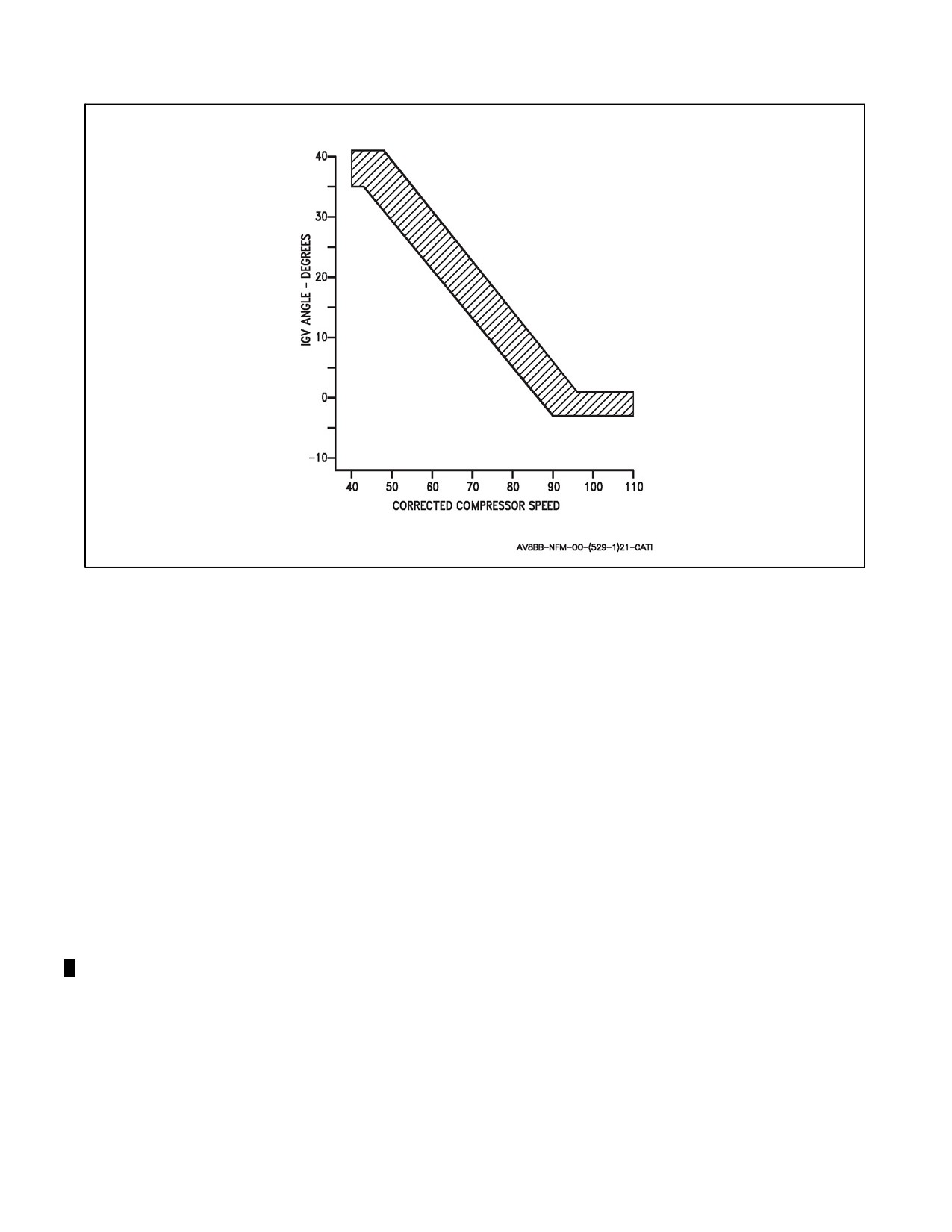
4.2.6 Inlet Guide Vane Angles
For the F402--RR--406 engine the IGV setting band at 55 percent rpm is presented in Figure 4-5.
For the F402--RR--408 engine the IGV setting band at 60 percent rpm is presented in Figure 4-5.
The IGV schedule presented in Figure 4-6 is applicable to both --406 and --408 engines.
4.2.7 Water Injection Limitations
Distilled or demineralized water (per NAVAIR Instruction 13780.1) must be used whenever possible. Repeated use
of other than distilled or demineralized water results in deterioration of engine performance. Water injection is not
to be used if OAT is below --5 °C.
4.2.8 Engine Bleed Limitations
More than 5 minutes of continuous engine bleed in hover flight is prohibited. Continuous hover flight must be
followed by a cooling period (forward flight or ground operations) of the same duration.
4.3
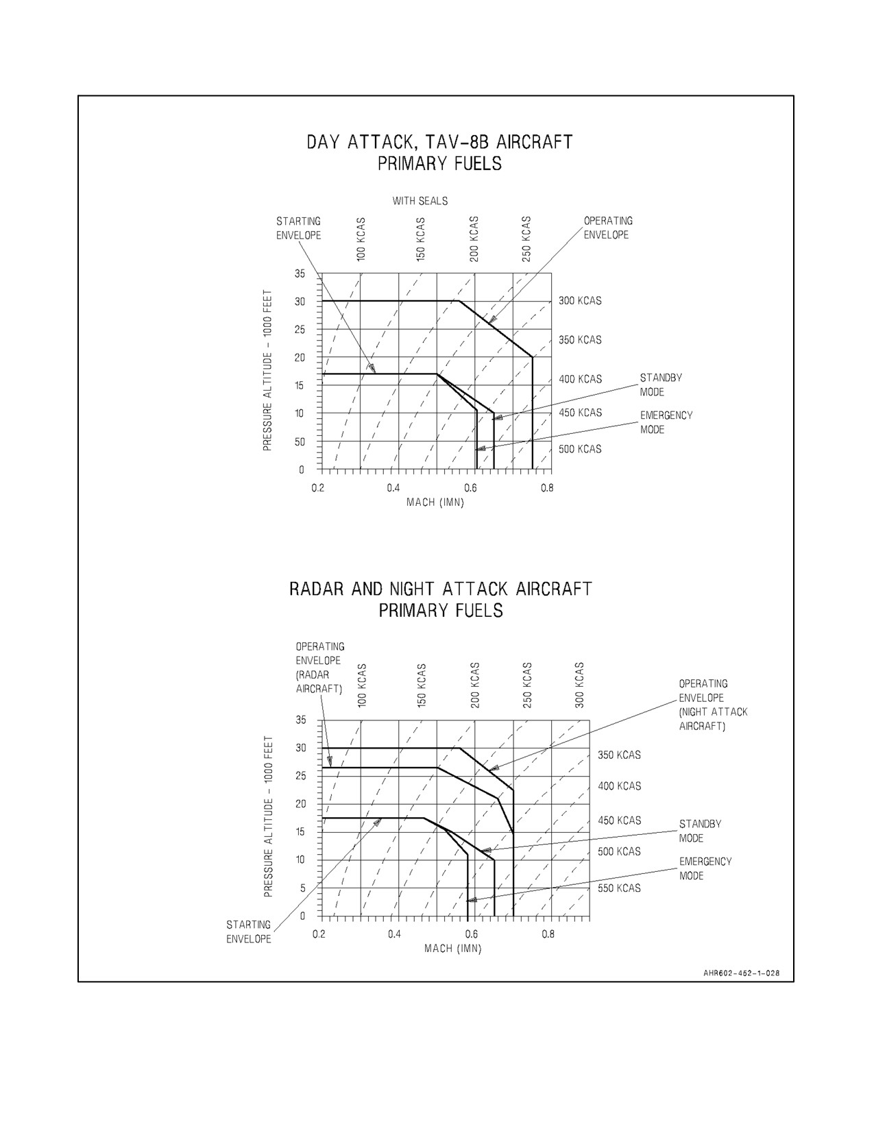
APU STARTING AND OPERATING ENVELOPE
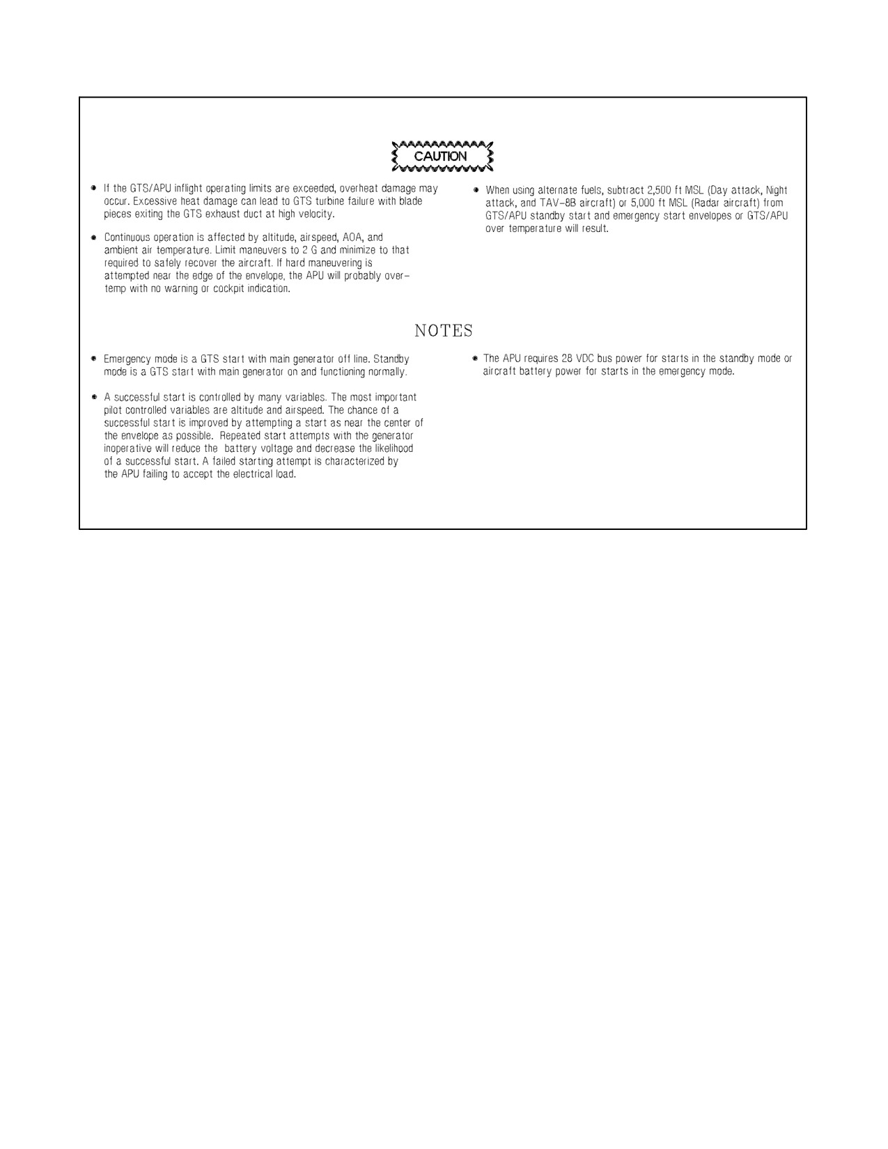
Unless an external air supply is used to cool the electric starter motor, no more than three GTS/APU start cycles
(within a 20 minute period) may be made, with at least 1 minute between attempts. To prevent damage/failure to the
GTS main gearbox, engine start cycle may not be repeated following a failed or aborted engine start attempt until
engine HP compressor rotation completely stops and the minimum 1 minute interval between start attempts is met.
Refer to Figure 4-7 for inflight APU starting and operating envelope.
4.4
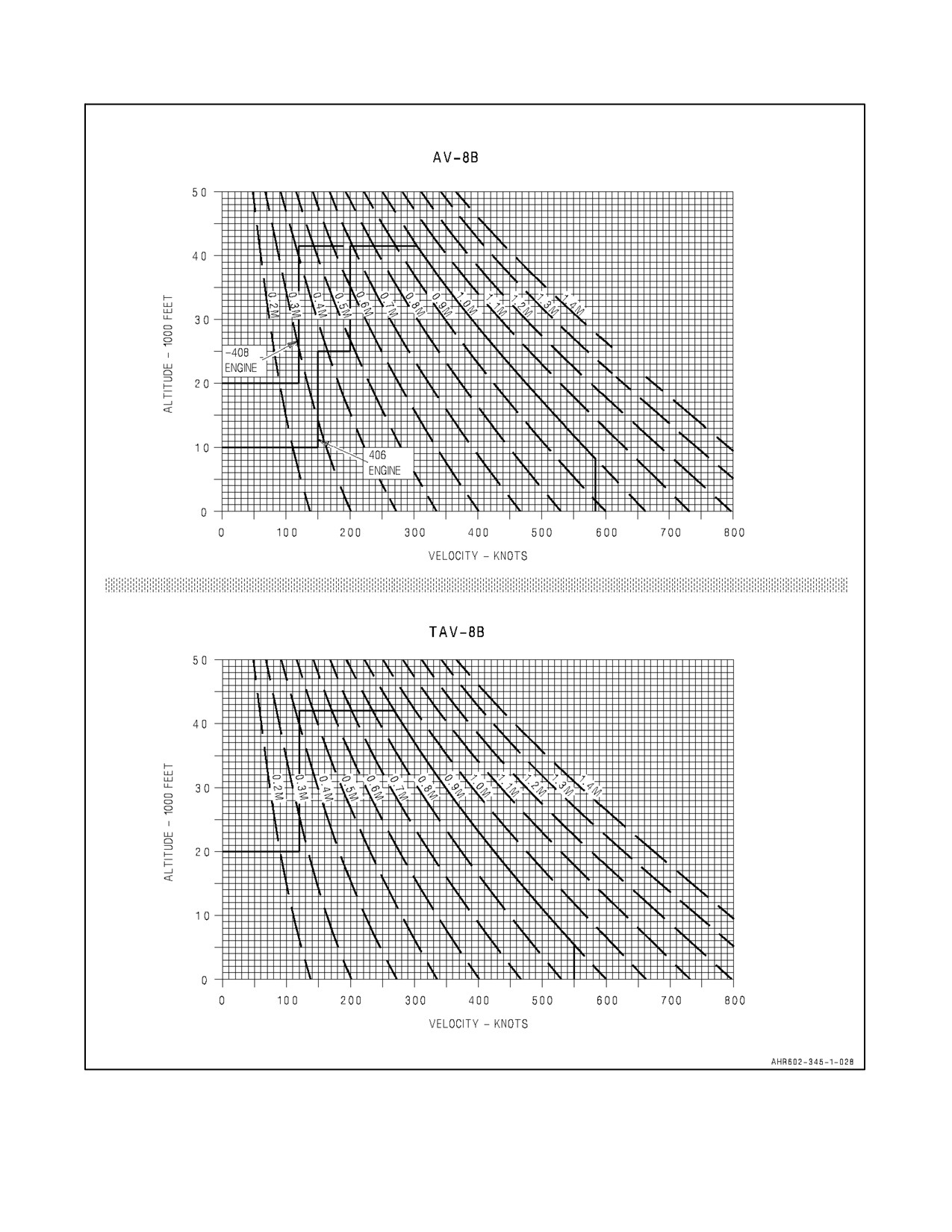
AIRSPEED LIMITATIONS
The maximum permissible airspeeds for flight in smooth or moderately turbulent air with landing gear and flaps
retracted, the speed brake retracted, and Q--feel engaged is shown in Figure 4-8. The maximum permissible
airspeed/Mach number, whichever is less:
AV--8B - 585 KCAS/1.0 indicated mach number (IMN).
TAV--8B - 550 KCAS/0.9 IMN.
4-7
ORIGINAL
A1-AV8BB--NFM--000
Figure 4-4. Engine Airstart Envelope
ORIGINAL
4-8
A1-AV8BB--NFM--000
Figure 4-5. Effect of OAT on Variable Inlet Guide Vanes Engine
4-9
ORIGINAL
A1-AV8BB--NFM--000
Figure 4-6. IGV Schedule
Airspeed limitations for various systems are as follows:
1.
Flaps: STOL — 300 knots CRUISE — 0.87 Mach.
2.
Landing gear operation — 250 knots.
3.
Landing gear locked down — 250 knots.
4.
Landing gear emergency extension — 210 knots.
5.
Q--feel disengaged — 500 knots.
6.
One hydraulic system inoperative — 500 knots.
7.
Canopy open — 40 knots.
8.
Wheels in contact with ground — 180 knots ground speed.
9.
LIDS fence extended — 200 knots.
10.
Air refueling probe extended — 300 knots.
11.
Max airspeed for STOL flap landings — 130 knots.
12.
With F402--RR--406 engine before PPC 170 and sea level ambient temperature below --1 °F and pressure
altitude below 2,500 feet — 510 KCAS. With F402--RR--406 engine after PPC--170 — Normal limits.
4.5
PROHIBITED MANEUVERS (ALL AIRCRAFT)
1.
Vertical takeoff with asymmetric load/stores greater than 45,000 inch--pounds.
2.
STO with asymmetric load/stores greater than 85,000 inch--pounds or conventional takeoff (CTO) with
asymmetric load/stores greater than 100,000 inch--pounds.
ORIGINAL
4-10
A1-AV8BB--NFM--000
Figure 4-7. APU Starting and Operating Envelope (Sheet 1 of 2)
4-11
ORIGINAL
A1-AV8BB--NFM--000
Figure 4-7. APU Starting and Operating Envelope (Sheet 2)
3.
Shipboard STO with asymmetric load/stores greater than 57,270 inch--pounds.
4.
AUTO flaps — Slow landing (SL) with more than 148,000 inch--pounds asymmetry, or STOL flaps — SL
with more than 85,000 inch--pounds asymmetry.
5.
Vertical landing (VL) with more than 80,000 inch--pounds asymmetry.
6.
Takeoff with less than 10° nozzles until wingborne.
7.
Spin.
8.
Under 1 g for more than 15 seconds.
9.
Overriding aileron high speed stop.
10.
Roll over 360°.
11.
In accelerating or decelerating transition:
a. Over 15° AOA above 50 knots with landing gear down.
b. Between 30 to 100 knots, sideslip requiring more than 1/2 lateral stick or with RPS on.
12.
Rearward or sideward translation above 30 knots.
13.
TVC above 20,000 feet Mean Sea Level (MSL) with the --406 engine or 30,000 feet MSL with the --408 engine
at AOA above onset of stall warning/maneuvering tone or at less than 0 g.
14.
Over 80 percent rpm above 25,000 feet MSL at less than 0 g (--406 engine only).
15.
Flight above onset of stall warning/maneuvering tone with more than 60,000 inch--pounds asymmetry.
16.
Abrupt simultaneous stabilator, rudder, or aileron inputs with more than 90,000 inch--pounds asymmetry.
17.
Wingborne flight at any speed with more than 148,000 inch--pounds asymmetry, or flight above 0.88 Mach
with more than 90,000 inch--pounds asymmetry. For asymmetries above 90,000 inch--pounds, maneuvering
limit is 5 g, 10° AOA or stall warning, whichever occurs first.
ORIGINAL
4-12
A1-AV8BB--NFM--000
Figure 4-8. Airspeed Limitations
4-13
ORIGINAL
A1-AV8BB--NFM--000
18. Departure above 250 knots.
19. Rudder deflection above 0.80 Mach.
4.5.1 Prohibited Maneuvers (SAAHS OFF)
1. Departure or stall.
2. Roll over 180° above 8° AOA.
3. Abrupt input of more than 1/2 rudder.
4. More than 1/2 lateral stick beyond onset of stall warning or with flap switch in CRUISE.
4.5.2 Prohibited Maneuvers (TAV--8B)
All those for the AV--8B as presented in this manual including:
1. Intentional stalls, tail slides, departures, spins, or flops.
2. Airspeed less than 120 KCAS in nose high conditions.
3. Rolling maneuvers in excess of 180° at more than 1 g.
4. Wingborne or TVC maneuvering flight above maneuvering tone.
4.5.3 Prohibited Maneuvers (Radar Aircraft)
All those for the AV--8B as presented in this manual including:
1. Abrupt (less than 1/2 second) lateral stick inputs to high speed stops with SAAHS — ON, above 3 g for speeds
greater than 475 KCAS at altitudes less than 10,000 feet MSL.
2. Abrupt (less than 1/2 second) lateral stick inputs to high speed stops with SAAHS — OFF.
4.6
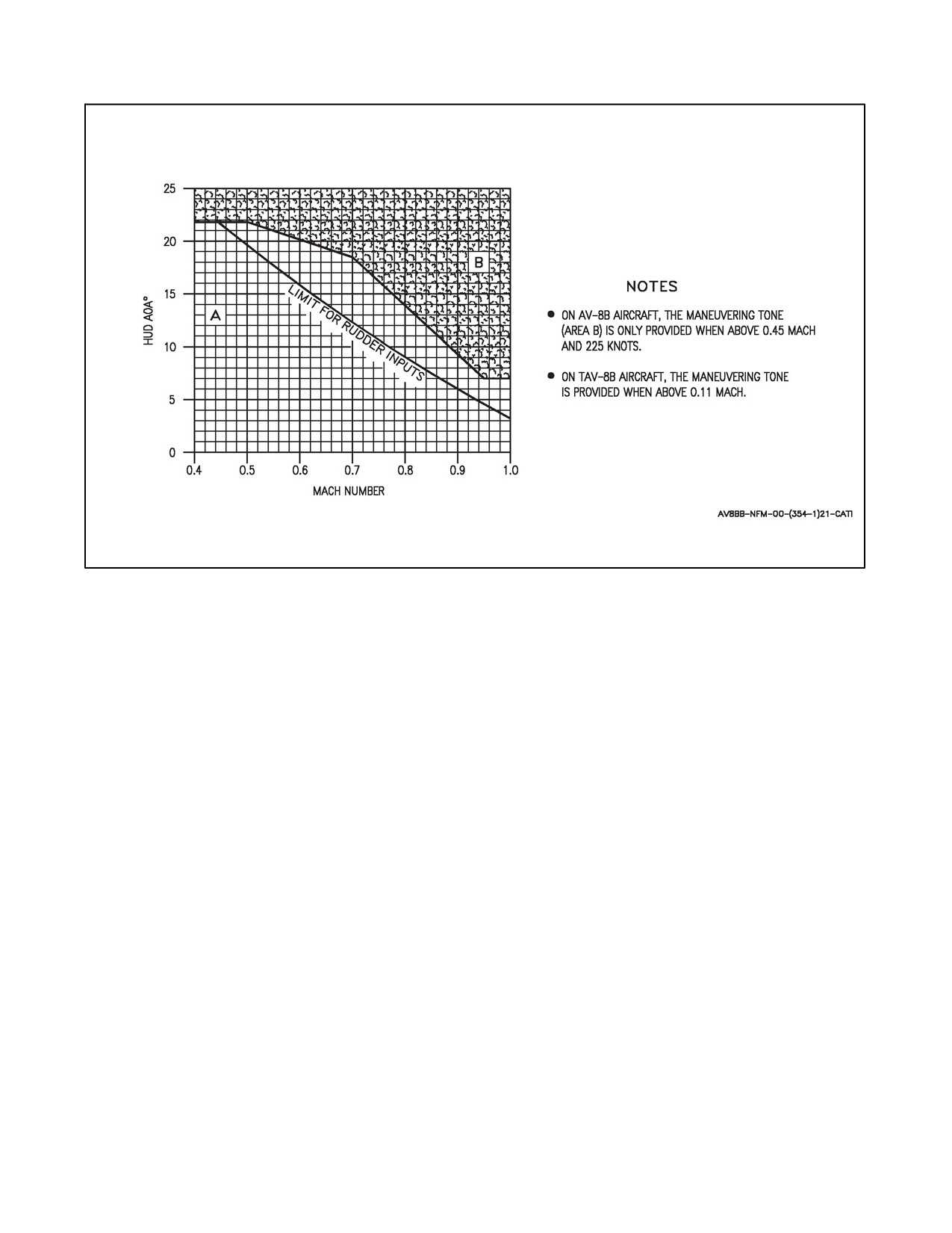
AOA LIMITATIONS (SAAHS OFF)
AOA limit versus Mach number with flaps AUTO, SAS OFF and nozzles 0° is shown in Figure 4-9. The limits are
coincident with the maneuvering tone. AOA is also limited to that where onset of buffet, wing rock or sideslip buildup
occurs. During abrupt maneuvers, HUD AOA lags the actual AOA.
4.7
CG LIMITATIONS
Refer to the Weight and Balance Data handbook, NAVAIR 01--1B--40.
4.8
WEIGHT LIMITATIONS
Maximum gross weight for taxi and takeoff is 32,000 pounds. Avoid abrupt maneuvering and hard braking at taxi
gross weights above 29,750 pounds. Maximum gross weight for landing is 26,000 pounds.
4.9
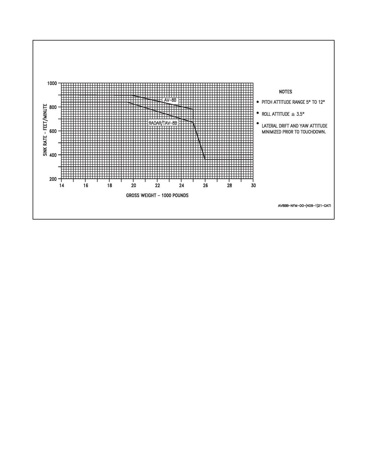
SINK RATE LIMITATIONS
See Figure 4-10. For sink rate limitations at gross weights above 25,000 pounds, use RADAR/TAV--8B limits.
4.10
ACCELERATION LIMITATIONS
1. The maximum permissible acceleration in the takeoff and landing configuration is 0.0 g to +2.0 g’s.
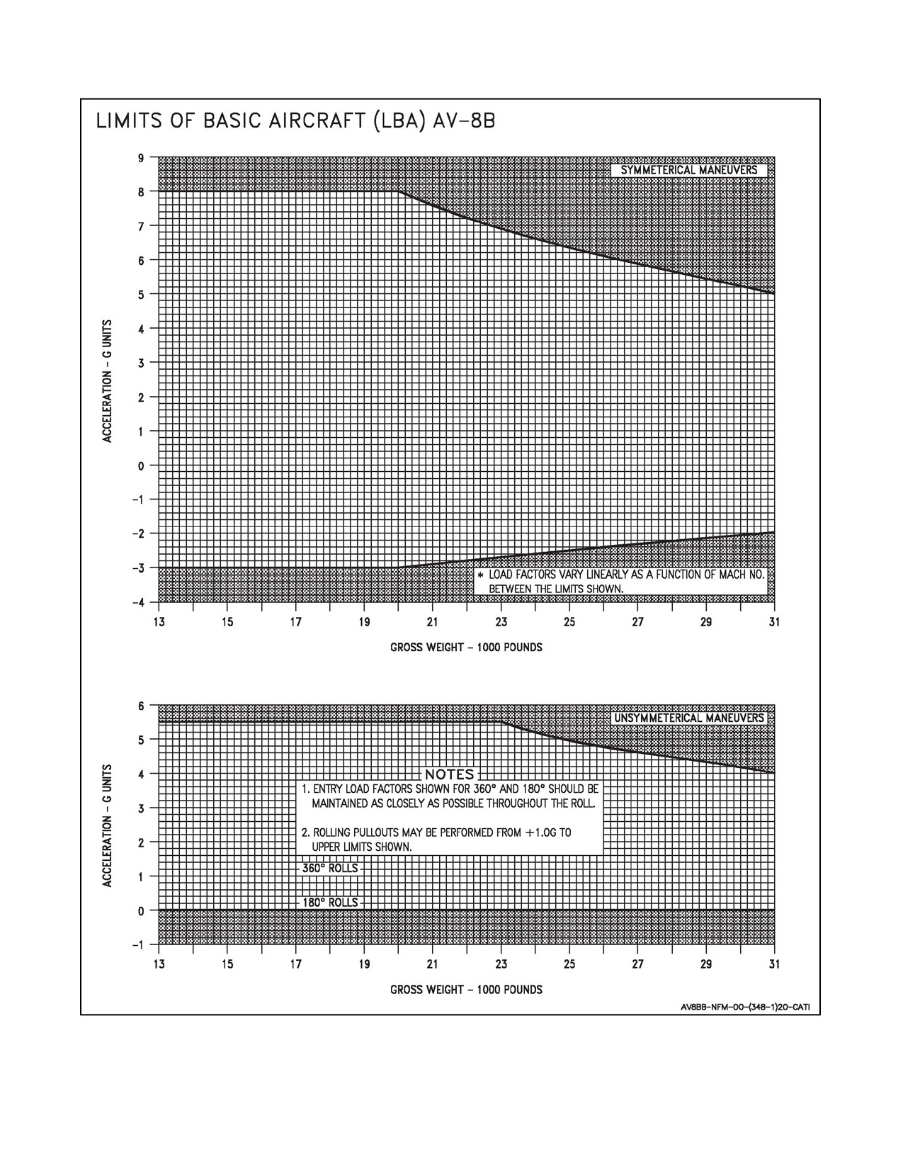
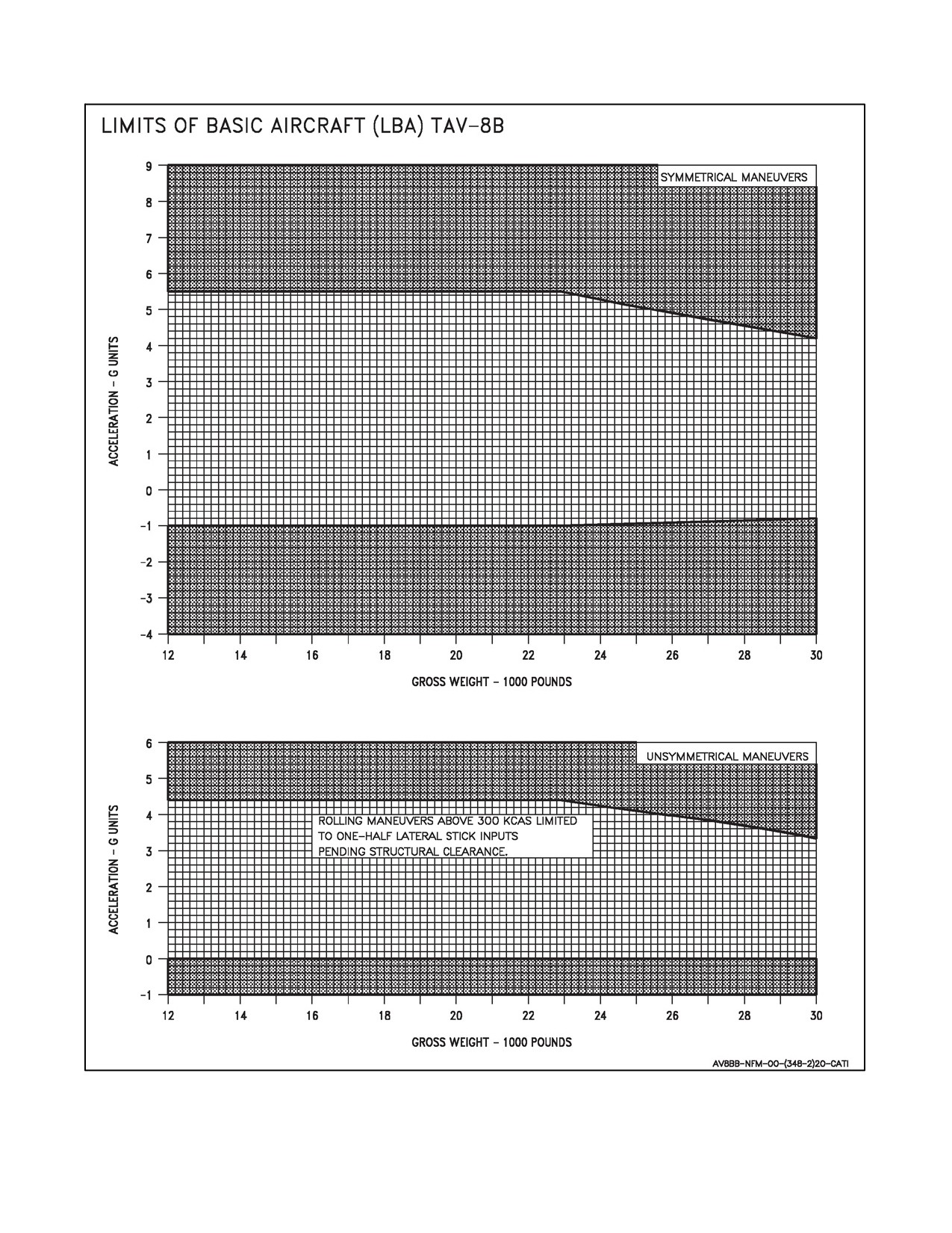
2. The maximum permissible acceleration in smooth air with flaps AUTO or CRUISE for aircraft with empty
pylons or air--to--air loads is shown in Figure 4-11. An air--to--air load is two AIM--9 on outboard pylons and
a gun.
3. For any other configuration, refer to Tactical Manual, A1--AV8BB--TAC--050, for external stores limitations.
ORIGINAL
4-14
A1-AV8BB--NFM--000
Figure 4-9. AOA Limits -- Flaps -- AUTO -- SAS OFF -- Nozzles 0°
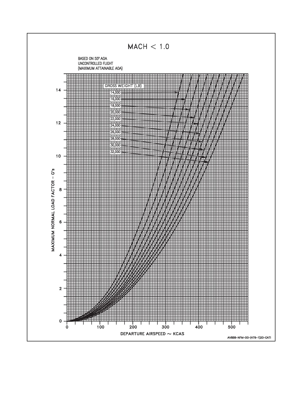
4. Following a departure, the pilot should use the Maximum Possible Normal Load Factor chart (Figure 4-12)
to estimate the maximum load factor (NZ) attained by the aircraft. An over--g inspection of the aircraft per the
A1--AV8BB--GAI--400 maintenance manual is required if the estimated NZ exceeds the allowable structural
load factor limit.
5. On TAV--8B, refer to Figure 4-11 for acceleration limitations.
4.11
CROSSWIND LIMITATIONS
Paved runway (minimum width 100 feet).
For wet runway operation, reduce crosswind limits by 5 knots.
4.11.1 Takeoffs
1. CTO (day or night) — 20 knots.
2. STO > 120 knots (day or night) — 15 knots.
3. STO ≦ 120 knots (day or night) — 10 knots.
4. RVTO Day — 10 knots, Night — 5 knots.
5. VTO (day or night) — 10 knots.
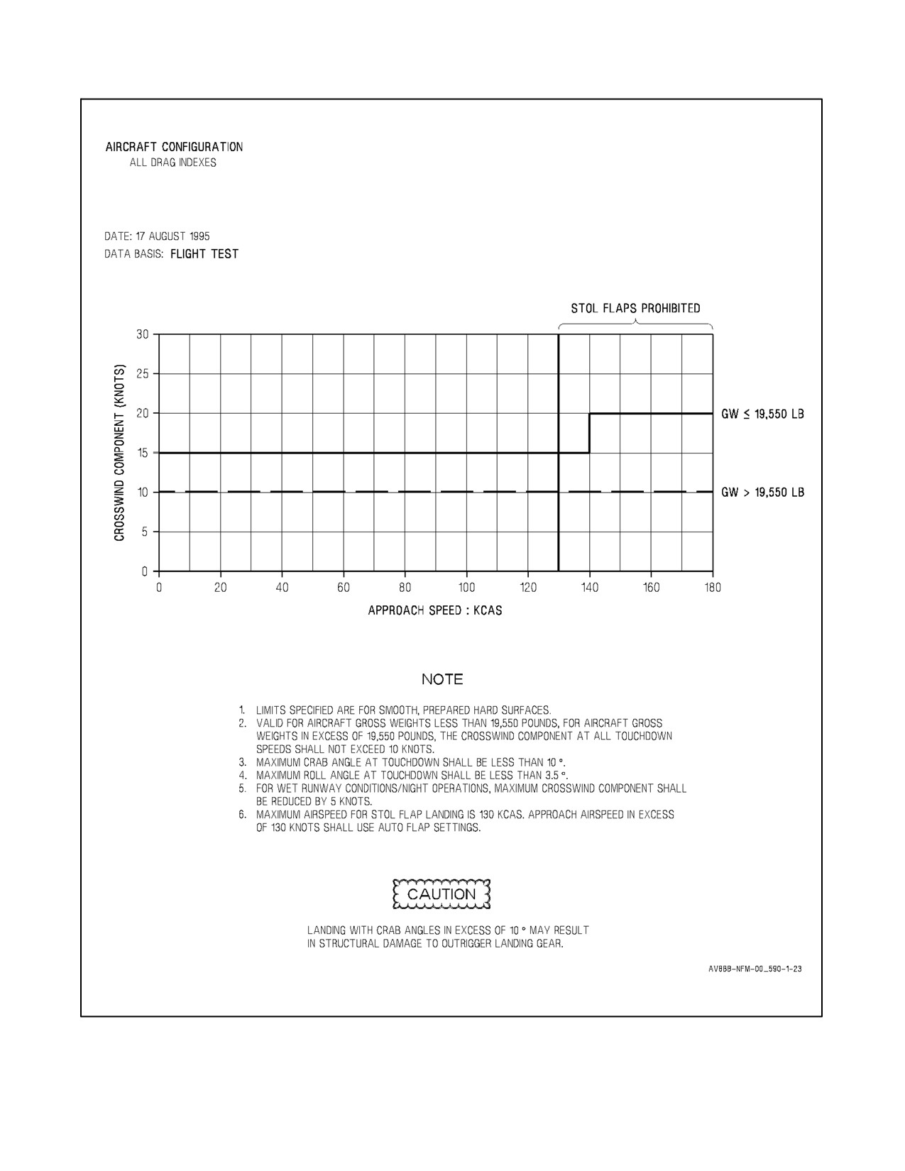
4.11.2 Landings
1. Approach speeds ≧ 140 knots Day — 20 knots, Night — 15 knots.
2. Approach speeds < 140 knots Day — 15 knots, Night — 10 knots.
3. Gross weights > 19,550 pounds, all approach speeds (day or night) — 10 knots.
(Due to outrigger stress limitations.)
4. Refer to Figure 4-13 for crosswind landing capability.
4-15
ORIGINAL
A1-AV8BB--NFM--000
4.12
ARRESTING GEAR LIMITATIONS
Theaircraftisclearedtotaxioverasupportedarrestinggearwireuptoamaximumspeedof5knots.Stopimmediately
if wing gear is trapped by the wire. The aircraft may cross an unsupported tensioned arresting gear wireat any speed,
engine rpm or nozzle angle if the wire lies flat on the runway or deck.
4.13
SYSTEMS LIMITATIONS
4.13.1 Global Positioning System
GPS is for tactical use only and does not meet Federal Aviation Administration (FAA) standards for en route or termi-
nal phase of flight.
4.13.2 All Weather Landing System
Use of AWLS is limited to weather minimum of 400--foot ceiling and 1 nm visibility.
4.13.3 Automatic Flight Controls
1. Use of basic attitude hold mode above 0.85 Mach is prohibited.
2. Use of altitude hold (ALT) below 500 feet AGL is prohibited.
3. Use of control stick steering in pitch with ALT engaged is prohibited.
4.13.4 Canopy (AV--8B)
1. Canopy open with wind over 40 knots is prohibited.
2. Canopy open with rpm over 70 percent is prohibited.
4.13.5 Canopy (TAV--8B)
1. Both canopies shall remain closed and locked during taxi. This restriction does not apply if the vent strap is
used to hold the canopy open.
4.13.6 Nozzle/Flap Limitations
1. During normal in--flight operations, with the exception of air refueling, use of STOL flaps is limited to nozzle
positions greater than 25°.
4.13.7 APG--65 Operations (Radar Aircraft)
1. Use of terrain avoidance mode of radar in instrument meteorology conditions is prohibited.
4.13.8 Software (H4.0 only)
1. Flight with a software configuration fault is prohibited.
4.14
EXTERNAL STORES LIMITATIONS
Refer to NATIP, NTRP 3--22.4--AV8B.
ORIGINAL
4-16
A1-AV8BB--NFM--000
Figure 4-10. Sink Rate Limitations
4-17
ORIGINAL
A1-AV8BB--NFM--000
Figure 4-11. Acceleration Limitations (Sheet 1 of 2)
ORIGINAL
4-18
A1-AV8BB--NFM--000
Figure 4-11. Acceleration Limitations (Sheet 2)
4-19
ORIGINAL
A1-AV8BB--NFM--000
Figure 4-12. Maximum Possible Normal Load Factor
ORIGINAL
4-20
A1-AV8BB--NFM--000
Figure 4-13. Crosswind Landing Capability
4-21/(4-22 blank)
ORIGINAL
A1-AV8BB-NFM-000
PART II
Indoctrination
Chapter 5 — Indoctrination
67/(68 blank)
ORIGINAL
A1-AV8BB--NFM--000
CHAPTER 5
Indoctrination
5.1
GROUND TRAINING SYLLABUS
5.2
MINIMUM GROUND TRAINING SYLLABUS
The overall ground training syllabus for each activity will vary according to local conditions, field facilities,
requirements from higher authority, and the immediate Unit Commander’s estimate of squadron readiness.
5.2.1 Familiarization
Engine.
Electrical System and Lighting.
Fuel System.
Hydraulic Power and Landing System.
Flight Controls.
Environmental Control System.
Standby Flight Instruments.
Mission Computer.
Up--Front Control Set.
Communication and Identification Equipment.
Head--Up Display.
Digital Display Indicator.
INS Theory.
Navigation Systems.
Basic Mission Planning.
Normal Procedures.
Operating Limits.
Start/Ground Emergencies.
In--flight Emergencies.
Landing Emergencies.
Aerodynamics.
5-1
ORIGINAL
A1-AV8BB--NFM--000
5.2.2 Safety and Survival Training
Emergency Equipment.
Ejection Seat.
Pilot Survival Equipment.
5.2.3 Instruments
5.2.4 Formation
5.2.5 Night Procedures
5.2.6 Navigation
5.2.7 Basic Fighter Maneuvering
5.2.8 Basic Conventional Weapons Delivery
5.2.9 Air Combat Maneuvering
5.2.10 Low Altitude Tactics
5.2.11 Offensive Air Support
5.2.12 Anti--Air Warfare
5.2.13 Shipboard
Field Carrier Landing Practice (FCLP).
Forward Site Operations.
Road Operations.
Grass Operations.
Carrier Qualifications.
5.2.14 Electronic Warfare
5.3
WAIVING OF MINIMUM GROUND TRAINING REQUIREMENTS
Where recent pilot experience in similar aircraft models warrant, Unit Commanding Officers may waive the
minimum ground training requirements provided the pilot meets the following mandatory qualifications:
Has obtained a current medical clearance.
He is currently qualified in flight physiology.
Has satisfactorily completed the NATOPS Flight Manual open and closed book examinations.
Has received adequate briefing on normal and emergency operating procedures.
Has received adequate instructions on the use/operation of the ejection seat and survival kit.
ORIGINAL
5-2
A1-AV8BB--NFM--000
5.4
FLIGHT TRAINING SYLLABUS
5.4.1 Aircrew Flight Training Syllabus
Prior to flight, all pilots will have completed the appropriate Ground Training Lectures. The Flight Training Syllabus
is described in detail in MCO P3500.15 series, Aviation Training and Readiness Manual Vol 2. The geographic
location, local command requirements, squadron mission, and other factors will influence the actual flight training
syllabus and the sequence in which it is completed.
5.5
OPERATING CRITERIA
5.5.1 Minimum Flight Qualifications
Where recent pilot experience in similar aircraft models warrant, Unit Commanding Officers may waive the
minimum flight training requirements for basic qualifications. Minimum flight hour requirements to maintain pilot
qualifications after initial qualification in each specific phase will be established by the Unit Commanding Officer.
Pilots who have more than 50 hours in model are considered current subject to the following criteria:
Must have a NATOPS evaluation check with the grade of Conditionally Qualified, or better, within the past
12 months and must haveflown 10 hours in model and madefivetakeoffs and landings within thelast 60 days.
Must have satisfactorily completed the ground phase of the NATOPS evaluation check, and be considered
qualified by the Commanding Officer of the unit having custody of the aircraft.
5.5.2 Ceiling/Visibility Requirements
Prior to the pilot becoming instrument qualified in the airplane, field ceiling/visibility and operating area weather
must be adequate for the entire flight to be conducted in a clear air mass according to Visual Flight Rules. After the
pilot becomes instrument qualified, the following weather criteria (Figure 5-1) apply:
TIME--IN--MODEL (HR)
CEILING/VISIBILITY (FT)/(MI)
0 to 50
500/1
50 and above
Field minimums or 200/1/2 whichever is
higher
Figure 5-1. Ceiling/Visibility Requirements
Where adherence to these minimums unduly hampers pilot training, Commanding Officers may waive time--in--
model requirements for actual instrument flight, provided pilots meet the following criteria:
Have a minimum of 10 hours in model.
Completed two simulated instrument sorties.
Completed two satisfactory tacan penetrations.
5.5.3 Requirements for Various Flight Phases
5.5.3.1 Night
Not less than 10 hours in model.
5-3
ORIGINAL
A1-AV8BB--NFM--000
5.5.3.2 Cross Country
Have a minimum of 50 hours in model and a NATOPS check for lead or single aircraft.
Have a minimum of 20 hours in model for wingman.
Have a valid instrument card.
Have satisfactorily completed an instrument check in model.
Have completed the night familiarization syllabus prior to night cross country flight.
5.5.3.3 Forward Based Operations
In accordance with MCO P3500.15 series, Aviation Training and Readiness Manual Vol 2, and the discretion of the
Commanding Officer.
5.5.4 Ship Qualification
Each pilot will have a minimum of 50 hours in model for day qualification and 100 hours in model for night
qualification and meet the requirements set forth in the Landing Signal Officer (LSO) NATOPS manual.
5.6
PILOT FLIGHT EQUIPMENT
5.6.1 Minimum Requirements
In accordance with OPNAVINST 3710.7, the flying equipment listed below will be worn by pilots on every flight.
All survival equipment will be secured in such a manner that it will be easily accessible and will not be lost during
ejection or landing. This equipment shall be the latest available as authorized by Aircrew Personal Protective
Equipment Manual (NAVAIR 13--1--6).
Anti--buffet helmet modified in accordance with current aviation clothing and survival equipment bulletins.
Oxygen mask.
Anti--g suit (required on all flights where high g forces may be encountered).
Fire retardant flight suit.
Steel--toed flight safety boots.
Life preserver.
Harness assembly.
Shroud cutter.
Sheath knife.
Flashlight (for all night flights).
Strobe light.
Pistol with tracer ammunition, or approved flare gun.
Fire retardant flight gloves.
Identification tags.
Anti--exposure suit in accordance with OPNAVINST 3710.7.
Personal survival kit.
Other survival equipment appropriate to the climate of the area.
ORIGINAL
5-4
A1-AV8BB-NFM-000
PART III
Normal Procedures
Chapter 6 — Flight Preparation
Chapter 7 — Shore−Based Procedures
Chapter 8 — Shipboard Procedures
Chapter 9 — Special Procedures
Chapter 10 — Functional Checkflight Procedures
69/(70 blank)
ORIGINAL
A1-AV8BB--NFM--000
CHAPTER 6
Flight Preparation
6.1
MISSION PLANNING
6.1.1 General Requirements
Mission planning shall be conducted in accordance with Air NTTP 3--22.1--AV8B (AV--8B Employment) utilizing
the MAWTS--1 AV--8B Mission Planning, Briefing, and Debriefing Guide. The pilot is responsible for accurate
preparation of a joint mission planning station (JMPS) mission plan and data storage unit (DSU) or AMU load
including fuel planning, V/STOL performance, load plans, and weaponeering.
6.1.2 Flight Codes
OPNAVINST 3710.7 and NAVMC DIR 3500.14 AV--8B Training and Readiness Manual promulgate the proper
Total Mission Requirement classification and Training and Readiness code assigned to individual flights.
6.2
BRIEFING AND DEBRIEFING
6.2.1 Briefing
The flight leader is responsible for briefing all pilots on all aspects of the flight. Flight briefs shall be conducted in
accordance with Air NTTP 3--22.1--AV8B (AV8B Employment) utilizing a briefing guide or syllabus card. At a
minimum, a review of the “Flight Administration Briefing Guide” is required for every flight. Review additional
briefing guides or syllabus card as required based on mission requirements.
6.2.2 Debriefing
The flight leader is responsible for debriefing all pilots on all aspects of the flight. Flight debriefs shall be conducted
in accordance with Air NTTP 3--22.1--AV8B (AV8B Employment) utilizing a debriefing guide. At a minimum, a
review of the “General Debriefing Guide” is required for every flight. Review additional debriefing guides as required
based on mission requirements.
6-1/(6-2 blank)
ORIGINAL
A1-AV8BB--NFM--000
CHAPTER 7
Shore--Based Procedures
7.1
PREFLIGHT CHECK
7.1.1 General Procedures
Theaircraft discrepancy book oftheassigned aircraft must bechecked forflight status, configuration, armament,and
servicing prior to manning the aircraft. Previous discrepancies for the last 10 flights should be checked for the
corrective action taken. Weight and Balance clearance is the responsibility of the maintenance department.
7.1.2 Exterior Inspection
The exterior inspection is divided into 19 areas. The first step is to inspect the surrounding area to ensure it is free
of FOD. The inspection begins at the nose gear T--handle and continues around the aircraft in a clockwise direction.
Throughout the inspection check doors and panels secure and be alert for loose fasteners, cracks, dents, leaks,
corrosion, and other discrepancies.
1. Nose Section (Left Side).
a. Nose gear selector valve T--handle — SEATED AND FLUSH.
b. Canopy and windshield — CLEAN, CRACKS/CRAZING.
c. Pitot static probe — DAMAGE/OBSTRUCTION.
Radar Aircraft:
d. AOA probe — DAMAGE/OBSTRUCTIONS, GENTLY ROTATE TO CHECK FREEDOM OF
MOVEMENT.
Note
Due to the close proximity of the intakes, careful inspection of panels and
fasteners around the nose section is warranted.
2. Nose Section (Front).
All Aircraft:
a. Nose cone/radome — SECURE.
b. IFF antenna (top) — DAMAGE/SECURITY.
c. Yaw vane — FREE TO ROTATE.
d. Reaction control valve — BINDING/SCORING, BURNT PAINT, EXCESSIVE MOVEMENT. RCS
BOLTS SECURE.
Radar and Night Attack Aircraft:
e. FLIR lens — CLEAN.
f. FLIR fairing (top) — DAMAGE/SECURITY.
7-1
ORIGINAL
A1-AV8BB--NFM--000
Day and Night Attack Aircraft:
g. DMT lens — CLEAN.
h. Ground cooling fan air inlet — OBSTRUCTIONS.
3. Nose Section (Right Side).
All Aircraft:
a. Pitot static probe — DAMAGE/OBSTRUCTION.
b. Tacan antenna — DAMAGE/SECURITY.
c. RWR (bottom) antenna — DAMAGE/SECURITY.
d. Boarding steps — FLUSH WITH SKIN.
e. Normal canopy release handle — FLUSH WITH SKIN.
Failure to fully restow the external normal canopy release handle may result in canopy separation during
flight.
f. Canopy and windshield — CLEAN, CRACKS/CRAZING.
TAV--8B, Day and Night Attack Aircraft:
g. AOA probe — DAMAGE/OBSTRUCTIONS, GENTLY ROTATE
TO CHECK FREEDOM OF
MOVEMENT.
4. Right Intake.
All aircraft:
a. Boundary layer doors — BINDING.
b. Intake suction doors — BINDING, FOD.
c. LP blades — NICKS/DAMAGE/ENGINE RUB.
d. Intake skin — LOOSE RIVETS.
e. DECS T1 probe — BLOCKAGE AND INTEGRITY.
5. Nose Wheel Well.
a. Doors (L/R and aft) — DAMAGE/SECURITY.
b. Wheel well — LEAKS, ACCESS DOOR AND WEBBING SECURE.
c. Flight control cables — TIGHT, NOT FRAYED.
d. RCS Tubing — DAMAGE/DISCOLORATION.
6. Nose Landing Gear.
a. NLG strut — LEAKS.
b. Nose downlock and depress pin — REMOVED.
c. Nosewheel steering system — LEAKS.
ORIGINAL
7-2
A1-AV8BB--NFM--000
d. Approach/aux lights — DAMAGE.
e. Nose landing gear tie down ring — MOVEMENT/SPRING LOADED.
f. Tire — CHOCKED, TREAD/INFLATION (AT LEAST 2 OF 5 TIRE WEAR INDICATOR BANDS
REMAINING).
g. Wheel — DAMAGE.
h. LIDS fence
— DAMAGE/SECURITY; ENSURE LIDS EXTENDER REMOVED WITH GUN
INSTALLED.
7.
Right Center Fuselage.
a. Forward engine bay ram air intake — CLEAR.
b. Oil vent mast — LEAKAGE.
c. Fuel vent mast — LEAKAGE.
d. OBOGS vent — OBSTRUCTIONS.
e. Cold nozzle — CRACKS, SECURITY, CHECK LP COMPRESSOR BLADES AND STATORS FOR
EVIDENCE OF FOD. CHECK HP HOUSING FOR CRACKS AND BOLTS SECURE.
f. Hot nozzle — CRACKS, SECURITY.
g. Panel 108R — BINDING/DAMAGE.
h. LP turbine — DAMAGE.
i. Spider — DAMAGE/SECURITY.
j. Exhaust duct — POOLED OIL, FUEL, AND TURBINE SPLATTER.
k. Jet blast deflector — SECURITY.
l. Ammunition pak/strake — DAMAGE/SECURITY.
8.
Right Wing.
a. Leading edge — DAMAGE, BUBBLED/BURNT PAINT (EVIDENCE OF RCS LEAK).
b. LERX — SECURITY.
c. Wing root air intake — CHECK.
d. Wing drain holes — LEAKAGE/OBSTRUCTION.
e. Pylons — SAFE, DAMAGE.
f. External stores — PREFLIGHT.
g. TPOD VRS — LOADED, STBY, RECORD SERIAL NUMBER.
h. Vortex generators — DAMAGE.
i. RWR quadrant antenna — DAMAGE/SECURITY.
j. Position and formation lights — CRACKS.
k. Reaction control valve — CRACKS, BURNT PAINT, SCORE MARKS, EXCESSIVE MOVEMENT,
CASTELLATED NUTS COTTERPINNED.
7-3
ORIGINAL
A1-AV8BB--NFM--000
l. Fuel jettison drain — LEAKAGE/OBSTRUCTION.
m. Flap/aileron—DAMAGE, MOVEMENT(NO SIDETO SIDE,1/2 INCHMAX UPAND DOWN),LESS
THAN 25° FLAP DEFLECTION.
CAUTION
Starting the engine with flaps greater than 25° may result in damage to the
flaps.
9.
Right WLG.
a. L/R doors — DAMAGE/SECURITY.
b. WLG strut — PROPER EXTENSION.
c. Strut — LEAKS.
d. Downlock — REMOVED.
e. Tie--Down Ring — CHAINS REMOVED, SPRING LOADED.
f. Scissor bolt nut — ROTATION AND COTTERPINNED.
g. Tire — TREAD/INFLATION.
10.
Main Gear.
a. Doors (L/R) — DAMAGE/SECURITY.
b. MLG downlock pin — REMOVED.
c. Strut — LEAKS/CHROME SHOWING.
d. Brakes — LEAKS.
e. Tires — TREAD/INFLATION.
f. Chocks — REMOVED.
g. Emergency landing gear bottle discharge indicator — FLUSH, NO RED SHOWING.
h. Flight control cables — TIGHT, NOT FRAYED.
i. Main wheel weapon panel access door — SECURE (FASTENERS PARALLEL TO DECK).
j. Flight control accumulator hydraulic gauges — LEAKS, 1,000 TO 1,350 PSI.
k. Doors — CLOSE AFTER INSPECTION.
l. Chocks — REMOVED.
11.
Right Aft Fuselage.
a. Anti--collision light (lower) — DAMAGE.
b. Speedbrake — TRAIL POSITION, LEAKS, DAMAGE.
c. Ventral fin — DAMAGE.
ORIGINAL
7-4
A1-AV8BB--NFM--000
d. Tailplane — DAMAGE, RUBBING.
e. Tailplane jack — FOD, LEAKS, COTTERPINNED, POTENTIOMETER COTTERPINNED.
f. Rear ECS exhaust vent — CLEAR.
g. Vertical stabilizer — DAMAGE.
h. Radar altimeter (forward/aft) — DAMAGE.
i. ALE--39 Chaff/Flare dispensers/covers — DAMAGE/SECURITY, T--HANDLE STOWED,
IF LOADED — ARMING PINS INSTALLED.
12.
Tail.
a. Rudder — DAMAGE/SECURITY.
b. Yaw and pitch reaction control valves — BINDING/SCORE MARKS, BURNT PAINT, ROD EYE END
CONNECTIONS, AND RUDDER MOVEMENT.
c. RWR antennas — DAMAGE/SECURITY.
d. Position light — DAMAGE.
13.
Left Aft Fuselage.
a. Tailplane — DAMAGE, RUBBING.
b. Tailplane jack — FOD, LEAKS.
c. Ventral fin — DAMAGE.
d. Vertical stabilizer — DAMAGE.
e. Rear ECS exhaust vent — CLEAR.
f. Speedbrake — DAMAGE, LEAKS.
g. ALE--39 chaff/flare dispensers/covers — DAMAGE/SECURITY.
14.
Left Center Fuselage.
a. Gun pak/strake — DAMAGE/SECURITY.
b. Hot nozzle — POSITIONED AFT, CRACKS, SECURITY.
c. Panel 108L — BINDING/DAMAGE.
d. LP turbine — DAMAGE.
e. Spider — DAMAGE/SECURITY.
f. Exhaust duct — POOLED OIL, FUEL, AND TURBINE SPLATTER.
g. Cold nozzle — CRACKS, SECURITY, CHECK LP COMPRESSOR BLADES AND STATORS FOR
EVIDENCE OF FOD. CHECK HP HOUSING FOR CRACKS AND BOLTS SECURE.
h. Forward engine bay ram air intake — CLEAR.
i. Aircraft refueling panel (door 22L) — CHECK OIL LIGHTS AND EFC, EMU, AND IGVC DOLLS EYE
(AFC 392) NOT POPPED, SECURE DOOR 22L.
j. Aircraft refueling cap — SECURE.
7-5
ORIGINAL
A1-AV8BB--NFM--000
15. Left WLG.
a. L/R doors — DAMAGE/SECURITY.
b. WLG Strut — PROPER EXTENSION.
c. Strut — LEAKS.
d. Downlock — REMOVED.
e. Tie--Down Ring — CHAINS REMOVED, SPRING LOADED.
f. Scissor bolt nut — ROTATION AND COTTERPINNED.
g. Tire — TREAD/INFLATION.
16. Left Wing.
a. Flap/aileron — DAMAGE, MOVEMENT (NO SIDE TO SIDE, 1/2 INCH MAX UP AND DOWN), LESS
THAN 25° FLAP DEFLECTION.
CAUTION
Starting the engine with flaps greater than 25° may result in damage to the
flaps.
b. Fuel jettison drain — LEAKAGE/OBSTRUCTION.
c. Reaction control valve — CRACKS, BURNT PAINT, SCORE MARKS, EXCESSIVE MOVEMENT,
CASTELLATED NUTS COTTERPINNED.
d. Position/formation lights — CRACKS.
e. RWR quadrant antenna — DAMAGE/SECURITY.
f. Vortex generators — DAMAGE.
g. Pylons — SAFE, DAMAGE.
h. External stores — PREFLIGHT.
i. Leading edge — DAMAGE.
j. Wing drain holes — LEAKAGE/OBSTRUCTION.
k. LERX — SECURITY.
l. Air Refueling probe — DAMAGE, SECURITY, LEAKS.
17.
Fuselage Underside.
a. Check for fluid leaks.
b. Engine bleed air dual wall hose failure indicator — FLUSH.
c. Centerline pylon — SAFE, DAMAGE.
d. Centerline store — PREFLIGHT.
ORIGINAL
7-6
A1-AV8BB--NFM--000
Radar and Night Attack Aircraft:
e. TACTS antenna/plate — DAMAGE/SECURITY.
All Aircraft:
18.
Left Intake.
a. Intake suction doors — BINDING, FOD.
b. Boundary layer doors — BINDING.
c. LP blades — NICKS/DAMAGE/ENGINE RUB.
d. Intake skin — LOOSE RIVETS.
e. DECS T1 probe — BLOCKAGE AND INTEGRITY.
19.
Top of Aircraft.
a. LERX panels — SECURE.
b. GTS intake/exhaust — OBSTRUCTIONS.
c. MDC cord — DAMAGE.
d. Anti--collision light — DAMAGE.
e. Rear ECS ram air intake — CLEAR.
f. Water filler cap — SECURE.
g. GPS antenna — DAMAGE/SECURITY (if applicable).
7.1.3
Before Entering Cockpit
1.
Canopy — OPEN.
CAUTION
D TheTAV--8B canopy should bemoved slowly to theopen position untilthe
damper lock engages. The canopy should not be allowed to freefall to the
full open position. Additionally, the canopy should not be left open during
windy conditions. Both of these conditions may cause undue stress that
may lead to canopy acrylic failure.
D When boarding the aircraft, clear area under the boarding step before
opening the canopy. Ensure boarding step is completely down before use
to prevent canopy system damage. Usethe designated handholds and steps
and do not use the air inlet duct. Exercise care not to disturb MDC pattern
on the top of the canopy by contact with the flight helmet.
2. Ground safety control handle — UP.
3. Ground safety pins except internal emergency canopy shattering handle safety pin — REMOVED AND
STOWED.
4. Landing gear handle — DOWN AND LOCKED, WHEEL UPRIGHT.
7-7
ORIGINAL
A1-AV8BB--NFM--000
5. Master armament switch — SAFE.
6. Ejection seat and canopy — CHECK:
a. Condition of canopy and MDC patterns.
b. Four bolts on top of seat headrest for rotation.
c. Lap belt and riser webbing harness secure.
d. SEWARS housing integrity.
e. Elasticity of seat--man separation lanyards.
f. Emergency restraint release handle.
g. Emergency oxygen gauge in the green.
h. Manual emergency oxygen release ring secured.
i. Emergency oxygen and emergency locator beacon activation lanyard connected.
j. Leg restraint strap snubber release — LOCKED.
7. IGN ISO switch — OFF.
8. Load DSU in receptacle and rotate to up and locked position or load mission and maintenance cards into the
appropriate slots in AMU, close AMU door, and rotate AMU to up and locked position.
D The DSU or AMU must be locked in the AFT position prior to canopy
closure. Failure to lock the DSU or AMU in the AFT position may cause
right shoulder injury in the event of an ejection. The DSU and AMU cannot
be rotated aft with the canopy closed.
D Theejectioncontrolhandleiseasilyunseatedfromitsdetent duringcockpit
entry/egress unless care is taken to avoid stepping on the handle. When the
handle is out of the detent a force of 15 pounds is sufficient to initiate
ejection of the seat, if armed. Stepping anywhere on the ejection seat should
be avoided.
9. Load 8mm VTR tape. Lock door. Set switches to STBY and REMOTE.
7.1.4 After Entering Cockpit
1. Boarding steps and external canopy release handle — STOWED.
2. Strap--in.
a. Helmet, oxygen, and communication lines — CONNECT.
b. Anti--G hose — CONNECT.
c. Leg restraint garters — CONNECT.
d. Lap belt fittings — CONNECT.
ORIGINAL
7-8
A1-AV8BB--NFM--000
e. Lap belt straps — TIGHTEN.
f. Lap belt adjusters — CHECK (no slippage).
g. Parachute riser fittings — CONNECT.
h. Shoulder harness locking lever — CHECK OPERATION.
Ensure items stored in the cockpit will not interfere with the canopy
pressurization system, airspeed/altitude sensor striker, or ejection seat
lanyards.
CAUTION
Do not place any materials on the glareshield. Damage to the windshield
and engine FOD may occur.
3.
DECS enable switch — OFF.
4.
Fuel shutoff handle — OFF.
Note
Boost pumps deliver small amounts of fuel to the engine during igniter
check if fuel handle is ON.
5.
Engine RPM switch — LO.
6.
Engine fuel control switch — POS 2.
7.
LIDS switch — NORM.
8.
Oxygen switch — OFF.
9.
H2O dump — OFF.
10.
Exterior lights — AS REQUIRED.
11.
Exterior lights master switch — ON.
12.
A/R switch — IN.
13.
Left and right wing dump switches — NORM.
14.
Left and right boost pump switches — NORM.
AV--8B Aircraft:
15. FUEL PROP — ON.
TAV--8B Aircraft:
16. FUEL PROP — AUTO.
7-9
ORIGINAL
A1-AV8BB--NFM--000
All Aircraft:
17. Throttle — OFF.
18. JPTL switch — ON.
19. Manual fuel switch — OFF.
AV--8B 164151 and up; also TAV--8B, AV--8B 161573 through
164150
after AFC--328:
20. MFS EMER BATT — CHECK (white not visible).
All Aircraft:
21. Parking brake — ON.
22. SAS — SET.
a. Pitch — ON.
b. Roll — ON.
c. Yaw — ON.
23. Q--feel switch — ON.
24. Rudder pedal shaker switch — ON.
25. Landing light switch — OFF.
26. ANTISKID switch — ON.
27. Landing gear handle — DOWN.
AV--8B 164151 and up; also TAV--8B, AV--8B 161573 through
164150
after AFC--328:
28. LDG GEAR EMER BATT — CHECK (white not visible).
All Aircraft:
29. Flap switches — AUTO AND OFF.
30. Water switch — OFF.
31. MASTER ARM — OFF.
32. Armament control panel — SAFE/NORM.
33. IR cool switch — OFF.
34. DDI, HUD and COMM — AS DESIRED.
35. Clock — SET.
Night Attack Aircraft:
36. FLIR switch — AS DESIRED.
Radar Aircraft:
37. LST/FLIR switch — AS DESIRED.
38. Radar — OFF.
ORIGINAL
7-10
A1-AV8BB--NFM--000
All Aircraft:
39. VRS display select switch — AS DESIRED.
Day and Night Attack Aircraft:
40. DMT switch — AS DESIRED.
All Aircraft:
41. INS mode selector knob — OFF.
42. DP switch AUTO.
43. MC switch — AUTO.
44. Circuit breakers (7) — IN.
45. ECM control panel.
a. RWR — AS DESIRED.
b. Expendables — OFF.
c. ECM — OFF.
46. Battery switch — OFF.
47. Generator switch — GEN.
CAUTION
Failure to select generator switch to GEN may result in dual DECS failure
during engine start.
48. V/UHF radio remote control — T/R or T/R + G.
49. ACNIP panel — AS DESIRED.
50. IFF — NORM.
51. Internal lights panel — AS DESIRED.
52. ECS panel.
a. Temperature controller — AUTO.
b. Aft bay equip switch — ON.
c. DEFOG switch — NORM.
d. Cabin pressure switch — NORM.
53. Video recorder — LOAD TAPE, STBY/REMOTE.
7-11
ORIGINAL
A1-AV8BB--NFM--000
7.1.5 Pre--Start
1. Battery switch — BATT (24.5 volts minimum).
After AFC 449:
a. EAAS/MS — BATTERY and FAULT LEDs on then off after 8 seconds.
(1) If BATTERY and/or FAULT LED remain on, refer to A1--AV8BB--NFM--600.
For TAV--8B Aircraft:
(2) Rear cockpit EAAS/MS — BATTERY and FAULT LEDs on then off after 8 seconds.
(3) If BATTERY and/or FAULT LED remain on, refer to A1--AV8BB--NFM--600.
2. ICS — CHECK/SET.
3. Warning and caution lights — TEST; MASTER CAUTION RESET.
4. Brakes — CHECK.
a. Accumulator — 1,000 PSI MINIMUM.
b. Brake pressure — 1,500 PSI MINIMUM IF AIRCRAFT NOT SECURED.
CAUTION
Donotstartaircraftifbrakepressureislessthan1,500psiunless theaircraft
is secured by at least two tiedown chains or chocked.
5.
Landing gear indicator — 4 GREEN.
6.
Throttle quadrant check.
a. Parking brake — OFF.
b. Throttle — FULL, JPT LIMITER OFF.
c. Idle stop — CHECK.
d. Throttle — OFF.
e. JPT limiter — ON.
f. Parking brake — ON.
7.
Igniters — CHECK (boost pump lights out).
a. Depress airstart button.
The igniters fire in and out of phase with each other and produce an irregular cracking sound. If this cracking
sound is regular, one of the igniters has failed.
b. Manual fuel switch — ON.
c. Check igniters — SWITCH OFF.
CAUTION
The MFS switch is spring loaded to the center position, OFF must be
selected to prevent starting the engine in manual fuel.
ORIGINAL
7-12
A1-AV8BB--NFM--000
8.
EDP — BIT (OBSERVE THE FOLLOWING).
a. NOZZLE — 60° THEN FLUCTUATE.
b. OT warning light — ON.
c. 15 SEC light — ON.
d. Water flow light — ON.
e. Lights OUT after BIT complete.
9.
Fuel panel — CHECK QUANTITY/BIT (OBSERVE THE FOLLOWING).
a. Left window — 1,400 ±100.
b. Right window — 2,400 ±100.
c. TOT window — 3,800 ±200.
d. L and R fuel low level lights — FLASHING.
e. LOAD caution light — ON.
f. BINGO caution light — ON (if bingo fuel set above 4,000 pounds).
g. LEFT and RIGHT full advisory lights — FLASHING.
h. All lights OUT after BIT complete.
AV--8B Aircraft:
10. Canopy caution light switches — CHECK.
a. Canopy open — CHECK CONTROL HANDLE FULL FORWARD AND CANOPY CAUTION LIGHT
ON.
b. Pull canopy control handle full aft with canopy open — CHECK CAUTION LIGHT OUT.
c. Canopy close — CHECK CANOPY HANDLE FULL FORWARD AND CANOPY CAUTION LIGHT
OUT.
TAV--8B Aircraft:
11. Canopy caution light switches — CHECK.
a. Rear canopy closed — CANOPY CAUTION LIGHT ON.
b. Front canopy closed — CANOPY CAUTION LIGHT OUT.
c. Rear canopy open momentarily — CANOPY CAUTION LIGHT ON.
d. Rear canopy closed — CANOPY CAUTION LIGHT OUT.
CAUTION
Do not apply excessive fore while attempting to move the canopy from the
full open position. If excessive force is required, the damper lock handle
is not fully disengaged. The application of excessive force on the canopy
with the damper lock engaged creates undue stress on the canopy acrylic
and can lead to acrylic cracking and failure. A creaking sound as the canopy
is closed should be immediately investigated by maintenance personnel.
7-13
ORIGINAL
A1-AV8BB--NFM--000
All Aircraft:
If external power is to be used:
12. Battery switch — OFF.
13. External electrical power — CONNECT.
14. Battery switch — BATT.
To energize aircraft electrical buses -- TAV--8B, Day and Night Attack Aircraft:
15. Ground power panel switches: AFT EQP — ALL; COCKPIT — ON; FWD EQP — ON; STORES — ACP
or SMS.
Radar Aircraft:
16. Ground power panel switches: CNI — ALL (hold for 5 seconds); DISP/FLT — ON; MISC — ON;
STORES — ACP or SMS.
All Aircraft:
If APU power is to be used:
17. Fire bottle — MANNED.
18. Canopy — CLOSED (Only rear canopy required to be closed in TAV--8B).
19. APU generator switch — ON.
20. APU Advisory Light — ON.
21. APU GEN light — OUT.
22. Canopy — AS DESIRED.
7.1.6 Starting Engine
1. Fire bottle — MANNED.
2. Intake and exhaust areas — CLEAR.
D Suction at theintakes is sufficient to kill orseverelyinjurepersonneldrawn
into or pulled suddenly against the duct.
D Danger areas to each side and aft of the aircraft are created by high exhaust
temperatures and velocities. Nozzle rotation and high power settings
increase this danger.
3. Canopy — CLOSED.
4. DECS power — CHECK.
ORIGINAL
7-14
A1-AV8BB--NFM--000
Failure to enable DECS prior to engine start could result in a rapid uncommanded rpm increase.
a. DECS enable switch — OFF.
b. EFC warning, EFC caution, and JPTL warning lights — ON.
c. DECS enable switch — ON.
d. EFC warning, EFC caution, and JPTL warning lights — OFF.
e. Fuel shutoff handle — ON.
f. EFC switch — CYCLE (EFC CAUTION LT FLICKERS).
g. EFC switch — POS 2.
5. External power — DISCONNECT IF APPLICABLE.
6. Parking brake — ON.
7. Throttle — OFF.
8. Nozzles — AFT TO 10°. If nozzles are drooped and nozzle handle is not aft to 10°, have ground crewman lift
nozzles to 0 to 10° and simultaneously push the nozzle handle to corresponding position before engine start.
If the nozzles will not stay up on their own, hold the handle during the start until pressure is relieved from the
handle.
9. Engine start switch — ENG ST.
On a direct engine start, the GTS normally lights off in about 5 seconds, after which the engine begins to rotate.
On a translation start (APU started first), there is a 10 second deceleration of the APU before the GTS engages to
start the engine.
Loss of emergency dc bus power during start cycle will result in
simultaneous loss of power to the DECS JPTL system, EDP, and warning
and caution lighting systems. Loss of power to the JPTL system will result
in normal engine acceleration to wet idle speed. Loss of EDP power will
cause RPM--JPT indications to freeze at approximately 22 percent, visually
consistent with hung start.
CAUTION
D Do not manually override the engine start switch logic by holding it in the
ENG ST position. Overspeed and catastrophic failure of the GTS may re-
sult.
D Under hot engine/fuel conditions, ground starts may exhibit slow
acceleration to idle rpm/stagnation and rapid JPT rise towards the starting
limit of 475 °C.
D During engine start if the fuel shutoff handle was inadvertently left in the
OFF (up) position, do not drop the handle until the engine has completely
stopped. Dropping this handle after engine start could cause FMU damage
and engine fire.
7-15
ORIGINAL
A1-AV8BB--NFM--000
10. Throttle — IDLE (after indication of rpm).
11. Engine start switch — CHECK OFF PRIOR TO 15 PERCENT.
If the engine start switch does not disengauge automatically by 15 percent rpm, manually place switch OFF to prevent
damage to the GTS.
12.
Idle rpm — CHECK.
a. 25.8 to 26.2 percent (--406 engine).
b. 28.4 to 29.0 percent (--408 engine).
IDLE rpm will increase 1 percent rpm per 1,000 feet of pressure altitude, starting at
1,500
feet pressure
altitude.
13.
JPT — CHECK.
a. 535 °C MAXIMUM (--406 engine).
b. 545 °C MAXIMUM (--408 engine).
14.
HYD 1 and HYD 2 pressure — 3,000 ±200 psi.
15.
Brake accumulator pressure — 3,000 ±200 psi.
16.
Brake pressure — CHECK.
With the brake pedals fully pressed, check that brake pressure is 2,700 psi minimum.
17.
Nozzles — 10°. Unless in FOD environment or prohibitive to ground crew operations.
Note
Setting the nozzles to 10° will prevent excessive wear on the tail plane and
flaps due to the heat and jet efflux acting on those control surfaces.
18.
Warning and Cautions lights — TEST (hold until LIDS light illuminates).
19.
Landing gear indicators — 4 GREEN.
20.
DDI, HUD, COMM — ON/AS DESIRED.
21.
DDI — SELECT ENG PAGE.
a. Check engine I.D.
b. IGV angle — 31° to 39° at IDLE.
c. Reset sortie JPT.
22.
Canopy — AS DESIRED.
7.1.7
Before Taxiing
All Aircraft:
1. INS — ALIGNMENT.
a. Parking brake — SET.
With C1+ or OMNI 7.1:
b. DDI — DTX, UNBOX TRUE.
ORIGINAL
7-16
A1-AV8BB--NFM--000
With H4.0:
c. MPCD — SDAT--DTX/OLX/GPSX.
All Aircraft:
d. DDI — CHECK A/C LAT/LONG (input correct position if required).
Plus:
Magnetic variation (MVAR) for Gyro Align SHIP DATA for MANSEA align.
OMNIBUS 7.1 -- Box MVAR if MAD input may be invalid.
e. INS Switch — GND ALIGN.
f. Waypoints — CHECK/ENTER.
Day and Night Attack Aircraft:
2. DMT — ON.
All Aircraft:
3. AVIONICS — VERIFY.
a. RADALT/IFF/TCN/LASER PER ADMN 1.
b. COMM 1/2 PER ADMN 3.
c. ALQ--164 — POWER ON/BIT IAW MISC CARD.
d. ALR--67 — ON.
Night Attack:
4. FLIR switch — ON.
Radar Aircraft:
5. LST/FLIR switch — LST/FLIR.
6. RADAR switch — OPR.
All Aircraft:
7. Transformer--rectifier/boost pumps — CHECK.
a. Left and right pump switches — OFF.
(1) Pump lights ON.
b. Left and right pump switches — DC.
(1) Pump lights — OFF.
(2) Voltmeter stable at approximately 27 volts.
c. DC test switch — SET TO MAIN.
(1) STBY TR caution illuminates at approximately 24.75 volts.
(2) Voltmeter returns to above 25.5 volts.
7-17
ORIGINAL
A1-AV8BB--NFM--000
d. DC test switch — SET TO STBY.
(1) Voltmeter drops to approximately 25.5 volts.
(2) Left and right pump switches — NORM.
(a) Increase of 1 volt for each pump.
e. DC test switch — SET TO CENTER POSITION.
Loss of emergency DC bus power during standby TRUcheck will result in
simultaneous loss of power to the DECS JPTL system, EDP, warning and
caution lighting system, and loss of voltage indication on voltmeter. Loss
of power to the JPTL system will result in normal engine acceleration to
wet idle speed. Loss of EDP power will cause RPM--JPT indications to
freeze.
8.
JPT limiters switch — CHECK.
a. JPT limiters switch — OFF.
(1) RPM rise of 3.3 to 4.3 percent for the --406 engine, and 6.0 to 7.0 percent for the --408 engine.
(2) JPTL warning light — ON.
b. EFC switch — POS 1, THEN BACK TO POS 2.
(EFC caution light comes on momentarily and then goes off).
Note
RPM should remain constant.
c. JPT limiters switch — ON.
(1) RPM drop of 3.3 to 4.3 percent for the --406 engine and 6.0 to 7.0 percent for the --408 engine.
(2) JPTL warning light — OFF.
9.
Manual fuel switch — CHECK.
Place the manual fuel switch ON and check MFS caution light on. Maintain idle limits. Place water switch to TO
and note steady rpm. Place water switch to OFF, then place manual fuel switch OFF. Check MFS light off. RPM
should not be allowed to drop below 20 percent for the --406 engine and 22 percent for the --408 engine.
10. Water switch — CHECK, THEN OFF.
Place water switch to TO and note rpm rise of 3.3 to 4.3 percent for the --406 engine and 6.0 to 7.0 percent for the
--408 engine. Place water switch OFF and check rpm returns to IDLE. Repeat in LAND.
11. EVICS — CHECK.
a. Throttle — ADJUST TO 55 PERCENT CORRECTED HP COMPRESSOR SPEED (ENGINE PAGE ON
THE DDI/MCPD) AND RETURN TO IDLE.
ORIGINAL
7-18
A1-AV8BB--NFM--000
Note
D 55 percent corrected HP compressor speed is required for EVICS to
complete its diagnostic preflight checkout.
D For TAV--8B aircraft with F402--RR--408B engine installed and OMNI7.1
OFP, after completion of pilot checks and EVICS diagnostic checkout
(above), aircrew shall have a qualified T/AV--8B Plane Captain check
EVICS Dolls Eye on the external fuel panel for failure indications. If a
failure is indicated by the Dolls Eye being tripped, flight is prohibited. If
a qualified T/AV--8B Plane Captain is not available during a cross country
flight, the pilot shall check the EVICS Dolls Eye in the ground refuel panel
prior to each engine start. If a failure is indicated by the Dolls Eye being
tripped, flight is prohibited.
D For AV--8B aircraft with F402--RR--408B engine installed, after
completion of pilot checks and EVICS diagnostic checkout (above),
aircrew shall check the readings on the IGV bit on BIT 1 page. An IGV 1
code indicates a failure of the EVICS. If IGV 1 is displayed flight is
prohibited.
AV--8B Aircraft:
12. FUEL PROP — CHECK, THEN ON.
a. Turn fuel proportioner switch OFF; note PROP caution light ON. Turn proportioner switch ON; note PROP
caution light OFF.
TAV--8B Aircraft:
13. FUEL PROP — CHECK, THEN AUTO.
a. Fuel prop switch — OFF.
PROP caution light on.
b. Fuel prop switch — DUAL.
R FEED warning, PROP caution, and R FEED advisory lights off.
c. Fuel prop switch — RIGHT.
R FEED advisory light on, R FEED warning light on after short delay.
d. Fuel prop switch — AUTO.
R FEED warning, PROP caution, and R FEED advisory lights off.
All Aircraft:
14. Trim — CHECK, THEN SET.
a. Trim rudder left and right. Check rudder indicator for proper travel. Trim to neutral.
b. Trim aileron left and right. Check aileron indicator for proper travel. Trim to neutral.
c. Trim stabilator up and down. Check stabilator indicator for travel.
d. Set 4° ND.
15. Standby instruments — CHECK, ATTITUDE INDICATOR -- UNCAGED/ERECT.
16. Altimeter — SET BAROMETRIC PRESSURE.
7-19
ORIGINAL
A1-AV8BB--NFM--000
17.
Oxygen switch — ON.
18.
OBOGS System — CHECK.
a. Verify mask(s) ON, OXY caution — OFF.
b. OBOGS monitor — Check.
Press and hold OBOGS monitor test plunger or press and release OBOGS monitor test button.
c. Master caution light — ON.
d. OXY caution — ON.
e. Master caution tone — ON.
Note
Inadvertent rotation of the OBOGS monitor test plunger while pressed can
result in the locking of the plunger in a maintenance position and
intermittent OXY Cautions. Rotation of the test plunger disengages the
locking slot allowing the plunger to extend and move freely when pushed.
19.
Flaps BIT — INITIATE (Flaps — ON/AUTO) (1 FINGER SIGNAL).
a. FLAPS 1, FLAPS 2, AUT FLAP cautions, FLAPS warning lights — ON.
The flap BIT will not initiate unless the above lights are on. If lights are not on, cycle theflap powerswitch
to OFF then ON.
For aircraft with ECP--255 R1 nozzles must be 10° or greater to run BIT.
b. BIT button (on landing gear control panel) — PRESS.
For aircraft before ECP--255 R1:
(1) Nozzle indicator — 50° THEN FLUCTUATES.
For aircraft with ECP--255 R1:
(2) Nozzle indicator — continues to indicate the current nozzle setting position.
All Aircraft:
(3) Flap indicator — FLUCTUATES.
(4) Flaps move up and down approximately halfway through BIT.
(5) DROOP advisory lights may cycle during BIT.
c. All lights go out after successful completion of BIT and flaps go to selected position.
d. Flap switch — STOL.
Verify STOL flaps are selected by STO light, and aileron droop by DROOP light and by moving stick full
left and right and checking aileron position. (DROOP light goes out at full aileron deflection) Repeating
flaps BIT more than three times may mask a potential flap failure.
Note
To successfully complete the flaps BIT, the flaps switch must be placed ON
without going to RESET. If the flaps BIT does not run successfully, place
flaps switch OFF, then ON and reinitiate BIT.
ORIGINAL
7-20
A1-AV8BB--NFM--000
20.
Flaps — CRUISE.
Ground operation in AUTO/STOL flaps above idle rpm causes heating of the fuselage skins and fairings
resulting in skin/fairing cracks.
21.
Flight controls — CHECK (2 FINGER SIGNAL).
a. Rudder — FULL LEFT, THEN RIGHT (check proper rudder direction).
b. Longitudinal stick — FULL FORWARD AND AFT (check proper stabilator direction and 11° DOWN and
10° UP on the engine display panel).
c. Lateral stick — FULL LEFT AND RIGHT (check proper aileron direction).
22.
SAAHS BIT — INITIATE (3 FINGER SIGNAL).
a. On BIT display — SAAHS BUTTON PRESS.
(1) TEST is displayed next to SAAHS display.
(2) AFC, PITCH, ROLL and YAW caution lights flash until MASTER CAUTION is pressed.
(3)
40 seconds after BIT initiated, stick shakes in pitch axis.
b. Record all failures.
c. All lights go out after successful completion of BIT.
23.
Paddle switch — PRESS, CHECK ALL THREE SAAHS AXES DISENGAGE — (LIGHTS ON).
24.
DDI STORES/BIT CHECK.
If carrying external stores:
Note
D With ONMI 7.1 and C1+ do not attempt to clear BIT indications by
initiating AUTO BIT. Initiating AUTO BIT prior to checking the BIT or
stores pages will clear all indications on the BIT, STORES, and SMSFF
pages of a possible armament system failure. See Note below.
D With H4.0, attempt to clear BIT indications by initiating SMS IBIT. If the
failed functions return, see Note below.
a. SMSFF — CHECK FOR TYPE SMS FUNCTION FAILURE.
Note
Exiting the SMSFF page will clear the flashing WPN fail cue on the stores
page, but the failed function will continue to be listed on the SMSFF page.
Flight with external stores and the following SMSFF cues should not be
attempted.
(1) SELECT JETT ON.
(2) SELECT JETT INOP.
(3) EMER JETT FAILED ON.
(4) EMER JETT INOP.
7-21
ORIGINAL
A1-AV8BB--NFM--000
(5) MASTER ARM BUS ON.
(6) MASTER ARM BUS FAIL.
(7) FUS GUN SELECT ON.
(8) FUS GUN FIRE ON.
All Configurations:
b. BIT page — CHECK.
If IGV 1 is present, abort mission.
c. Plane Captain — CHECK THE DOLLS EYES IN THE AIRCRAFT REFUELING PANEL (DOOR
22L).
If Dolls Eyes are popped, abort mission.
d. BIT display — AUTO.
(1) Voice and/or tones sound.
(2) TEST is displayed next to equipment that is on.
(3) Failure codes (if any) are displayed next to failed equipment.
Note
On Radar and Night Attack aircraft, the FLIR will continue to cool down
during AUTO BIT and will begin initiated BIT when it has completed the
cool down sequence. On Night Attack aircraft, the display computer will
cause the HUD to flicker and may display an incomplete HUD display head
down on the right MPCD. On Radar aircraft, the HUD display will be
blanked.
e. Record all failures.
f. BIT is complete when TEST is no longer displayed next to equipment.
With H4.0:
25. STORES — PROGRAM.
a. STORES — LOP--PGRM.
b. Input per Admin 2.
All Aircraft:
26. TPOD — POWER ON (Signal PC with pinky pull).
a. Verify TPOD power on MPCD.
27. ATIS — RECORD INFORMATION.
28. Display Computer — CHECK.
a. Set DP switch to PRIM then ALTER, record any failures.
b. Set DP switch to AUTO.
29. A/R probe — CYCLE (if use is intended) (4 FINGER SIGNAL).
ORIGINAL
7-22
A1-AV8BB--NFM--000
30. DDI — CHECK PERFORMANCE.
a. MENU, VRST — CHECK BAW, H2O, BDI.
b. VL — CHECK OAT, FELV, GWT.
c. ODU, ENG — CHECK RJPT, JPTL, RHOV.
d. Note VL performance.
Radar and Night Attack Aircraft:
31.
Displays/NVGs — ADJUST FOR SENSOR CLARITY (gray scale), ADJUST NVGs ( if applicable).
a. Initialize.
(1) Cockpit lighting — ADJUST (to lowest comfortable viewing level).
(2) Get dark adapted.
(3) Select EHSD MAP Video on Left MPCD, Radar Display (Radar Aircraft) or FLIR Video (Night Attack
Aircraft) on Right MPCD.
(4) HUD control panel — NIGHT MODE.
(5) HUD control panel — SYM BRT, VIDEO BRT, VIDEO CONT — MINIMUM (counterclockwise).
(6) Set Design Eye — While sitting erect in seat, adjust the seat up or down until the upper combiner just
cuts the heading numerals in the center.
b. MPCD Controls — ADJUST BRT/CONT (to give minimum comfortable viewing levels).
(1) Left MPCD EHSD MAP Video Mode — AJUST.
(2) Right MPCD Radar Mode/FLIR — ADJUST.
(3) DAT displays and readjust EHSD MAP Video in right MPCD and Radar/FLIR display in Left MPCD.
(4) DAT displays to put EHSD MAP Video in left MPCD and Radar/FLIR display in right MPCD.
c. FLIR Video — SELECT, CONFIRM SETTINGS AND ADJUST (gray scales), both White and Black Hot.
(1) FLIR Video — SELECT (right MPCD).
(2) FLIR Video — CONFIRM SETUP AND BORESIGHT SETTINGS.
(3) FLIR Video White Hot — ADJUST CONTRAST (to give minimum comfortable FLIR Video viewing
level).
(4) Gray Scales — Insure all nine are visible.
(5) Repeat — For Black Hot.
(6) DAT displays and repeat for left MPCD.
(7) DAT displays and return FLIR Video to right MPCD.
d. HUD Controls — ADJUST CONTRAST, BRIGHTNESS AND HUD FLIR VIDEO.
(1) HUD contrast and brightness — ADJUST.
(2) HUD contrast and brightness — ADJUST with NVGs energized (if applicable).
7-23
ORIGINAL
A1-AV8BB--NFM--000
(3) FLIR Video in HUD — SELECT (by pressing down on the castle switch).
(4) HUD contrast and brightness — ADJUST (to give minimum comfortable HUD FLIR Video viewing
level).
(5) Insure all nine gray scales are visible.
32. MDC pin — STOWED.
33. INS — CHECK STATUS PRIOR TO TAXI.
Note
Recommend not releasing parking brake until OK INS status.
7.1.8 Before Entering Rear Cockpit
1. Canopy — OPEN.
CAUTION
TheTAV--8B canopy should bemoved slowly to theopen position untilthe
damper lock engages. The canopy should not be allowed to freefall to the
full open position. Additionally the canopy should not be left open during
windy conditions. Both of these conditions may cause undue stress that
may lead to canopy acrylic failure.
Exercise care not to disturb MDC pattern on the top of the canopy by contact with the flight helmet.
2.
Ground safety control handle — UP.
3.
Ground safety pins except internal emergency canopy shattering handle safety pin — REMOVED AND
STOWED.
4.
Ejection seat and canopy — CHECK.
a. Condition of canopy and MDC patterns.
b. Four bolts on top of Seat headrest for rotation.
c. Lap belt and riser webbing harness secure.
d. SEWARS housing integrity.
e. Elasticity of seat--man separation lanyards.
f. Emergency Restraint Release Handle — CHECK.
g. Emergency oxygen gauge in the green.
h. Manual emergency oxygen release ring secured.
i. Emergency oxygen and emergency locator beacon activation lanyard connected.
j. Leg Restraint Strap Snubber release — LOCKED.
ORIGINAL
7-24
A1-AV8BB--NFM--000
Theejectioncontrolhandleiseasilyunseatedfromitsdetent duringcockpit
entry/egress unless care is taken to avoid stepping on the handle. When the
handle is out of the detent a force of 15 pounds is sufficient to initiate
ejection of the seat, if armed. Stepping anywhere on the ejection seat should
be avoided.
7.1.9
After Entering Rear Cockpit
1.
External Canopy Release Handle — STOWED.
2.
Load DSU or insert AMU mission and maintenance cards.
3.
Strap--in.
a. Helmet, oxygen and communication lines — CONNECT.
b. Anti--G hose — CONNECT.
c. Leg restraint garters — CONNECT.
d. Lap belt fittings — CONNECT.
e. Lap belt straps — TIGHTEN.
f. Lap belt adjusters — CHECK (no slippage).
g. Parachute riser fittings — CONNECT.
h. Shoulder harness locking lever — CHECK OPERATION.
Ensure items stored in the cockpit will not interfere with the canopy
pressurization system, airspeed/altitude sensor striker, or ejection seat
lanyards.
CAUTION
Do not place any materials on the glareshield. Damage to the windshield
and engine FOD may occur.
4. Oxygen switch — OFF.
5. ICS MIC switch — AS DESIRED.
6. Landing light switch — FWD.
7. Front cockpit lights switch — FWD.
7-25
ORIGINAL
A1-AV8BB--NFM--000
8. FUEL PROP — FWD.
9. Manual fuel switch — OFF.
After AFC--328:
10. MFS EMER BATT — CHECK (white not visible).
All Aircraft:
11. Throttle — OFF.
12. Nozzles — AFT.
13. H2O switch — FWD.
14. Flap power switch — FWD.
15. Ejection sequence selector handle — AS BRIEFED.
16. Emergency landing gear handle — UP.
After AFC--328:
17. LDG GEAR EMER BATT — CHECK (white not visible).
All Aircraft:
18.
DDI, HUD, and COMM — AS DESIRED.
19.
Clock — SET.
20.
Interior lights — AS DESIRED.
21.
Warning and caution lights — OBSERVE TEST.
All caution/advisory lights are not illuminated until AC power is available.
22.
Landing gear indicator — 4 GREEN.
23.
Engine Display Panel — BIT.
a. Nozzle — 60°.
b. OT warning light — ON.
c. 15 SEC light — ON.
d. Water flow light — ON.
e. Lights out after BIT.
24.
Canopy caution light switches — CHECK.
a. Rear cockpit canopy closed — CAUTION LIGHTS ON.
b. Front cockpit canopy closed — CAUTION LIGHTS OUT.
c. Rear cockpit canopy open — CAUTION LIGHTS ON.
d. Rear cockpit canopy closed — CAUTION LIGHTS OUT.
ORIGINAL
7-26
A1-AV8BB--NFM--000
7.1.10 Before Taxiing (Rear Cockpit)
1. Canopy — AS DESIRED.
2. Oxygen switch — ON.
3. DDI, HUD, COMM — ON AND SET.
4. Standby instruments — CHECK, ATTITUDE INDICATOR -- UNCAGED/ERECT.
5. Altimeter — SET BAROMETRIC PRESSURE.
6. Rear cockpit checks.
a. Trim — CHECK.
b. SAAHS — DISENGAGE.
c. Manual fuel switch — CHECK.
d. Water switch — CHECK.
e. Prop switch — CHECK.
7. MDC pin — STOWED.
7.2
TAXIING
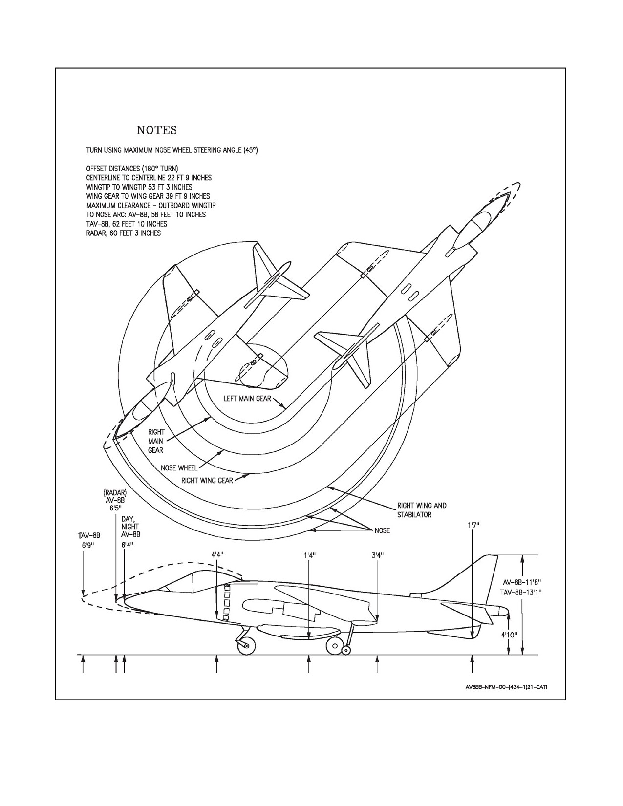
Aircraft directional control during taxi should be via nosewheel steering since no differential braking is available.
Figure 7-1 shows the turning radius using the maximum nosewheel steering angle (45°). On AV--8B 165354 and up,
the maximum nosewheel steering angle is only obtained in hi gain steering. Lo gain steering provides a turn radius
of approximately 90 feet measured at the aircraft center of gravity. Hi gain steering should be used for confined area
maneuvering only. The turn radius provided by lo gain steering should be sufficient for maneuvering on most
taxiways. FBOs and other situations requiring deliberate movement may require the use of hi gain steering. In these
situations, the pilot shall select ANTISKID to ON prior to takeoff. If the ANTISKID switch is not reset to ON, the
ensuing takeoff will not have antiskid protection. Depressing the NWS/undesignate switch will result in hi gain
steering, which is undesirable above 20 knots.
Proper steering selection technique is critical to eliminating a transient nosewheel steering output during landing
rollout. Rudder pedals should be neutralized prior to steering selection as the nosewheel steering system will
immediately moveto thecommanded rudderpedal positionwhen steeringis selected.Selecting steeringat otherthan
neutral pedals may result in a rapid heading change that may not be desirable. Also, crab angle, while on the runway,
must be eliminated or reduced as much as possible when selecting steering. Selecting nosewheel steering while
crabbed will result in an initial steering output away from the desired direction of travel.
Engagement of hi gain steering above 30 KGS may result in pilot induced
oscillation which may result in loss of directional control during landing
roll out or high speed taxi.
7-27
ORIGINAL
A1-AV8BB--NFM--000
Figure 7-1. Minimum Turn Radius and Ground Clearance
ORIGINAL
7-28
A1-AV8BB--NFM--000
If the ANTISKID/NWS switch is selected to NWS, ANTISKID is selected OFF and braking should be done carefully
to avoid tire flat spotting. If taxi speed exceeds 16 knots, ANTISKID should be selected ON and nosewheel steering
engaged by pressing and holding the NWS switch on the stick grip. Idle thrust is high and will result in excessive
taxi speed unless the brakes are used or nozzles deflected. The brakes are designed for the limited requirements of
V/STOL operationsand willoverheat easierthan onmost conventionalaircraft. Brakeenergy usagecan becalculated
using Brake Energy chart. Refer to Chapter 9, A1--AV8BB--NFM--400. If brake energy exceeds 10 × 10^ foot--pounds
hot brakes may occur.
Note
D The use of nozzle deflection between 45° and 60° for control of taxi speed
is recommended.
D If tires deflate for unknown reasons, suspect hot brakes.
When taxiing with nozzles deflected, it is essential that the stick be held forward of 2° nose down or that the stabilator
be appropriately trimmed so that the nose RCS valve will remain closed. (Since the stick will move fore and aft
slightly during taxi, the stabilator should be trimmed to 4° ND if the stick is not going to be held during taxi.) This
action will prevent the high velocity jet from the nose puffer from blowing debris into the engine intake ducts. Should
the taxi speed become too slow, the nozzles should be placed to 10° before increasing rpm above idle. If the nozzles
are stiff or fail to follow properly at idle rpm, check the nozzle operation at 36 to 40 percent rpm. If the nozzles operate
properly at 36 to 40 percent rpm, allow a short cooling period and again check nozzle operation at no more than 29
percent rpm. If the nozzles fail to operate properly at 36 to 40 percent rpm or during the second idle rpm check, abort.
Placenozzlesto10°afterstopping toavoid overheatingofmainlanding geartires andpossibledamageto thetaxiway
surface.
CAUTION
D If the nozzle angle exceeds 60°, the danger of ingestion of debris blown by
the nozzles is high and the nozzle exhaust may overheat the tires.
D ANTISKID should be selected to NWS (skid light on) in confined areas to
prevent releasing brake pressure when stopping.
Below 8 knots the antiskid is inoperative and care must be used to avoid locking the wheels, particularly at low gross
weights. There is no sensation of brake locking which will result in tire skid.
Above 8 knots the antiskid is operative and the characteristic tugging deceleration will be felt during heavy braking
as the brake pressure oscillates.
A minimum radius turn can be made only at taxi speeds below 2 to 3 knots ground speed. The radius of turn will
increase with speed and a full nose gear steering angle at relatively high speeds will heavily load the outboard wing
gear, cause a bank angle of 5° to 7° and may cause a skid as the main wheel tires lose adhesion.
Theaircraftisclearedtotaxioverasupportedarrestinggearwireuptoamaximumspeedof5knots.Stopimmediately
ifawinggearistrappedbythewire.Theaircraftmaycrossanunsupported,tensionedarrestinggearwireatanyspeed,
engine rpm or nozzle angle if the wire lies flat on the runway or deck.
When ready to taxi:
1. Master mode — V/STOL.
2. Nozzles — 10°.
3. Flaps — CRUISE.
7-29
ORIGINAL
A1-AV8BB--NFM--000
4. Trim — 0, 0, 4° ND.
5. Antiskid — CHECK.
a. Parking brake — OFF.
b. Stationary position with brake pedals — MAINTAIN.
c. ANTISKID switch — TEST.
(1) Brake relieves momentarily and aircraft moves forward. Brake returns and aircraft stops.
(2) Brake pressure drops below 110 psi as brake relieves and increases as aircraft stops.
Note
Antiskid check should be performed while chocked or when clear of other
aircraft or obstacles.
6. Brakes/NWS — CHECK.
Before AFC--391:
7. Nosewheel caster — CHECK.
Release nosewheel steering while in a turn and ensure that the nosewheel does not snap back to center.
Note
This check is the only means available to determine proper operation of the
nosewheel steering system.
TAV--8B Aircraft After AFC--391:
8. Aft Seat High Gain Override — CHECK.
a. ANTISKID Switch — NWS.
b. Front C/P NWS/Undesignate Switch — PRESS AND HOLD (NWS HI in HUD).
c. Rear C/P NWS/Undesignate Switch — PRESS.
(1) NWS HI in HUD changes to NWS.
(2) Both C/Ps NWS/Undesignate Switch — RELEASE.
d. ANTISKID Switch — ON.
7.2.1 Taxiing on Unprepared Surfaces
On loose surfaces or snow, rpm and nozzle deflection should be kept at a minimum to reduce the danger of FOD and
flaps should be in CRUISE position to prevent damage by debris.
The aircraft can be taxied on surfaces too soft to support its parked weight. Directional control is good even when
the nosewheel digs a rut. The main wheels will sink deeper than the nosewheel. Nozzle angles up to 45°may beused
to reduce sinking into soft surfaces with due regard for surface damage and FOD. RPM in excess of 70 percent with
nozzles aft or 80 percent with nozzles at 45° will cause excessive loads on bogged landing gear.
7.2.2 Sub--Idle Taxiing on Slippery Surfaces
In order to reduce engine thrust while taxiing on slippery surfaces, the throttle may be moved aft of the idle gate to
the sub--idle dwell position.
ORIGINAL
7-30
A1-AV8BB--NFM--000
CAUTION
Because of the increased possibility of engine surge occurring, this
procedure should only be used when absolutely necessary.
Note
D Minimum rpm is 20 percent (--406) or 22 percent (--408). If rpm descends
below 20 percent (--406) or 22 percent (--408) the engine must be shut down.
D MonitorJPT (535 °C max for --406 engineor545 °C max for --408 engine).
D Shall not be attempted in MFS.
D Following this procedure, the throttle shall be advanced to idle and rpm
stabilized at normal idle rpm prior to moving the throttle above the idle
gate.
7.2.3 Pre--Positioning Checks
Pre--positioning checks may be completed in the chocks, while taxiing, or while marshalling.
1.
CWAIVER checks
a. With H4.0:
CLOCK/CMBT
W -- WEAPONS PROGRAM
MENU--STORES: BOX STORE
FUZE/ARM/SOLENOID/AUTO--CCIP/Q:M:I
TONE — BOXED
SITE — SET/BOXED
IR COOL — AS REQUIRED
PROGRAM TPE: T0 -- T4
MENU--EHSD--DATA--T0
UFC: TGTS--TERM
ANG: _______
HDG: _______
REPEAT FOR T1--T4
A -- AVIONICS
TPOD
MENU--TPOD--STBY
DATA--DPFL: Note
HOLD DPFL: Note
VCR — REC
YARDSTICK: M
DESIGNATOR: D+M/LSR/TRNL/MRK
CHECK CCD/FLIR
7-31
ORIGINAL
A1-AV8BB--NFM--000
CINT/HINT
FOV: NAR, ZOOM 2
TPOD(V) FREQ: SET
APG--65
PROGRAM SETS PER MISC 1
CHANNEL SELECTED
ECCM SELECTED
GPS
MENU--BIT
ALMANAC LOADED
CRYPTO OK
H/V ERRORS CHECKED
ARC--210
MENU--COMM: LOAD TIME
CHECK AJ AS REQUIRED TO VERIFY MWOD
NAVFLIR/ARBS
BORESIGHT
FLTR/GRAY SCALES/NITE
TACAN
CARD DEFAULTS
SET L MPCD: ADMIN 4/5, BRF 1
SET R MPCD: ADMIN 1/3, BRF 2
ATHS
VERIFY NETS
MYAC SET
OSR CHECK
I -- IFF
MODE 1/2/4A: PER COMM PLN
MODE 3 AS ASSIGNED/REQUIRED
V -- VRS
RUN/AUTO
MPCD/HUD
E -- ECM
ALQ--164
BIT PROGRESS
ALE--39
CASTLE LEFT TO EW PAGE
CMDS: BOX
VERIFY LOAD/PROGRAM PER ADMIN
2 CARD
ORIGINAL
7-32
A1-AV8BB--NFM--000
ALR--67 BIT
CASTLE LEFT TO EW PAGE
RWR--RBIT: PERFORM
R -- RADALT
PUC/LAW: PER BRF 1
BOMB: PER BRF 1
b. With C1+ or OMNI 7.1:
CLOCK/CMBT
W -- WEAPONS PROGRAM
MENU--STORES: BOX STORE
FUZE/ARM/SOLENOID/AUTO--CCIP/Q:M:I
TONE: BOXED
SITE: SET/BOXED
IR COOL: AS REQUIRED
A -- AVIONICS
TPOD
MENU--TPOD--STBY
DATA--DPFL: Note
HOLD DPFL: Note
VCR--REC
YARDSTICK: M
DESIGNATOR: D+M/LSR/TRNL/MRK
CHECK CCD/FLIR
CINT/HINT
FOV: NAR, ZOOM 2
TPOD(V) FREQ — SET
APG--65
PROGRAM SETS PER MISC 1
CHANNEL SELECTED
ECCM SELECTED
GPS
MENU--EHSD--DATA--GPS
ALMANAC LOADED
CRYPTO OK
H/V ERRORS CHECKED
GPSE--BOXED
ARC--210
LOAD TIME ON RCU
CHECK AJ AS REQUIRED TO VERIFY MWOD
7-33
ORIGINAL
A1-AV8BB--NFM--000
NAVFLIR/ARBS
BORESIGHT
FLTR/GRAY SCALES/NITE
CUERS/DELTA T/TSIZE AS BRIEFED
TACAN
CARD DEFAULTS
SET L MPCD: ADMIN 4/5, BRF 1
SET R MPCD: ADMIN 1/3, BRF 2
ATHS
VERIFY NETS
MYAC SET
OSR CHECK
I -- IFF
MODE 1/2/4A: PER COMM PLN
MODE 3 AS ASSIGNED/REQUIRED
V -- VTR
RUN/AUTO
MPCD/HUD
E -- ECM
ALQ--164
BIT PROGRESS
RECV WHEN COMPLETE
ALE--39
VERIFY LOAD/PROGRAM PER ADMIN
2 CARD
ALR--67 BIT
RWR BIT — PERFORM
R -- RADALT
PUC/LAW: PER BRF 1
BOMB: PER BRF 1
2.
Canopy — CLOSED/CHECK.
a. Light out.
b. AV--8B — check viewports, physically pull back on both canopy bow handles.
If the latches are not completely down and seated (canopy properly closed),
orange alignment lines will not be aligned and canopy failure in flight may
occur.
ORIGINAL
7-34
A1-AV8BB--NFM--000
Note
Physically pulling back on both canopy bow handles only ensures the
canopy is latched on one side due to the rigidity of the canopy frame.
c. TAV--8B — push up on canopies without disturbing MDC and check canopy misalignment marker.
3. Seat — ARMED.
4. Flight and standby instruments — CHECK.
5. APU — AS DESIRED.
6. ANTISKID — ON (LIGHT OUT).
7. VTR — RUN.
8. Abort #’s — CHECK.
9. Altitude Switch — AS DESIRED.
10. INS Knob — IFA/NAV.
11. Approach Light — ON.
12. Rudder pedal shaker — CHECK.
While taxiing place RPS switch to TEST and make left and right turns with nosewheel steering. The rudder pedal
shaker activates when the sideslip ball reaches its limits. During left turns the ball moves right and activates the right
rudder pedal shaker. During right turns the ball moves left and activates the left rudder pedal shaker.
7.3
TAKEOFF
Four methods of takeoff are possible. These are Vertical Takeoff (VTO), Rolling Vertical Takeoff (RVTO), Short
Takeoff (STO) and Conventional Takeoff (CTO). The method of takeoff is dependent upon tactical and other
conditions and must be predetermined in order to perform the necessary calculations and properly configure the
aircraft. Refer to Performance Data, A1--AV8BB--NFM--400, Mission Planning System (MPS), or the Mission
Computer VREST calculator in order to determine required takeoff parameters. For crosswind takeoff techniques
and considerations, refer to Chapter 11, Crosswind Takeoff Operations.
7.3.1 Takeoff Checklist
The following takeoff checklist is used to configure the aircraft for all four takeoff methods. Although it is suitable
for use in a wide variety of operating conditions, no single checklist can be written to encompass all types of austere
operating conditions. Certain environmental conditions (i.e. ice, snow, FOD, etc.) may require modification of the
established take off checklist as it may not be safe to accomplish items such as acceleration or nozzle checks while
the aircraft is stationary. Prudence dictates that a modified checklist be practiced, preferably in a simulator, before
deployment to a site requiring its use. If conditions prohibit certain checks from being completed, operational
necessity of the flight must be considered before continuing.
Note
Each aircraft cockpit contains a takeoff checklist placard. The content of
these placards varies substantially from the takeoff checklist described in
this manual.
The Takeoff Checklist consists of two parts. During the first part the aircraft is placed in the proper configuration.
This configuration check is referred to as a One Finger check because it is initiated and confirmed by signaling with
7-35
ORIGINAL
A1-AV8BB--NFM--000
the index finger extended. During the second part of the takeoff checks, the pilot evaluates engine performance, flap
programming and nozzle movement, as well as arming the water system, if required. This check is referred to as a
Two Finger or Five Finger check depending on whether or not water is being used. Once the check is complete, the
pilot indicates preparation for a dry takeoff by signaling with two extended fingers. If the takeoff will be wet, then
five fingers are extended.
Pitch carets (PC)areset at 14 forall takeoffs. This places thepitch carets at 6°of elevation with respect to thehorizon
bars in the V/STOL Master Mode. This position indicates the desired post--takeoff placement of the Depressed
Attitude Symbol (or Witches Hat). This takeoff attitude is the level--flight equivalent of 14° AOA. Trim for takeoff
shall be 0° for both aileron and rudder. Shore--based pitch trim shall be 2° ND except when conducting a VTO in the
TAV--8B, in which case 1° ND will be used. These trim settings are based upon rotation of the aircraft/nozzles at the
calculated rotation airspeed while the stick remains guarded at the trimmed position. Use of additional airspeed in
order to provide a performance pad will produce nose down pitching moments after rotation that will have to be
arrested with aft stick deflections. Configuration of the NRAS, STO STOP, flaps and water, as well as movement
of the nozzles during the flight control check, will vary depending on the type of takeoff being performed. Refer to
specific takeoff procedures for additional detail.
Configuration Checks (One Finger Checks):
1. Nozzle Rotation Airspeed (NRAS) — AS REQUIRED.
Press V/STOL master mode button. Select NRAS option on ODU. Insert NRAS on the UFC.
2. Pitch Carets (PC) — SET.
Select PC on ODU. Insert 14 on UFC.
3. STO Stop — AS REQUIRED.
4. Trim — SET.
5. Flaps — AS REQUIRED.
6. Warning/caution lights — OUT.
On aircraft after AFC--391
(NWS Mod), it is imperative that the
ANTISKID switch be reset to ON prior to completion of takeoff checks.
Failure to do so will result in the loss of antiskid protection on the ensuing
takeoff and will additionally result in the unintended selection of hi gain
steering if the NWS button on the stick is depressed and held with throttle
below about 75 percent fan speed.
Engine, Water System and Flight Control Checks (Two/Five Finger Checks):
7. Engine — CHECK.
a. DDI — Select Eng/Box Accel.
b. Accelerate engine from idle to 55 percent (--406) or 60 percent (--408).
c. Check acceleration time within limits: --406 engine 27 to 55 percent in 3.7 to 4.3 seconds. --408 engine 35
to 60 percent in 2.4 to 3.1 seconds.
d. IGVs — check scheduling and verify in the band of 8° to 19° at 55 percent (--406) or 10° to 21° at 60 percent
(--408).
ORIGINAL
7-36
A1-AV8BB--NFM--000
e. (--408A or --406 engine only) Record IGV angle from Engine page and plot on card (Figure 7-2) in relation
to ambient temperature to ensure IGV angle is within the boundaries depicted on card. If the IGV angle is
outside the boundary lines abort the flight and report the anomaly to maintenance personnel.
CAUTION
Abnormal engine accelerations under DECS control, regardless of fuel
type, OAT or density altitude are indicative of either a degraded engine or
engine control system.
8. Water — AS REQUIRED.
a. Place water switch to TO and note RPM rise.
b. Reset RPM to top end of acceleration band.
9. Nozzle/flaps/duct pressure — CHECK.
a. Set nozzles momentarily to STO stop (or 50° if STO stop is not required).
b. Check flaps for proper angle based on flap mode.
c. Check duct pressure approximately 45 psi.
d. Place nozzles at the takeoff position.
7.3.2 Jetborne/Semi--Jetborne Takeoffs
All jetborne and semi--jetborne takeoffs begin with a takeoff procedure and end with an accelerating transition to
wingborne flight. Conceptually, the transition point between the takeoff procedure and the accelerating transition
procedure begins once the aircraft is off the ground, the wings are level and the vane is centered. At this point, attitude
(and AOA) can be safely increased and the Accelerating Transition (7.3.2.4) can begin.
7.3.2.1 Vertical Takeoff
If possible, VTO into the wind. Lateral control during the first few feet of a VTO is critical. Do not hesitate to make
immediate, large and rapid control movements to counteract bank angles.
Configuration Checks (One Finger Checks):
1. Nozzle Rotation Airspeed (NRAS) — NOT REQUIRED.
2. Pitch Carets (PC) — SET.
3. STO Stop — CLEAR.
4. Trim — SET.
5. Flaps — STOL.
6. Warning/Caution Lts — OUT.
Engine, Water System and Flight Control Checks (Two/Five Finger Checks):
7. Engine — CHECK.
8. Water — AS REQUIRED.
7-37
ORIGINAL