NATOPS FLIGHT MANUAL NAVY MODEL AV--8B/TAV--8B 161573 AND UP AIRCRAFT (2008) - page 3
A1-AV8BB--NFM--000
2.17.7 Antiskid System
The antiskid system is an electro--hydraulic system that controls hydraulic pressure to the brakes providing full skid
protection above 16 knots. The system also provides partial skid protection from 16 knots down to 8 knots. An
impending skid is detected by measuring wheel deceleration. Wheel speed information is provided by a wheel speed
sensor, located on the right brake unit, and an exciter ring mounted on the wheels. As the exciter ring rotates, the
sensor develops an electrical signal at the frequency of the wheel speed. This signal is routed to a control unit which
develops and transmits a signal to operate the antiskid valve. The antiskid valve, when operating in conjunction with
the control unit, relieves brake pressure to arrest tire skid.
Theantiskid system is selected by theANTISKID switchlocated onthelandinggear/flaps controlpanel (fwdcockpit
only). The switch is labeled TEST, ON, and NWS. Power is not supplied to the antiskid system when NWS is
selected. A SKID light, on the caution light panel, comes on when the antiskid system is OFF or failed, providing
essential 28 volt dc power is available.
2.17.7.1 Skid Caution Light
On AV--8B 161573 through 165312, TAV--8B, the SKID light also comes on when a nosewheel castering failure is
detected. On the TAV--8B, the SKID light comes on in both cockpits. See nosewheel steering this chapter.
The TEST position on the ANTISKID switch, allows the pilot to check the antiskid system. Antiskid is inoperative
when the parking brake is engaged or essential 28 volt dc power is lost.
2.18
INSTRUMENTS
Refer to foldout section for cockpit instrument panel illustration. For instruments that are an integral part of an aircraft
system, refer to that system description in this section.
2.18.1 Pitot Static System
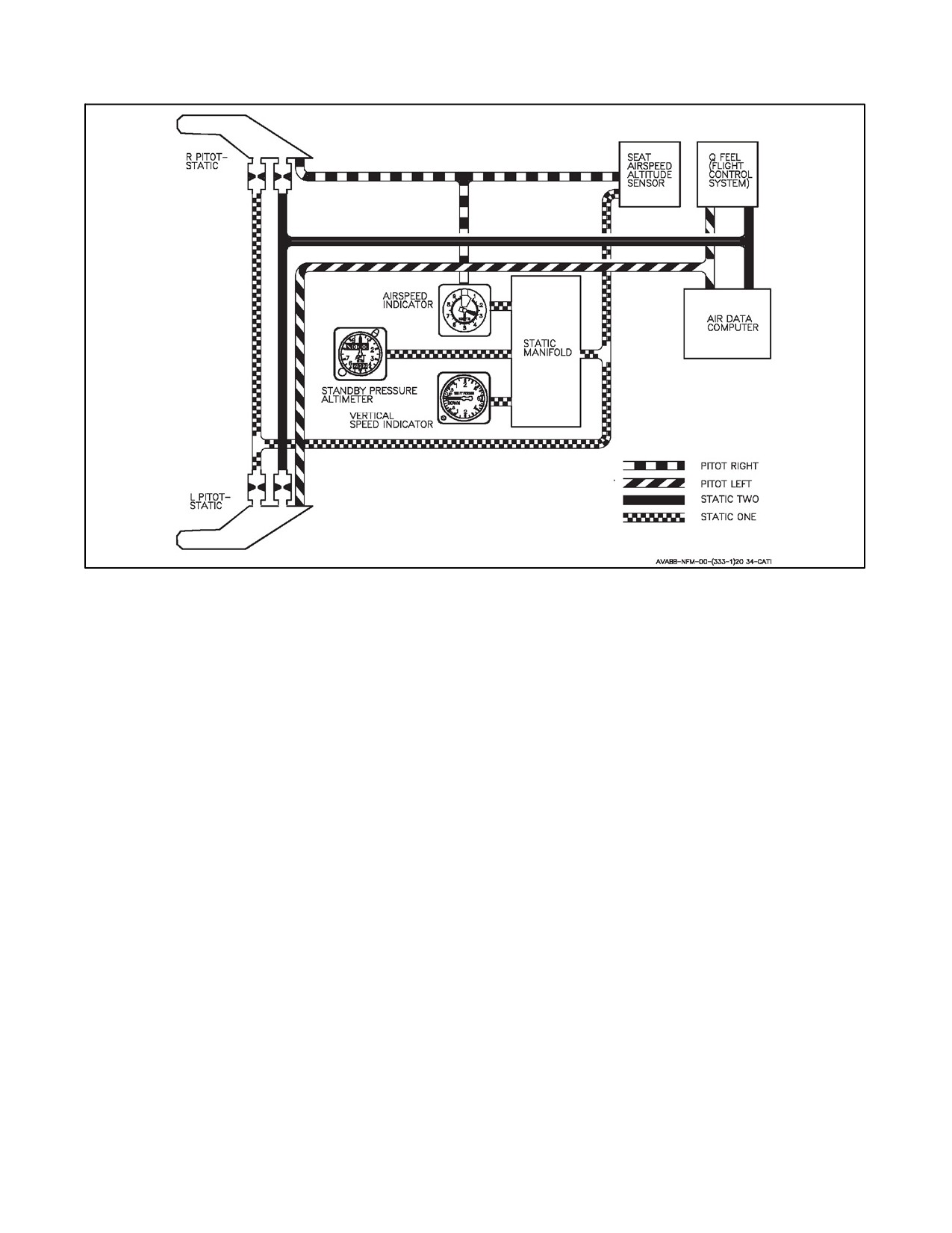
The pitot--static system employs dual pitot and static sources, one on each side of the forward fuselage near the leading
edge of the windshield. Each tube contains one pitot source and two static sources. See Figure 2-18.
2.18.1.1 Probe Heat Switch
The probe heat switch on the miscellaneous switch panel on the lower main instrument panel has positions PRB HT
(PROBE HEAT on some aircraft) and AUTO. The switch controls power to the left and right pitot--static probes, the
totaltemperatureprobe,thecaseandprobeheateroftheangleofattackprobe,andtheDECStotaltemperatureprobes.
AUTO - With weight on wheels, power is removed from all heaters except AOA case heater. With aircraft
airborne, all probe heaters receive power.
PRB HT - With weight on wheels, all heaters are energized but the left and right pitot static probes are
energized at reduced power. With aircraft airborne, all probe heaters receive power same as AUTO. The switch
is magnetically held in the PRB HT position. When power is removed, the switch drops into the AUTO
position.
2.18.1.2 Pitot Pressure
Pitotpressurefromtheleftpitot--staticprobeissuppliedtotheairdatacomputerandtheQ--feelsystem. Pitotpressure
from the right pitot--static probe is supplied to the standby airspeed indicator and the ejection seat airspeed/altitude
sensor.
2.18.1.3 Static Pressure
One static source from each pitot--static tube are tied together and the pressure is routed to the air data computer and
the Q--feel system. The other static source from each pitot--static tube is tied together and the pressure is routed to
the pressure--operated standby indicators and the ejection seat airspeed/altitude sensor.
ORIGINAL
2-62
A1-AV8BB--NFM--000
Figure 2-18. Pitot--Static System
2.18.2 Angle of Attack Probe
The angle of attack probe is an airstream direction sensing unit. The probe is located on the right forward fuselage
below the windshield except on radar aircraft where it is located on the left forward fuselage below and forward of
the windshield. It contains a case heater and a probe heater, operation of which is covered under Probe Heat Switch
in Instruments procedures. The standby angle of attack indicator and the air data computer utilize signals from the
angle of attack probe.
2.18.3 Standby Angle of Attack Indicator
The standby angle of attack (AOA) indicator (see cockpit, foldout section) is on the main instrument panel. The
indicator is calibrated from --5° to +25° An adjustable reference index two degrees wide is centered on the 10° mark
to indicate optimum speed approach angle of attack. When electrical power is interrupted, the word OFF appears in
a window in the face of the indicator.
2.18.4 Turn and Slip Indicator
The turn and slip indicator contains a scale, turn pointer, power warning flag and inclinometer ball. A 2--minute turn
is indicated with the needle over the index to the left and right of center. A 4--minute turn is indicated with the needle
half way between the center and the right or left index. The gyro is driven by an inverter, which is powered from the
emergency 28 volt dc bus. An OFF flag is provided to indicate loss of power.
2.18.5 Clock
Astandard8dayclockisinstalledinthecockpitandontheTAV--8BintherearcockpitpedestaladjacenttotheBUNO
PLACARD.
2.18.6 Stopwatch
A mechanical stopwatch is located to the left of the glareshield near the canopy rail (not in rear cockpit of TAV--8B).
The stopwatch contains one pushbutton for winding, starting, and stopping and one pushbutton for resetting.
2-63
ORIGINAL
A1-AV8BB--NFM--000
2.18.7 Standby Magnetic Compass
A conventional aircraft magnetic compass is installed to the left of the main instrument panel (not installed in the
rear cockpit). The standby magnetic compass is installed on the left archway.
2.18.8 Standby Vertical Velocity Indicator
The standby vertical velocity indicator displays rate of ascent or descent on a scale from 0 to 6,000 feet per minute.
2.18.9 Standby Attitude Indicator
Thestandbyattitudeindicatorisaself--containedelectricallydrivengyro--horizontypeinstrument.Thegyroisdriven
by an inverter which is powered by the emergency 28 volt dc bus. An OFF flag appears whenever power is lost or
the unit is caged. The gyro cages to 0° pitch and roll regardless of aircraft attitude. Power should be applied for at
least 1 minute before caging. The indicator displays roll through 360°. Pitch display is limited by mechanical stops
at approximately 92° climb and 78° dive. The caging knob on the lower right hand corner, besides being pulled for
caging, is used to adjust the pitch of the miniature aircraft. A pitch--trim scale measures displacement of the miniature
aircraft. Pulling the caging knob and rotating fully clockwise to a detent locks the inner gimbal of the gyro. This
position is for storage and transport, and should never be used during flight. A minimum of 9 minutes of reliable
attitude information (error less than 6°) is available after power loss, even though the OFF flag is in view.
2.18.10 Standby Altimeter
The standby altimeter displays altitude from --1,000 feet to 50,000 feet. The altimeter is a counter--pointer type. The
counter drum indicates altitude in thousands of feet from 00 to 99. The long pointer indicates altitude in 50 foot
increments with one full revolution each 1,000 feet. A knob and window permit setting the altimeter to the desired
barometer setting. This setting is also used by the air data computer. An electrical altimeter vibrator is provided to
insure smooth travel of the internal mechanism.
Note
The standby altimeter may indicate in excess of 400 feet low at high
airspeeds.
2.18.11 Standby Airspeed Indicator
The standby airspeed indicator displays airspeed from 20 to 600 knots. The indicator contains two pointers and a
singlescalegraduatedfrom1 through10. Thepointers appearonly oneat atime. Atlow airspeedsthescalerepresents
0 to 100 knots and the thin pointer indicates the airspeed. At higher airspeeds the scale represents 100 to 1,000 knots
and the thick pointer indicates the airspeed. However, the thick pointer will not proceed beyond the 600 knot
indication.
2.18.12 Horizontal Situation Indicator
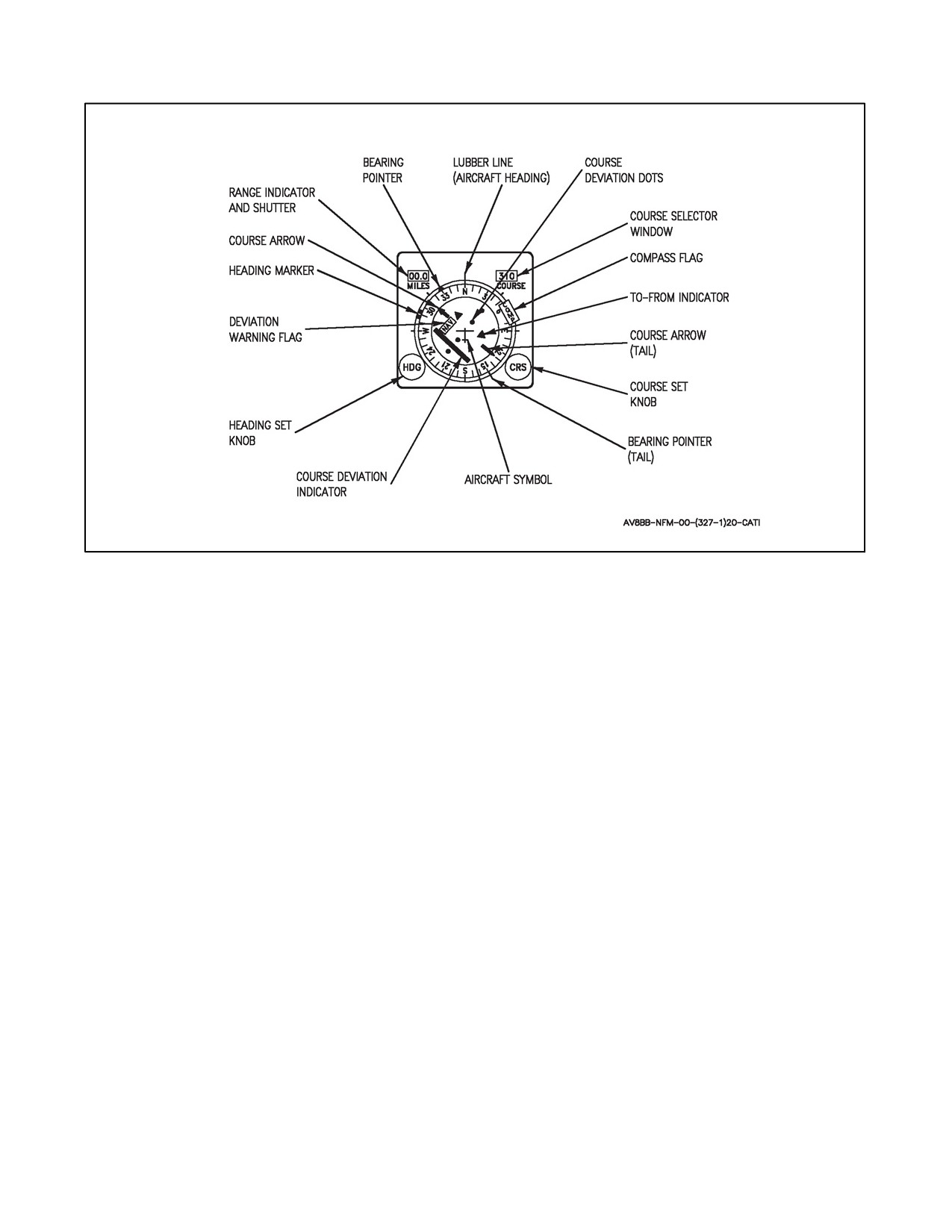
On TAV--8B and Day Attack aircraft the horizontal situation indicator (HSI) (see Figure 2-19) is on the main
instrument panel. The HSI provides horizontal or plan view of the aircraft with respect to the navigation situation.
The knobs, pointers, windows, and flags which are on the HSI are described in the following paragraphs.
2.18.12.1 Aircraft Symbol
The aircraft symbol in the center of the HSI is the aircraft superimposed on a compass rose.
2.18.12.2 Aircraft Heading
The aircraft magnetic heading is read under the lubber line.
2.18.12.3 Heading Marker
The heading marker is manually set to the desired heading.
ORIGINAL
2-64
A1-AV8BB--NFM--000
Figure 2-19. Horizontal Situation Indicator
2.18.12.4 Course Arrow
The course arrow and the course selector window are set manually with the course set knob to the desired tacan course.
2.18.12.5 Course Deviation Indicator
Any displacement of the aircraft from the selected course causes the course deviation bar to move to the right or left
of the course arrow.
2.18.12.6 Bearing Pointer
The bearing pointer displays the bearing to a selected tacan station. The bearing tail indicates reciprocal course.
2.18.12.7 Range Indicator
Distance is displayed in nautical miles and has a range of 00.0 to 399. A shutter will cover the window if distance
information is invalid.
2.18.12.8 To--From Indicator
The to--from indicator indicates whether the course selected, if intercepted and flown, takes the aircraft to or from
the selected tacan station.
2.18.12.9 Deviation Warning Flag
The flag is in view when the bearing data is invalid.
2.18.12.10 Compass Flag
The flag is in view when the compass data is invalid.
2.18.12.11 Course Set Knob
The knob, labeled CRS, is used to set a predetermined course to be steered to a tacan station, all weather landing
system (AWLS) station, or steer--to--point (waypoint, markpoint, or targetpoint).
2-65
ORIGINAL
A1-AV8BB--NFM--000
CAUTION
The course line displayed on the EHSI/EHSD and the course in the Course
Selector Window of the HSI is not necessarily the same. The bearing
displayed in the Course Line Data block in the lower right corner of the
EHSI/EHSD and the course line displayed on the EHSI/EHSD should be
used instead of the bearing in the Course Selector Window of the HSI.
Note
With OMNI 7.1 and C1+, a predetermined course cannot be used to steer
to an AWLS station or a targetpoint.
2.18.12.12 Heading Set Knob
The heading set knob, labeled HDG, is used to set the heading marker to a desired heading. If the knob is pulled out,
the compass is disabled and the compass flag comes into view. Ensure the knob is pushed in fully.
2.18.13 Sideslip Vane
A sideslip vane is mounted externally forward of the windshield for use during slow or hover flight. It always points
intotherelativewind.Therearcockpitsideslipvaneismountedonthecentertopofwindshieldarchframe,externally.
2.18.14 Radar Altimeter
The radar altimeter indicates surface clearance directly under the aircraft from 0 to 5,000 feet up to pitch and roll
attitude of ±45°. Operation is based on precise measurement of time required for an electro--magnetic energy pulse
to travel from the aircraft to the ground terrain and return. Audio and visual warnings are activated when the aircraft
is at or below a selected low altitude limit. When target of opportunity (TOO) function is engaged on the upfront
control, the radar altimeter is turned on momentarily and the radar altitude is used by the mission computer to
determine target elevation. The radar altimeter also has an update function available to adjust barometric altimeter
error for mission computer navigation and air--to--ground calculations.
2.18.14.1 Controls and Indicators
The controls and indicators for operation of the radar altimeter are on the HUD, warning/threat lights panel, upfront
control, option display unit and digital display indicator (DDI).
2.18.14.2 Altitude Switch
The ALT switch, on the HUD control panel, has positions of barometric (BARO) and radar (RDR). When the switch
is set to RDR, radar altimeter altitude preceded by an R is displayed in a box in the upper right hand part of the HUD
display. In BARO, barometric altitude is displayed without theR in the box. If radaraltimeter altitudeis invalid with
switch in RDR, the R disappears and a flashing B appears to the right of the box indicating barometric altitude is being
displayed. The flashing B remains until either radar altitude becomes valid again or the altitude switch is placed to
BARO. In the backup mode, barometric altitude replaces radar altitude but will not flash. This switch is
non--functioning in the rear cockpit. With H4.0, the box around the altitude is no longer displayed.
2.18.14.3 Low Altitude Warning Light
The Low Altitude Warning (LAW) light is located on the warning/threat light panel on the upper right of the instrument
panel. If the system is operational and the aircraft descends below the preset low altitude threshold (0 to 5,000 feet above
surface level) the LAW light will come on. The mission computer requires at least three radar altimeter returns above the
threshold altitude to subsequently trigger the LAW during descent. Due to aircraft maneuvers during ascent or descent,
variances in transmitter and receiver capabilities, or mountainous terrain, LAW thresholds above 4,500 feet may be
ORIGINAL
2-66
A1-AV8BB--NFM--000
unreliable. The LAW light will stay on until the aircraft ascends above the low altitude threshold, the pilot changes
the low altitude warning threshold, the radar altimeter is turned off, or the MASTER CAUTION (or MASTER
WARNING light button on Radar or Night Attack aircraft) light button is pressed. The MASTER CAUTION shutoff
function resets when the aircraft ascends above the threshold altitude. With loss of the mission computer, the LAW
light automatically operates at 200 feet above ground level. To eliminate false LAW indications with speed brake
extended, radar altitude is invalid with gear handle up and radar altitude less than 20 feet. On TAV--8B 163856 and
up, AV--8B 163519 and up, an ALTITUDE, ALTITUDE voice warning is provided in conjunction with the LAW
light.
CAUTION
LAW thresholds above 4,500 feet greatly reduce the probability of the
LAW being triggered during descent.
2.18.14.4 Upfront Control
The pushbuttons and indicators on this control are used for radar altimeter operation and display, to select altitudes
for LAW light operation, and also to enable the BOMB option.
2.18.14.4.1 Altitude Function Selector Pushbutton
Pressing the altitude (ALT) function selector pushbutton enables the status window on the scratch pad to display ON
if radar altimeter is turned on, and enables display of the LAW threshold altitude on the scratch pad when set in by
the keyboard. The display on the scratch pad indicates the altitude that the LAW light will illuminate and the LAW
warning tone or ALTITUDE, ALTITUDE voice warning will activate. Pressing the ALT pushbutton also enables
display of BOMB on the option number 1 display window on the option display unit.
2.18.14.4.2 On/Off Selector Pushbutton
Pressing this pushbutton turns the radar altimeter system on after first pressing the ALT function selector pushbutton.
This causes ON to appear on the scratchpad of the upfront control. To turn the system off the ON/OFF selector
pushbutton is pressed after first enabling the altitude function with the ALT function selector pushbutton.
2.18.14.4.3 Scratchpad and Keyboard
With the ALT function enabled, the LAW altitude is displayed in the scratchpad window. A new LAW altitude is
inserted by typing out the new altitude and then pressing the ENT pushbutton on the keyboard.
2.18.14.4.4 EMCON Pushbutton
Pressing the emission control (EMCON) pushbutton enables the EMCON functionality and EMCN is displayed in
the Options Display Unit (ODU) number 1 display window. Pressing the EMCON pushbutton again disables the
EMCON functionality and EMCN is removed from the ODU. With H4.0 EMCON can also be enabled or disabled
by pressing down and holding the Sensor Select switch on the control stick for greater than 0.8 seconds. When
EMCON is enabled, the RADAR, RADALT, IFF, and TACAN are inhibited. With H4.0, EMCON is overridden by
the RADALT if the pilot connects a TOO or WOF.
2.18.14.4.4.1 Head--Up Display
EMCONshallbedisplayedin themiddleoftheHUDas anindication thatEMCON isON. Itwill displayin allmaster
modes and all of the reject levels.
2.18.14.5 Option Display Unit
The pushbuttons and displays on this panel which affect operation of the radar altimeter are option select pushbutton
number 1 and option number 1 display window. They are used to enable the BOMB function.
2-67
ORIGINAL
A1-AV8BB--NFM--000
2.18.14.5.1 Option Number 1 Pushbutton and Display Window
With the ALT function selector switch pressed, BOMB is displayed in the option number 1 display window. With
the radar altimeter operating, pressing the option number 1 pushbutton causes a colon to be displayed to the left of
BOMB on the option number 1 display window. The colon indicates that radar altitude is being used by the mission
computer for ballistic computations. The last selected LAW altitude remains in the scratchpad window after the
BOMB option is selected. With weight on wheels the system will initialize to BOMB option enabled so that radar
altitude will be used for ballistic computations unless radar altitude becomes invalid. Pressing the option number 1
pushbutton again removes the colon from BOMB on the option number 1 display window and enables GPS altitude
for ballistic computations if GPS is cued. Otherwise, barometric altitude is used for ballistic computations.
2.18.14.6 DDI Display
Radar altitude is displayed on the DDI when dual mode tracker air--to--ground (A/G) video, forward looking infrared
(FLIR), air--to--air (A/A) radar or air--to--surface (A/S) radar program video is displayed, RDR is selected on the HUD
control panel, and the radar altimeter is within operational parameters.
2.18.14.6.1 Radar Altimeter BIT Checks
To perform a radar altimeter BIT check, press the BIT pushbutton on the DDI menu display to initiate a BIT display.
Press the CNI pushbutton and the word TEST appears next to RALT. After 5.5 seconds the word TEST disappears.
Check LAW light off, and LAW and MASTER CAUTION tones in headset for one second. If a number 1 appears
next to RALT the radar altimeter has failed the BIT check. If the space next to RALT remains blank the radar altimeter
has checked good.
2.18.15 Upfront Control
The pushbuttons and indicators on this control are used for entering (ENT) or clearing (CLR) data (i.e. 0--9, .,--) for
theselectedfunction.(InTAV--8Baircraft),therearetwoUFCSs,oneintheforwardcockpitandoneintheaftcockpit.
If only one UFCS (forward or aft) is being used to enter data, the system shall accept data entry from that UFCS and
cause that data to be displayed on both the entry UFCS and the non--entry UFCS as the entry is taking place. In the
event of entries occurring on both UFCSs simultaneously, the system shall cause each UFCS to display its own entry
as long as neither entry is completed. As soon as the first entry is completed, the data shall be displayed on both
UFCSs.
Note
D If the first key is to be an alpha instead of a numeric, the first pilot to enter
an alpha key will get the result as an alpha. The second pilot will get a
number, which will result in an invalid entry.
D If the data format contains only one decimal point (a Comm frequency is
an example), only the first pilot to enter a decimal point will get the decimal
point.
2.18.16 Digital Display Indicator and/or Multipurpose Color Display
The digital display indicator (DDI), on the left main instrument panel on Day attack (TAV--8B and AV--8B Day
Attack) aircraft or the multipurpose color display (MPCD), on either side of the main instrument panel (Radar and
Night Attack aircraft), are the primary aircraft head down displays. They consist of a 5 by 5--inch CRT display
surrounded by 20 multi--function pushbutton switches. DDI/MPCD mode selection is accomplished either
automatically, as determined by the mission computer, or manually, as selected by the pilot on the DDI/MPCD or
by the hands on throttle and stick (HOTAS). The display computer converts information received from the mission
computer to symbology for display on the DDI/MPCD. Some of the displays options are: MENU, stores status
(STRS), head--up display (HUD), engine parameters (ENG), electronic horizontal situation indicator/display
(EHSI/EHSD), dual mode tracker (DMT) (trainer, day attack, and night attack only), built--in--test (BIT),
VSTOL--REST (VRST), and electronic countermeasures/warfare (ECM/EW). Additionally, in the Radar and Night
ORIGINAL
2-68
A1-AV8BB--NFM--000
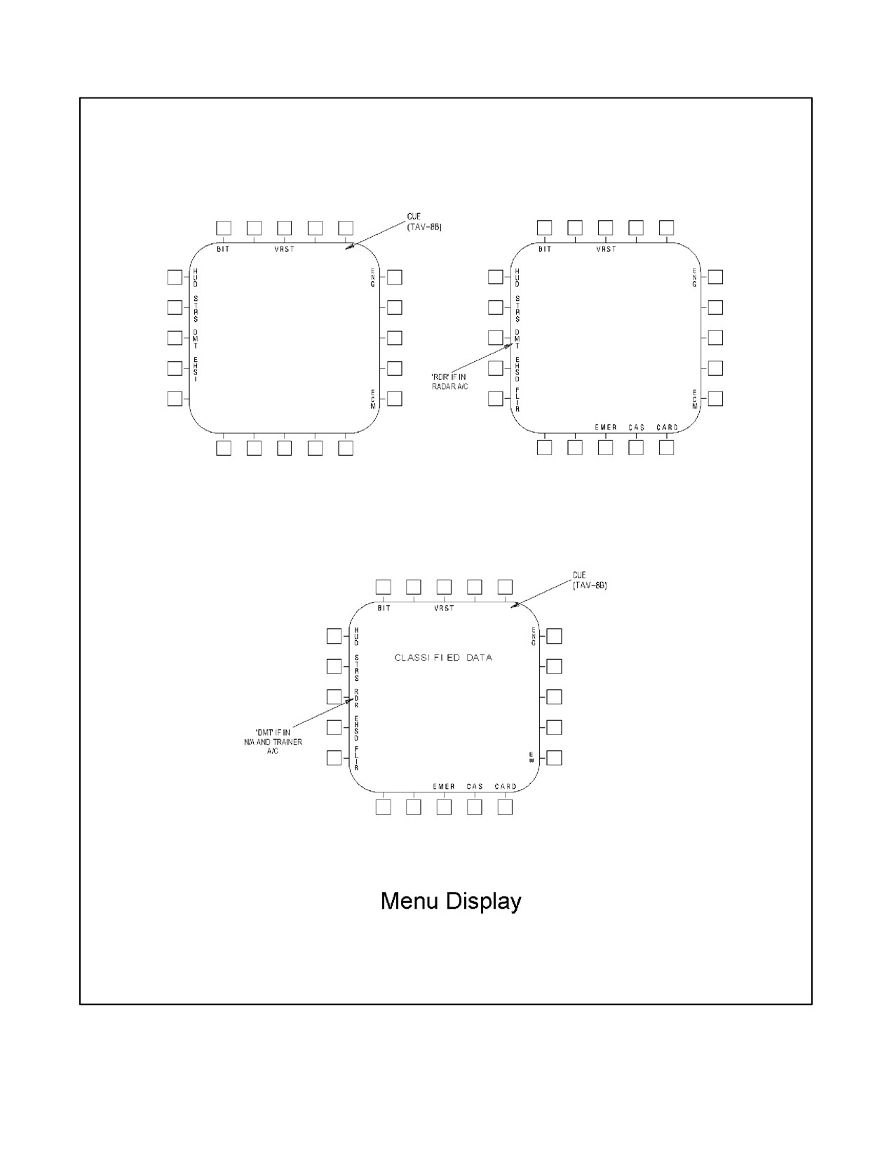
Attack Aircraft (and Trainer aircraft with H4.0), four other pushbuttons are available, FLIR-- when boxed the
NAV/FLIR image is displayed on the MPCD; EMER-- when boxed the emergency checklist menu page is displayed;
CARD-- when boxed the pre--programmed kneeboard cards are displayed; and CAS-- when boxed the close air
support page is displayed. With H4.0 four other pushbuttons are available; CONF-- when boxed the software
configuration page is displayed; TPOD-- when boxed the Litening Pod video page is displayed; SDAT-- when boxed
the system data page is displayed; and COMM-- when boxed the COMM data page is displayed, see Figure 2-20,
Menu Display. The display options are selected by pressing the MENU pushbutton (center bottom pushbutton). The
word MENU is displayed above the center bottom pushbutton for all displays except the MENU display itself and
multipurposedisplay (MPD)test pattern. Useofthevarious displays aredescribed in otherparts ofthe manual where
the affected system(s) is covered.
Note
The display computer in TAV--8B aircraft with OMNI 7.1 does not display
the same page on the front and rear cockpit DDIs at the same time (other
than the MENU page). TAV--8B aircraft with H4.0 display the same page
on both the front and rear cockpit DDIs.
2.18.16.1 DDI Switches and Controls
A description of the various switches and controls are discussed in the following paragraph.
2.18.16.1.1 Brightness Selector Knob
This rotary knob is at the top of the DDI. Placing the knob to OFF prevents the indicator from operating. Placing the
knob to NIGHT provides a lower brightness control range and no automatic contrast control. The knob in the AUTO
position allows automatic brightness control circuits to compensate display brightness for changes in ambient
lighting. Turning the knob to DAY provides higher brightness control range with no automatic contrast control.
2.18.16.1.2 Brightness Control
This knob varies the intensity of the presentation.
2.18.16.1.3 Contrast Control
This knob varies the contrast between symbology and the dark background on any level of brightness.
2.18.16.1.4 Pushbuttons
There are 20 pushbuttons on the DDI which are used to select the function and the mode for proper indicator display.
2.18.16.2 MPCD Switches and Controls (Before ECP 306)
There are four two--position rocker switches on the MPCD for display control. A description of the various switches
on the MPCD follows.
2.18.16.2.1 DAY/AUT Switch
The day position of this switch turns the MPCD on and places it in the normal day operating mode. The AUT
(automatic) position turns the MPCD on and selects the auto mode which automatically changes brightness levels
to maintain a fixed contrast ratio based on outside ambience.
2.18.16.2.2 OFF/NGT Switch
The NGT (night) position of the OFF/NGT switch turns the MPCD on and selects the night operating mode. The
OFF position turns the MPCD off.
2.18.16.2.3 BRT Switch
The BRT rocker adjusts the brightness of the display. The switch has a position feedback reference number indication
on the display, which helps match one display to the other, providing consistent image brightness, when the display
alternate toggle (DAT) function is used. The number is automatically removed after a few seconds. The BRT switch
is inoperative with an EHSD display.
2-69
ORIGINAL
A1-AV8BB--NFM--000
TAV-8B WITH OMNI 7.1
RADAR AND NIGHT ATTACK
AND DAY ATTACK AIRCRAFT
AIRCRAFT WITH C1+
TAV-8B, RADAR AND NIGHT
ATTACK AIRCRAFT WITH H4.0
C
O
N
F
T
P
O
D
COMM SDAT
Figure 2-20. Menu Display
ORIGINAL
2-70
A1-AV8BB--NFM--000
2.18.16.2.4 CONT Switch
The CONT rocker switch adjusts the contrast level of the display. This switch also has the position feedback reference
number indication. Independent contrast settings for color and monochrome displays are stored in the MPCD.
2.18.16.2.5 Pushbuttons
There are twenty pushbuttons on the MPCD which are used to select the function and the mode for proper indicator
display.
2.18.16.3 Digital Display Indicator (TAV--8B)
The displays on the DDIs in both cockpits are always the same. Both DDIs may be switched on from either cockpit,
however, the brightness selector knob on each DDI must be placed to OFF to prevent both DDIs from operating. The
last selection made in either cockpit with the perimeter pushbuttons determines the function selected for both. With
the front cockpit DDI power switch in NIGHT, AUTO, or DAY, changing the position ofthe rearcockpit DDIpower
switch causes a momentary blooming effect on the rear cockpit display.
2.18.17 Multipurpose Color Display (After ECP 306)
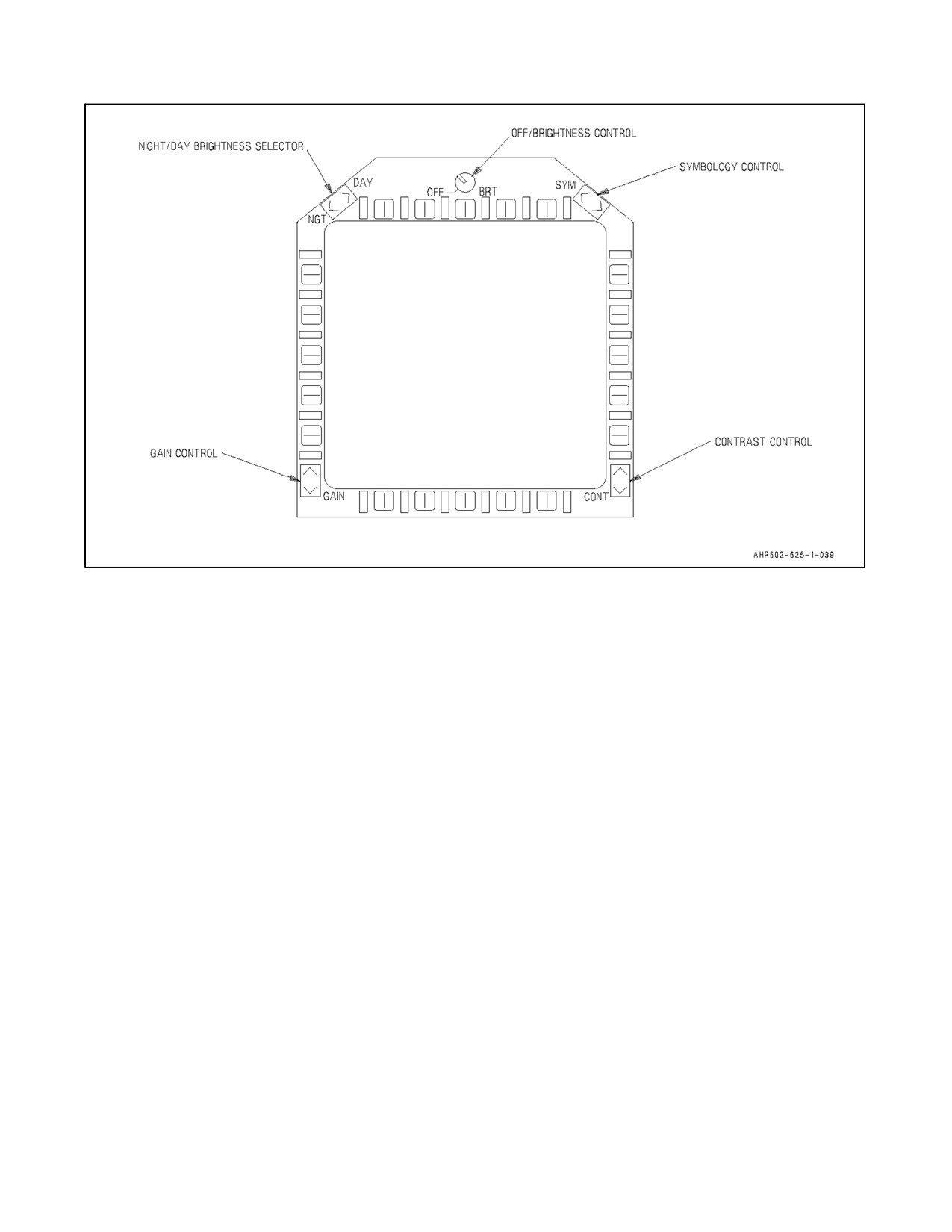
The MPCD (Figure 2-21) is an NVG compatible digital display. Four momentary two position rocker switches and
a rotary knob, located on the front of the MPCD, permit control of MPCD off/brightness, night/day viewing modes,
symbology, gain, and contrast.
2.18.17.1 OFF/BRT Control
This rotary switch is located in the upper center of the MPCD and is used to turn the MPCD off (OFF position
selected) or to select the brightness level.
2.18.17.2 NGT/DAY Brightness Selector
This rocker switch is located in the upper left corner of the MPCD and is used to select the lower brightness control
(night) range and (NGT position selected) or to select the higher brightness control (day) range (DAY position
selected). When NGT is selected, the display is NVG compatible. In either NGT or DAY, the display may be manually
adjusted with the CONT, GAIN and SYM controls.
2.18.17.3 SYM Control
This rocker switch is located in the upper right corner of the MPCD. Momentary actuations of the lower half of the
switch incrementally narrows the stroke symbology, making it sharper and dimmer. Momentary actuations of the
upperhalfincrementally widens thestrokesymbology,making itbrighterandless sharp.Iftheswitch isheld ineither
position, the symbology is continuously adjusted to the upper or lower limits. The current level of the SYM control
is displayed near the CONT switch. The range is from 0 to 15. Examples of stroke symbology are the MENU format
or the pushbutton legends on the FLIR format.
2.18.17.4 GAIN Control
This rocker switch is located in the lower left corner of the MPCD. Momentary actuations of the upper half of the
switch incrementally increases the black level of the sensor video and raster symbology. Momentary actuations of
the lower half incrementally decreases the black level of the sensor video. If the switch is held in either position, the
gain is continuously adjusted to the upper or lower limits. The current level of the GAIN control is displayed next
to the GAIN switch when it is depressed. The range is from 0 to 15. The GAIN control is active on the EHSD page
when the Map is selected even though the GAIN setting is displayed as an X when depressed. Examples of raster
symbology aretheEHSD format ortheairspeed and altitude on the FLIR format. Examples of sensorvideo areFLIR
and Map.
2-71
ORIGINAL
A1-AV8BB--NFM--000
Figure 2-21. Multipurpose Color Display (After ECP 306)
2.18.17.5 CONT Control
This rocker switch is located in the lower right corner of the MPCD. Momentary actuations of the upper half of the
switch incrementally increase the contrast of the sensor video and raster symbology. Momentary actuations of the
lowerhalfincrementally decrease thecontrast ofthe sensorvideo and raster symbology. If theswitch is held in either
position, the contrast is continuously adjusted to the upper or lower limits. The current level of the CONT control
is displayed next to the CONT switch when it is depressed. The range is from 0 to 15. Examples of raster symbology
are the EHSD format or the airspeed and altitude on the FLIR format. Examples of sensor video are FLIR and Map.
2.18.17.6 MPCD Control Setting Retention
There are six different retained settings for the GAIN, CONT and SYM controls. They are:
1. Day Mode selected with all stroke display (examples are MENU and CAS formats).
2. Day Mode selected with monochrome video (examples are FLIR, TPOD, EHSD/EW when MAP is not
selected).
3. Day Mode selected with Map selected (EHSD/EW with Map selected).
4. Night Mode selected with all stroke display (examples are MENU and CAS formats).
5. Night Mode selected with monochrome video (examples are FLIR, TPOD, EHSD/EW when MAP is not
selected).
6. Night Mode selected with Map selected (EHSD/EW with Map selected).
The six settings are remembered and recalled as the operator cycles through different format types.
ORIGINAL
2-72
A1-AV8BB--NFM--000
The MPCD retains the six settings of the GAIN, CONT and SYM controls plus the position of the NGT/DAY control
when the MPCD is turned off or power is interrupted. Although, if power to the mission systems computer (MSC)
is interrupted, the MSC may command a different type of format to be displayed on the MPCD than what was
previously displayed, which could cause the MPCD to use a different set of retained values. The BRT setting is
dependent on the position of the knob.
2.18.17.7 MPCD Adjustment
2.18.17.7.1 All Stroke (Examples are MENU, CAS or No Sensor Video on MAP)
1. Select NGT or DAY as appropriate.
2. Rotate the BRT knob to a comfortable position.
3. Adjust the SYM for the desired thickness of the symbology.
2.18.17.7.2 Monochrome Video (Examples are FLIR or EHSD without MAP Selected)
1. Select NGT or DAY as appropriate.
2. Rotate the BRT knob to a comfortable position.
3. Adjust the GAIN until the lowest level shade of gray is just visible.
4. Back the GAIN down until the lowest shade of gray just disappears. Do not touch the GAIN switch again.
5. Adjust the CONT to the desired level. Raster symbology should be sameintensity as stroke symbology. FLIR
format contains raster airspeed and altitude and stroke pushbutton legends.
6. Adjust the SYM for the desired thickness of the symbology.
7. Further adjustments primarily use the BRT knob.
2.18.17.7.3 MAP Selected
Note
The map display can be made unreadable if this is adjusted incorrectly.
1. Select NGT or DAY as appropriate.
2. Rotate the BRT knob to a comfortable position.
3. Adjust the GAIN all the way down. The GAIN switch is active even though an X is being displayed instead
of the current level of the GAIN switch.
4. Adjust the GAIN up until the map colors look right. Do not touch the GAIN switch again.
5. Adjust the CONT to the desired level. Raster symbology should be same intensity as stroke symbology. The
pushbuttonlegendsareinraster.RWRsymbolsontheEWpageareinstroke.IfnoRWRsymbols areavailable,
the level of the SYM switch is in stroke.
6. Adjust the SYM for the desired thickness of the symbology. On the EW format, verify that the stroke
symbology (RWR symbols or level of the SYM control) can be easily seen on top of the map.
7. Further adjustments primarily use the BRT knob.
2-73
ORIGINAL
A1-AV8BB--NFM--000
2.18.18 Head--Up Display
The head--up display (HUD) is on the top of the main instrument panel. The HUD is the primary attitude indicator,
weapon status, and weapon delivery display for the aircraft under all selected conditions. Due to the way the INS
informationistranslatedforpresentationintheHUD,theVSTOLMasterModeprovidesamorereliableIMCattitude
presentation than the other master modes (NAV, AA, and AG). If INS velocity information begins to degrade, the
othermodes may present attitudeinformation that is inaccurate. In IMC conditions thisinaccuratepresentationcould
result in an unrecognized spatial disorientation. This is a particular concern when operating the ASN--130 in a coupled
mode with the GPS. Therefore, the VSTOL Master Mode should be the presentation of choice when flying in IMC
conditions. Use of V/STOL helps to minimize attitude presentation errors when INS velocities are degrading and
should provide a relatively stable attitude reference up to the point of INU failure. The HUD receives attack,
navigation, situation, and steering control information and projects symbology on the combining glass for head--up
viewing. Symbology is unique to the master mode selected. HUD symbology can also be presented head--down on
the DDI/MPCDs by depressing the HUD pushbutton on the DDI/MPCD MENU display. On Radar and Night Attack
aircraft, the HUD can display FLIR video in all master modes provided the HUD symbology brightness selector
switch is in the NIGHT position.
Due partially to new weapons symbology incorporated with H4.0, there are situations where the display computer
tries to write more HUD symbology than it has the time to write. This results in flickering HUD symbology. To
minimizetheoccurrences offlickering HUD symbology, somesymbology is written at alowerintensityso itappears
slightly dimmerin theHUD and somesymbology has been removed. Referto NTRP 3--22.2--AV8B for adescription
of the changes that were made to the HUD symbology in the aircraft NAV and VSTOL master modes. See the
A1--AV8BB--TAC--000 for changes that affect the A/G and A/A master modes.
The HUD displays collimated symbology projected into the pilot’s forward field--of--view (FOV). The HUD has a
22° total field--of--view (TFOV) and an approximately 14° by 14° (16° by 20° on Radar and Night Attack aircraft)
instantaneous field--of--view (IFOV). The optical center of the IFOV is located --6° below the horizontal vision line
from the design eye position. The lower portion of the TFOV coincides with the pilots --17° over the nose vision line.
The HUD is electrically interfaced with the upfront control and the HUD camera. The controls for the HUD are below
the upfront control and are described in the following paragraphs.
2.18.18.1 Head--Up Display (TAV--8B)
The information displayed on both HUDs is identical in both cockpits. On the HUD control panel in the rear cockpit,
the switches for reject level and radar altitude display selection are inoperative. These functions can only be selected
from the front cockpit.
2.18.18.2 HUD Symbology Reject Switch
This three--position toggle switch has positions of NORM, REJ 1, and REJ 2. With the switch placed to NORM, the
normal amount of symbology is provided for all HUD displays. Placing the switch to REJ 1 or REJ 2 changes the
HUD symbology in the different modes. Reject level 1 is automatically selected when altitude alert cue is enabled.
The following paragraphs define the reject levels for the four master modes:
2.18.18.2.1 NAV Mode
Reject level 1 removes AOA legend, FPM legend, airspeed box, altitude box, heading box, and replaces large heading
numerics with nominal sized heading. Also adds AOA and feet per minute (FPM) analog scales. Reject level 2
removes the AOA, FPM, Mach, normal g’s, and ground speed legends, and also removes the heading numerics,
heading scale, altitude box, airspeed box, and heading box. With H4.0, the altitude box, airspeed box, and heading
box are not displayed in any reject level.
2.18.18.2.2 VSTOL Mode
Reject level 1 removes AOA legend, FPM legend, airspeed box, altitude box, heading box, power margin indicator
(digital rpm and JPT indications are displayed) and replaces large heading numerics with nominal sized heading.
Reject level 2 removes AOA legend, FPM legend, airspeed box, altitude box, heading box, vertical flight path
symbol, and nozzle, flaps, rpm, and JPT waterflow legends (power margin indicator if displayed). Also replaces large
ORIGINAL
2-74
A1-AV8BB--NFM--000
heading numerics with nominal sized heading. With H4.0, the altitude box, airspeed box, and heading box are not
displayed in any reject level.
2.18.18.2.3 A/G Mode
Reject level 1 removes AOA legend, airspeed box, altitude box, heading box, and replaces large heading numerics
with nominal sized heading. Also adds AOA analog scale. Reject level 2 removes AOA legend, airspeed box, altitude
box, heading box, heading numerics, and heading scale. With H4.0, there is no difference between A/G reject level
normal and reject level 1. With H4.0, the altitude box, airspeed box, and heading box are not displayed in any reject
level.
2.18.18.2.4 A/A Mode
Reject level 1 removes AOA legend, airspeed box, altitude box, heading box, and replaces large heading numerics
with nominal sized heading. Also adds AOA analog scale. Reject level 2 removes airspeed box, altitude box, heading
box, heading numerics, heading scale, and pitch ladder. Also removes AOA, Mach, and normal g’s legends. With
H4.0, the altitude box, airspeed box, and heading box are not displayed in any reject level.
2.18.18.3 HUD Symbology Brightness Control
This knob is used to turn on the HUD and then varies the symbology display intensity.
2.18.18.4 HUD Symbology Brightness Selector Switch
This is a three--position toggle switch with positions of DAY, AUTO, and NIGHT. Placing the switch to DAY
provides maximum symbol brightness in conjunction with HUD symbology brightness control. Placing the switch
to AUTO allows automatic control of the contrast by the automatic brightness control circuit. With the switch to
NIGHT, a reduced symbol brightness is provided in conjunction with the HUD symbology brightness control. The
NIGHT position must be selected to have FLIR video on the HUD.
2.18.18.5 Video Brightness Control (Radar and Night Attack Aircraft)
This control is a rotary knob used to adjust the brightness of theHUD rastervideo. It is used to set the black reference
level for FLIR video. Clockwise rotation increases brightness. The brightness control has a pushbutton feature which
isusedforthedisplayalternatetoggle(DAT)function.SelectingtheDATfunction swapsthedisplayson theMPCDs.
2.18.18.6 Video Contrast Control (Radar and Night Attack Aircraft)
This control is a rotary knob that adjusts the contrast of the HUD raster video. Clockwise rotation increases contrast.
2.18.18.7 Standby Reticle Brightness Control (Day Attack Aircraft)
This control turns on the standby reticle and adjusts the symbol’s brightness.
2.18.18.8 Standby Depression Control (Day Attack Aircraft)
This control selects reticle depression angles over the range from 0 to minus 240 milliradians (in 20 milliradian
increments) with respect to the aircraft waterline.
2.18.18.9 Altitude Switch
This is a two position toggle switch with positions of BARO and RDR. This switch is used to select either radar
altitude (RDR) or barometric altitude (BARO) for display on the HUD. Refer to paragraph 2.18.14.2, Altitude
Switch.
2.18.18.10 HUD Camera
The HUD video camera is mounted on the right side of the HUD. It is focused at infinity and records the scene as
viewed by the HUD prism assembly through the HUD combiner assembly. The field of view is 16° vertically and
21° horizontally. This includes all HUD symbology in the camera’s field of view. An exposure control automatically
2-75
ORIGINAL
A1-AV8BB--NFM--000
adjusts for changing light levels. The HUD camera is part of the Video Recording System (VRS). Two switches on
the miscellaneous switch panel on the center pedestal control the VRS. In most aircraft, the MPCD/HUD switch
determines which displays are recorded. In HUD, only the HUD camera video is recorded. In MPCD, video of the
DDI/MPCD is recorded. The DDI/MPCD symbology is not recorded. The DDI/HUD switches on the miscellaneous
switch panel on the center pedestal controls which displays are recorded. In HUD, only the HUD camera video is
recorded. In DDI, video of the DDI is recorded. The DDI symbology is not recorded. The AUTO/RUN switch
controls the video recorder mode of operation. In AUTO, the mission computer turns on the video recorder when A/A
or A/G master mode is selected. In RUN, the video recorder is turned on for continuous recording, regardless of
master mode. A VRS button is installed on the miscellaneous switch panel on the center pedestal in both trainer
aircraft cockpits. The VRS is controlled by the last button change from either cockpit. Aircrew feedback is provided
by the VRS lights integral to the VRS button. The AUTO light indicates the mission computer will turn on the video
recorder when A/A or A/G master mode is selected. The RUN light indicates the video recorder is turned on for
continuous recording, regardless of master mode.
2.18.18.11 Radar Switch
The RADAR switch is on the miscellaneous switch panel, directly above the INS controls. The switch has four
positions:
OFF -- Removes all radar set power.
STBY -- All radar functions are operational except the radar transmitter and RF transmission circuits. Allows
radar set to warmup before application of high voltage.
OPR -- The radar is placed in the normal mode of operation. Commands radar to full operation if all safety
interlocks have been satisfied and initial warmup and ORT (operational readiness test) is complete.
EMER -- With weight--off--wheels, bypasses temperature and pressure interlocks and allows full radar
operation. The radar is prevented from shutting down due to an overheat condition. If the radar overheats, it
automatically shuts down 30 seconds after the overheat (OVHT) indication appears unless EMER is selected.
Selection of EMER with weight--on--wheels turns the radar off.
CAUTION
Taxi the aircraft with the RADAR switch in STBY or OPR to prevent
damage to the antenna.
2.19
MISSION COMPUTER
The mission computer is a standard general purpose stored program real--time computer with core memory. ECP 285
replaces the mission computer (MC) with a Mission Systems computer (MSC). The MSC is a higher speed computer
with multiple expansion slots. The MSC provides essentially the same functionality as the MC.
2.19.1 Mission Computer Switch
The mission computer switch with positions labeled OVRD, AUTO and OFF is on the miscellaneous switch panel
on thepedestal. Placing theswitch to OVRD (override)inhibits thebackup modeof operation. If in the backup mode
at the time of placing the switch to OVRD, this allows power to be reapplied to the mission computer, enabling it
to reassume control of the MUX BUS and operatenormally. Placing the switch to OFF position turns off themission
computer and enables the display computer for backup mode of operation. When the switch is in AUTO position the
mission computer will be normally utilized but the system automatically reverts to the display computer in case of
MC failure.
2.19.2 DP Switch
This switch controls selection ofmutually redundant display channels in thedisplay computer. Thedisplaycomputer
drives the HUD and DDI, providing display redundancy for attack, navigation, and approach to landing. Selecting
ORIGINAL
2-76
A1-AV8BB--NFM--000
the PRIM position on the DP switch selects a primary display channel for operation. The ALTER position selects
an alternate display channel for operation. The AUTO position, which is the preferred switch position, randomly
selects the operational channel for operation and provides automatic reselection if there is a display computer channel
failure. If the switch is in PRIM or ALTER and a power interruption occurs, the display may go blank. To regain the
display, cycle the switch from PRIM to ALTER and back to PRIM, or vice versa.
2.20
VREST COMPUTER
To determine the operational capability of the aircraft, the mission computer performs vertical takeoff, vertical
landing, range endurance, speed and time calculations. These calculations are presented on the V/STOL REST
displays. SeeFigure2-22. Thesedisplays areavailableonly inNAV orV/STOL mastermode. Toenablethedisplays,
select VRST on the menu display.
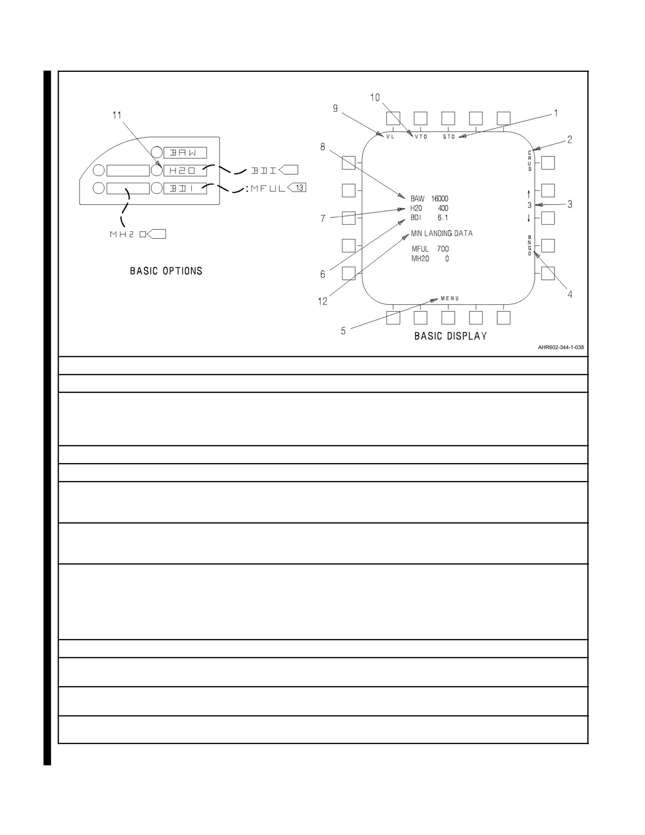
The V/STOL--REST basic display appears with the last entered values for the basic aircraft weight (BAW), water
weight (H2O) and basic drag index (BDI). Also the UFC and ODU are enabled for data entry. To ensure accuracy
thedisplayed values forBAW, H2O, and BDImust beverified and new values entered if required. The H2O quantity,
as indicated on the EDP, is displayed on the V/STOL--REST basic display in aircraft with H4.0 and cannot be altered.
2.20.1 VREST Displays
There are five VREST displays: vertical landing (VL), vertical takeoff (VTO), short takeoff (STO), cruise (CRUS),
and bingo (BNGO). To enable the desired display select the appropriate pushbutton VL, VTO, STO, CRUS or
BNGO. Selection is indicated by the box around the legend.
2.20.1.1 Vertical Takeoff and Landing Display
The vertical takeoff and vertical landing displays are identical in format. The displays show the maximum weight
of fuel and water (F+W) aboard the aircraft at which the vertical takeoff or vertical landing can be performed. This
data is computed for both WET (water injected in engine) and DRY operation. If the outside air temperature is below
--5 °C/23 °F the WET data is not displayed.
The data displayed at the bottom of the display; outside air temperature Celsius/Fahrenheit (OATC or OATF),
altimeter barometric pressure setting (ALTM), field elevation (FELV), and gross weight (GWT) is normally system
generated and used in calculating maximum F+W. If any of these parameters are not valid then that parameter is not
displayed. If the non--valid parameter is essential to calculations of maximum F+W, then the calculation is not
performed and no data is displayed for maximum F+W.
Some data affecting the calculations may be entered by the pilot using the options on the ODU. The following options
are available: GWT, OATC or OATF, FELV, and engine parameters (ENG). Selecting ENG enables the relative jet
pipetemperature(RJPT),jetpipetemperaturelimit(JPTL)andrelativehover(RHOV)options.Ifdatais pilotentered
(OATC or OATF, GWT, FELV) and asterisk (*) is displayed to the left of the applicable legend. Pilot entered data
overrides system generated data.
The maximum F+W is calculated as follows: first the hover weight is calculated. This is done by calculating the
maximum rpm limited by ambient temperature, then calculating the maximum rpm limited by jet pipe temperature
limiter settings. Since either of these parameters may limit the maximum rpm, the smaller of the two is used in the
equations to calculate the hover weight. The hover weight is then adjusted for either the takeoff or landing
calculations. For a vertical takeoff 97 percent of the hover weight is used. For a vertical landing approximately 95
percent of the hover weight is used. The adjusted hover weight is used along with the aircraft gross weight, fuel
weight, and water weight to calculate the maximum fuel plus water weight at which a vertical operation can be
executed.
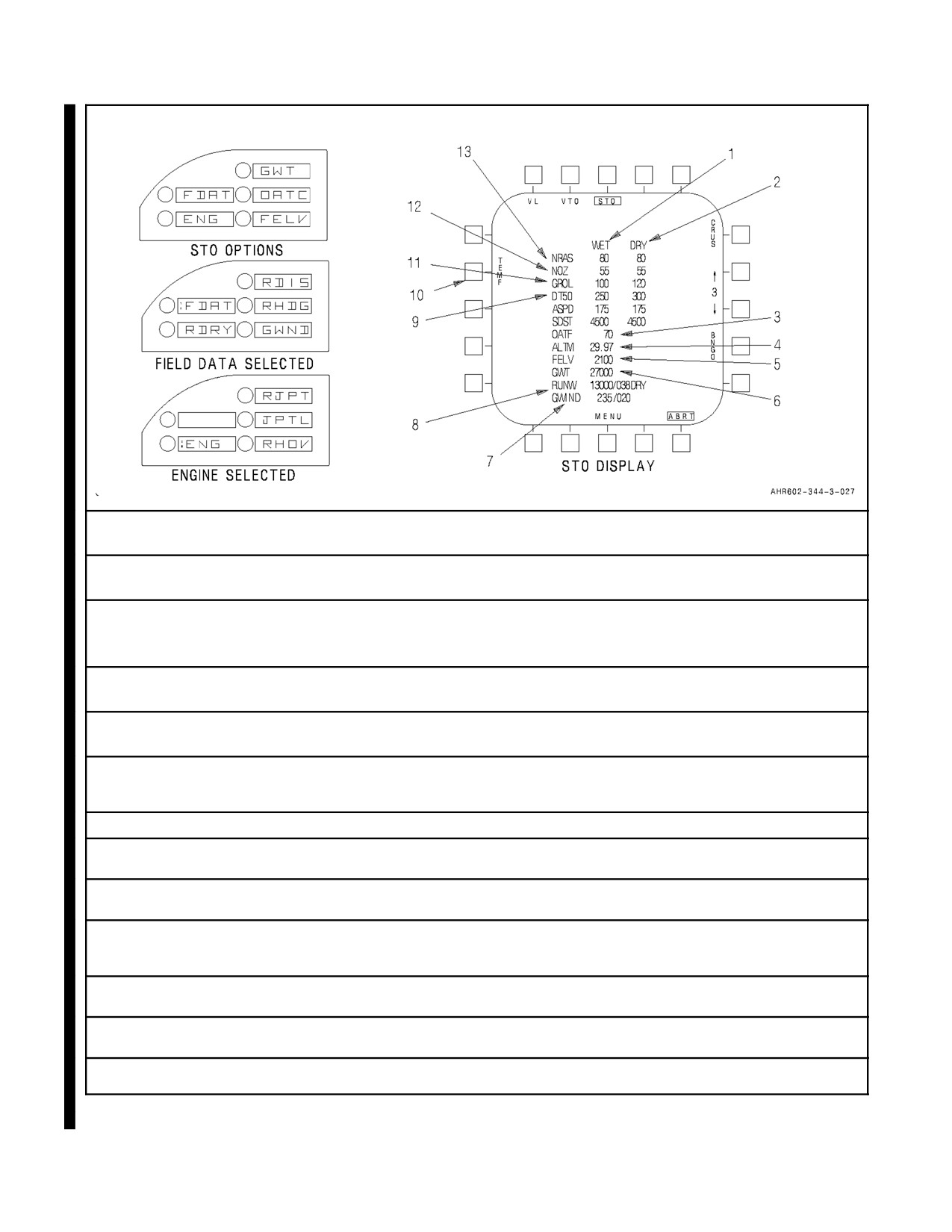
2.20.1.2 Short Takeoff Display
The short takeoff display shows the nozzle rotation airspeed (NRAS), nozzle setting in degrees (NOZ), minimum
ground roll distance (GROL), distance required to clear a 50 foot obstacle (DT50), abort speed (ASPD), and stopping
distance (SDST). Setting the nozzles to the displayed NOZ when NRAS is reached results in the displayed GROL,
DT50, ASPD, and SDST. ASPD and SDST are computed and displayed when the abort (ABRT) push button is
2-77
ORIGINAL
A1-AV8BB--NFM--000
selected on the VRST page. The ASPD and SDST fields display asterisks (* * *) when ABRT is not selected, when
relevant inputs change, and in any weight on wheels condition. The data is computed for both WET (water injected
in engine) and DRY operation having no effect on ASPD or SDST. If outside air temperature is below --5 °C/23 °F
the WET data is not displayed.
The value of OATC or OATF, FELV, and GWT shown at the bottom of the display is system generated but may be
overridden by the pilot. The value for ALTM is equal to the barometric pressure setting set on the standby pressure
altimeter. Runway data (RUNW) and ground wind (GWIND) are pilot entered inputs. If any of these parameters are
not valid then that parameter is not displayed. If the non--valid parameter is essential to the calculations of NRAS,
NOZ, GROL, and DT50 then the calculation is not performed and no data is displayed, with the exception of ASPD
and SDST fields. These two fields display solid asterisks if they become invalid, and during initial fire up.
Data affecting the calculations may be entered by the pilot using the options on the ODU. The following options are
available: GWT, OATC or OATF, FELV, field data (FDAT), ENG. Selecting the FDAT option enables runway
distance (RDIS), runway heading (RDHG), runway wet/dry (RWET/RDRY), and ground wind (GWND) options;
selecting the ENG option enables relative jet pipe temperature, jet pipe temperature limit, and relative hover options.
The RDRY selection toggles between RDRY and RWET, with the default being RDRY. RDIS allows entries from
1,000 to 13,000 feet, with the default being 1,000 feet. If system generated data is overridden by pilot entered data
(OATC or OATF, GWT, and FELV) an asterisk (*) is displayed to the left of the applicable legend.
Note
(ABRT USES 6,000) is displayed when field elevation is greater than 6,000
feet and (CALC 1,400) is displayed when runway condition is wet and
runway length is less than 1,400 feet.
The nozzle rotation airspeed, nozzle setting in degrees, ground roll distance, and the distance required to clear a 50
foot obstacle are calculated as follows: first the hover weight is calculated based on the limiting rpm; maximum rpm
limited by ambient temperature or maximum rpm limited by the jet pipe temperature limiter setting. Next, the gross
weight to hover weight ratio is calculated. If the ratio is less than 1.35 the nozzle rotation angle is set to 55°. If ratio
is greater than 1.35 the nozzle rotation angle is set to 50°. The airspeed for nozzle rotation is based on aircraft gross
weight and the gross weight to hover weight ratio. If the aircraft gross weight is greater than 27,000 pounds and
ambient temperature is greater than 35 °C/95 °F the nozzle rotation airspeed and ground wind are used to compute
the ground roll distance. The ground roll distance and outside air temperature are used to compute the distance to
clear a 50 foot obstacle. Refer to A1--AV8BB--NFM--400, see Short Takeoff Rotation Speed charts for additional
details.
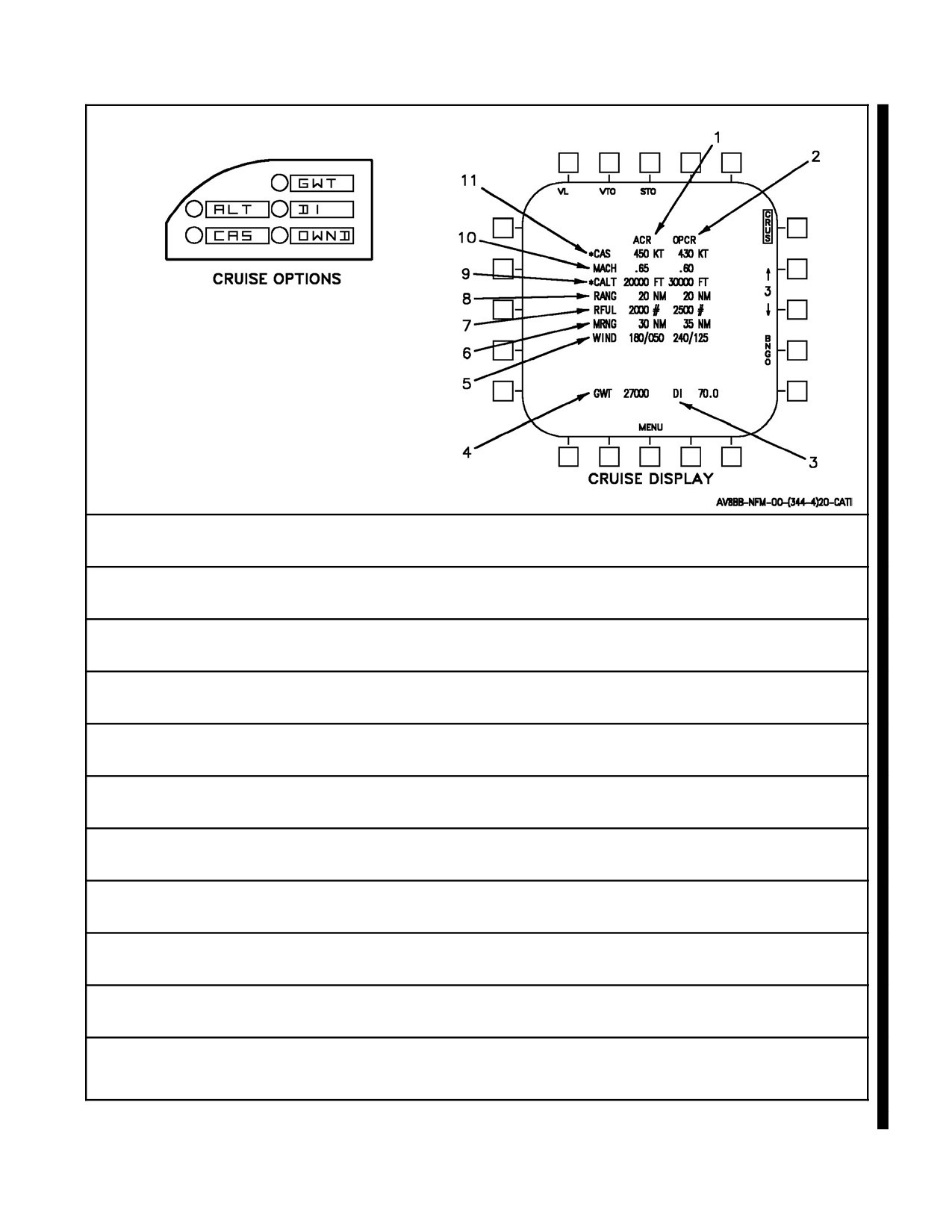
2.20.1.3 Cruise Display
The cruise display presents the best flight profile for altitude cruise (ACR) and optimum cruise (OPCR) performance.
The ACR column displays the profile necessary to obtain the maximum cruise performance at the existing altitude.
The OPCR column displays the flight profile at which maximum cruise performance can be obtained. The data in
the ACR column is system generated as is most data in the OPCR column. In the OPCR column the exceptions are:
system generated values for calibrated airspeed (CAS) and cruise altitude(CALT) can be overridden by pilot entries.
The WIND entry must be pilot entered.
The ODU options available for data entry are gross weight (GWT), drag index (DI), optimum cruise wind (OWND),
cruise altitude (ALT), and calibrated airspeed (CAS).
When the display is selected CALCULATIONS IN PROGRESS appears while the parameters are being generated.
This may take as long as 12 seconds. The aircraft gross weight, drag index, current altitude, ambient temperature,
wind direction and speed, and range to selected waypoint are computed for use in determining the parameters in the
ACR and OPCR columns.
Altitude cruise calculations are performed first. The system tests for and calculates the Mach number which results
in the best fuel efficiency at the current altitude. The average gross weight, total drag, dynamic pressure, and wind
effects during the cruise are some of the factors considered when calculating the Mach number. The Mach number
and equivalent calibrated airspeed are displayed in the ACR column. Fuel consumption is calculated by taking the
ORIGINAL
2-78
A1-AV8BB--NFM--000
cruise range and dividing it by the fuel efficiency. The remaining fuel, displayed in the ACR column, is the total fuel
minus the fuel consumed during the climb, cruise, and descent. The maximum range allows for an 800 pound fuel
reserve and is calculated by multiplying the available fuel by fuel efficiency.
Optimum cruise calculations are performed next. The system tests for and calculates the Mach number and altitude
that results in the best fuel efficiency. First the fuel and distance to climb to the current altitude is calculated. Next,
the optimum cruise altitude is calculated based on the weight and drag index of the aircraft. Altitudes between the
current altitude and the optimum altitude are examined at intervals to see which one provides the greatest fuel
efficiency. Next, fuel consumption calculations are done to determine how much fuel will remain when the waypoint
or markpoint is reached. After all altitudes have been tested the calculated values for the optimum altitude and Mach
numberaredisplayed. Theoptimum Mach number is also converted to theequivalent calibrated airspeed fordisplay.
The pilot can manually enter an altitude and/or airspeed for the optimum cruise calculations if threats or the weather
dictate. The ALT and CAS options are displayed on the ODU when CRUS is selected on the DDI. Any altitude less
thanorequaltotheoptimumcruisealtitudeoranyairspeedbelow600knotscanbeentered byselecting theapplicable
option, ALT or CAS, and keying the desired entry. Altitude entries greater than the optimum altitude and airspeed
entries 600 knots or greater are disallowed and denoted by the flashing entry on the scratch pad. Manual entries of
altitude or airspeed for optimum cruise calculations are denoted by an asterisk (*) preceding the CALT and/or CAS
legend.
2.20.1.4 Bingo Display
The bingo display presents the best flight profile for altitude bingo (ABNG) and optimum bingo (OBNG)
performance. The ABNG column displays the flight profile necessary to obtain maximum bingo performance at the
existing altitude. The data in the ABNG column is system generated as is most data in the OBNG column. In the
OBNG column the exceptions are: system generated values for CAS and CALT can be overridden by pilot entries.
The WIND entry must be pilot entered.
The ODU options available for data entry are gross weight, drag index, optimum cruise wind, cruise altitude, and
calibrated airspeed.
When the display is selected CALCULATIONS IN PROGRESS appears while the parameters are being generated.
This may take as long as 12 seconds. The aircraft gross weight, drag index, current altitude, ambient temperature,
wind direction and speed, and range to selected waypoint are computed for use in determining the parameters in the
ABNG and OBNG columns. Constant altitude computations are done first. A minimum drag index is set, a fuel
reserve (800 pounds) is subtracted from the total fuel on board and gross weight is adjusted based on fuel to be used.
Maximum range is computed based on total fuel and fuel flow. Constant altitude data is stored for display.
Optimum altitude computations are done next. The fuel required to climb from sea level to the existing altitude is
computed. The optimum altitude is computed based on total fuel. If the optimum altitude is greater than the existing
altitude, the amount of fuel and distance to climb to the optimum altitude is computed. The amount of fuel to be used
for cruise leg is the total fuel minus the climb fuel. The constant altitude bingo computations are done and climb range
is added to the cruise range to get maximum range. The amount of fuel and distance to climb from sea level to the
existing altitude is computed. Then the amount of fuel and distance to climb from sea level to the optimum altitude
is computed. The amount of fuel and distance to climb to the optimum altitude is the difference between the two
values.
The pilot can manually enter an altitude and/or airspeed for the optimum bingo calculations if threats or weather
dictate. The manual entries are accomplished in the same manner as previously described for the optimum cruise
calculations.
2.20.2 Engine Data Entry
To receive the proper ODU displays for entering engine data, press the VRST pushbutton on the DDI basic menu
display. The DDI shows the basic V/STOL--REST display (Figure 2-22). The ODU displays BAW, H2O (OMNI 7.1
and C1+ only), and BDI. Pressing the VL, VTO, or STO pushbutton on the DDI display causes OATC or OATF,
FELV, GWT, and ENG to appear on the ODU option display windows. Corresponding displays appear on the DDI.
To enter engine data select the ENG option. A colon appears next to the ENG legend indicating selection. The relative
jet pipe temperature, jet pipe temperature limit, and relative hover options are displayed. Selecting anyone of these
options enables the UFC scratch pad and keyboard for data entry. A colon appears to the left of the selected option.
2-79
ORIGINAL
A1-AV8BB--NFM--000
12
12
1.
Pressing this pushbutton selects short takeoff display and causes STO to be boxed, indicating selection.
2.
Pressing this pushbutton selects cruise display and causes CRUS to be boxed, indicating selection.
3.
Number (3) indicates selected waypoint. Waypoint can be changed by pressing the increment (↑) or
decrement (↑) pushbutton. Changing waypoint does not change waypoint selection on EHSI/EHSD display.
With H4.0, pressing the increment or decrement pushbutton for more than 0.8 seconds enables a quick
access session allowing the pilot to select between all 60 waypoints, 10 markpoints, and 5 targetpoints.
4.
Pressing this pushbutton (BNGO) selects bingo display and causes BINGO to be boxed, indicating selection.
5.
Pressing this pushbutton (MENU) selects menu display.
6.
Basic drag index (BDI) is entered by the pilot for use in drag index computations. Drag index values from 0 to
30 may be entered. The displayed drag index is for aircraft in a clean configuration and does not include
compensation for external stores.
7.
With OMNI 7.1 and C1+, water weight (H2O) is entered by the pilot for use in gross weight computations. The
displayed water weight is the last entered value. With H4.0, the displayed water weight is the same as the
EDP water weight.
8.
Basic aircraft weight (BAW). The operating weight (OWT) is entered here for use in gross weight
computations. The maxi mum allowable entry is 20,000 pounds. The OWT is the BASIC WEIGHT plus those
items which remain constant for the mission. These items include the pilot (180 lbs), ALE 39/47 (111 lbs),
strakes, gun, pylons, probe, etc. This weight does not include expendable stores, empty ITERS, TPOD, water
or fuel. The weight entered here should match the DSU Aircraft Weight at the bottom of section 3 on the
AV--8B UPC generated Form F.
9.
Pressing this pushbutton (VL) selects vertical landing display and causes VL to be boxed, indicating selection.
10.
Pressing this pushbutton (VTO) selects vertical takeoff display and causes VTO to be boxed, indicating
selection.
11.
With H4.0, ODU window 2 has changed to BDI. ODU window 3 and 5 are blank for Radar and Night Attack
aircraft.
12.
Minimum Fuel (MFUL) and Minimum water (MH2O) can be entered by the pilot in TAV--8B aircraft with H4.0.
This will allow the system to display VL performance that is corrected for RJPT shift.
Figure 2-22. VSTOL -- REST Displays (Sheet 1 of 5)
ORIGINAL
2-80
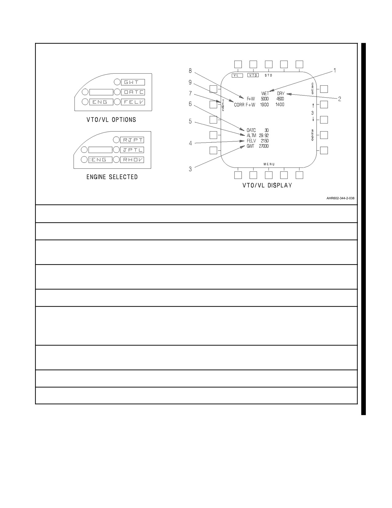
A1-AV8BB--NFM--000
1.
Wet is displayed above left column. The numerics listed below WET are the values to be used in a water
injected takeoff or landing. WET data are not displayed if outside air temperature is below --5 °C.
2.
Dry is displayed above right column. The numerics listed below DRY are values to be used in a DRY (not
water injected) takeoff or landing.
3.
Aircraft gross weight (GWT) is the total weight of the aircraft including fuel, water, stores including hung stores,
and rounds remaining including spent casings. The GWT is used to compute F+W. If displayed GWT is pilot
entered, an asterisk (*) is displayed to the left of GWT.
4.
Field elevation (FELV) is used to compute the maximum allowable F+W weight. The displayed FELV is either
computed or pilot entered. An asterisk (*) is displayed to the left of FELV if pilot entered field elevation is being
used.
5.
Altimeter barometric pressure setting (ALTM) is used to compute F+W. The displayed ALTM is equal to the
barometric pressure setting that is set on the standby pressure altimeter.
6.
Outside air temperature °C (OATC) or °F (OATF) is used to compute F+W. The displayed OAT is either pilot
entered or is set equal to the last computed ground temperature. Once weight is off wheels, OAT is no longer
automatically updated; however, the pilot may manually change the temperature if desired, at which time an
asterisk (*) is displayed to the left side of OATC or OATF as applicable. The last recorded temperature is
stored.
7.
This pushbutton allows the outside air temperature to be entered and displayed in units Fahrenheit or Celsius.
The pushbutton scrolls between TEMF and TEMC. The outside air temperature on the VL, VTO, STO and
PHOV display is calculated and displayed as OATF or OATC.
8.
Fuel and water weight (F+W) is computed for WET or DRY takeoff or landing. The displayed value is the
maximum weight of fuel and water aboard the aircraft at which the vertical takeoff or landing can be done.
9.
The corrected F+W display line indicates the vertical landing values (corrected for RJPT shift) based on the
minimum landing fuel and water inputs for TAV--8B aircraft with H4.0.
Figure 2-22. VSTOL -- REST Displays (Sheet 2)
2-81
ORIGINAL
A1-AV8BB--NFM--000
1.
WET is displayed above left column. The data in the WET column are the variables to be used if a water injected short takeoff is to be
done. The data is always computed when STO is selected, but will not be displayed if outside air temperature is below --5 °C.
2.
DRY is displayed above right column. The data in the DRY column are the variables to be used if a dry (not water injected) takeoff is to
be done.
3.
Outside air temperature °C (OATC) or °F (OATF) is used in performance computations to determine the variables required for a STO.
The displayed OAT is either pilot entered or is set equal to the last computed ground temperature. Once weight is off wheels, OAT is
no longer automatically updated; however, the pilot may manually change the temperature if desired, at which time an asterisk (*) is
displayed to the left side of OATC or OATF as applicable. The last recorded temperature is stored.
4.
Altimeter barometric pressure setting (ALTM) is used in performance computations to determine the variables for the STO. The
displayed ALTM value is equal to the barometric pressure setting that is set on the standby pressure altimeter.
5.
Field elevation (FELV) is used in performance computations to determine the variables required for STO. The displayed FELV is either
computed or pilot entered. If pilot entered an asterisk (*) is displayed to the left side of FELV.
6.
Aircraft gross weight (GWT) is the total weight of the aircraft including fuel, water, stores including hung stores, and rounds remaining
including spent casings. The GWT is used in performance computations to determine the variables required for STO. The displayed
GWT is either computed or pilot entered. If pilot entered, an asterisk (*) is displayed to the left of GWT.
7.
Ground wind (GWIND) is displayed indicating wind direction and magnitude. It is pilot entered.
8.
Runway (RUNW) displays runway distance (RDIS), runway heading (RHDG), and runway condition (RDRY/RWET), which are all pilot
entered.
9.
Distance to 50 feet (DT50) is displayed with entries in WET and DRY columns. Number indicates linear distance in feet required for a
50 foot obstacle clearance.
10.
This pushbutton allows the outside air temperature to be entered and displayed in units Fahrenheit or Celsius. The pushbutton scrolls
between TEMF and TEMC. The outside air temperature on the VL, VTO, STO and PHOV display is calculated and displayed as OATC
or OATF.
11.
Ground roll (GROL) is displayed with entries in the WET and DRY columns. Number indicates minimum ground roll distance required
for short takeoff.
12.
Nozzle setting in degrees (NOZ) is displayed with entries in WET and DRY columns. The nozzle setting for a STO is 50° or 55°
depending upon the hover weight ratio. NOZ displays the setting to which the nozzles should be rotated when NRAS is reached.
13.
Nozzle rotation airspeed (NRAS) is displayed with entries in the WET and DRY columns. The NRAS is the airspeed at which nozzles
are rotated to do a STO. Setting the nozzles to displayed NOZ when NRAS is reached results in the displayed GROL and DT50.
Figure 2-22. VSTOL -- REST Displays (Sheet 3)
ORIGINAL
2-82
A1-AV8BB--NFM--000
1.
Altitude cruise (ACR) is displayed above left column. Numbers in this column are computed to indicate to the pilot the flight data
required to obtain maximum cruise performance at existing altitude. An asterisk (*) next to the ACR legend indicates existing aircraft
altitude is greater than optimum altitude. When this occurs data in the ACR column is extrapolated from the data in the OPCR column.
2.
Optimum cruise (OPCR) is displayed above right column. Numbers in this column are computed to indicate to the pilot the optimum
altitude at which the maximum cruise performance can be obtained.
3.
Drag index (DI) is displayed to indicate total drag of aircraft and stores. The drag index is used in cruise computations. If an asterisk (*)
is displayed to the left of DI, a pilot entered drag index is being used in computations.
4.
Gross weight (GWT) is displayed to indicate total weight of aircraft, including fuel, water, stores including hung stores, and rounds
remaining including spent casings. The gross weight is used in cruise computations. An asterisk (*) to the left of GWT indicates that a
pilot entered value is being used in computations.
5.
Wind is displayed in direction and magnitude in both the altitude cruise and optimum cruise columns. Displayed ACR wind is computed
from aircraft sensors. OPCR wind is a pilot entered value.
6.
Maximum range (MRNG) is displayed in altitude cruise and optimum cruise columns. MRNG indicates maximum range that can be
reached if the altitude, airspeed, and Mach of respective columns is followed. The MRNG computations allow a 800 pound fuel
reserve.
7.
Remaining fuel (RFUL) legend is displayed with entries in ACR and OPCR columns. Number indicates remaining fuel in pounds after
arriving at selected waypoint if ACR or OPCR profile is followed.
8.
Range (RANG) legend is displayed with entries in ACR and OPCR columns. Number indicates range in nautical miles to the selected
waypoint. If range is more than 10,000 nautical miles, cruise data is blanked.
9.
Cruise altitude (CALT) legend is displayed with entries in ACR and OPCR columns. Number in ACR column indicates existing aircraft
altitude. Number in OPCR column indicates best altitude for use with other OPCR variables to increase maximum cruising range.
Aircraft can have a pilot entered altitude in the OPCR column, denoted by an asterisk (*) next to CALT legend.
10.
Mach legend is displayed with entries in ACR and OPCR columns. Number in ACR column indicates the best Mach to increase
aircraft range at existing altitude. Number in OPCR column indicates best Mach for use with other OPCR variables to increase
maximum cruising range.
11.
Calibrated airspeed (CAS) legend is displayed with entries in ACR and OPCR columns. Number in ACR column indicates the best
airspeed to increase aircraft range at existing altitude. Number in OPCR column indicates best airspeed for use with other OPCR
variables to increase maximum cruising range. Aircraft can have a pilot entered CAS in the OPCR column, denoted by an asterisk (*)
next to CAS legend.
Figure 2-22. VSTOL -- REST Displays (Sheet 4)
2-83
ORIGINAL
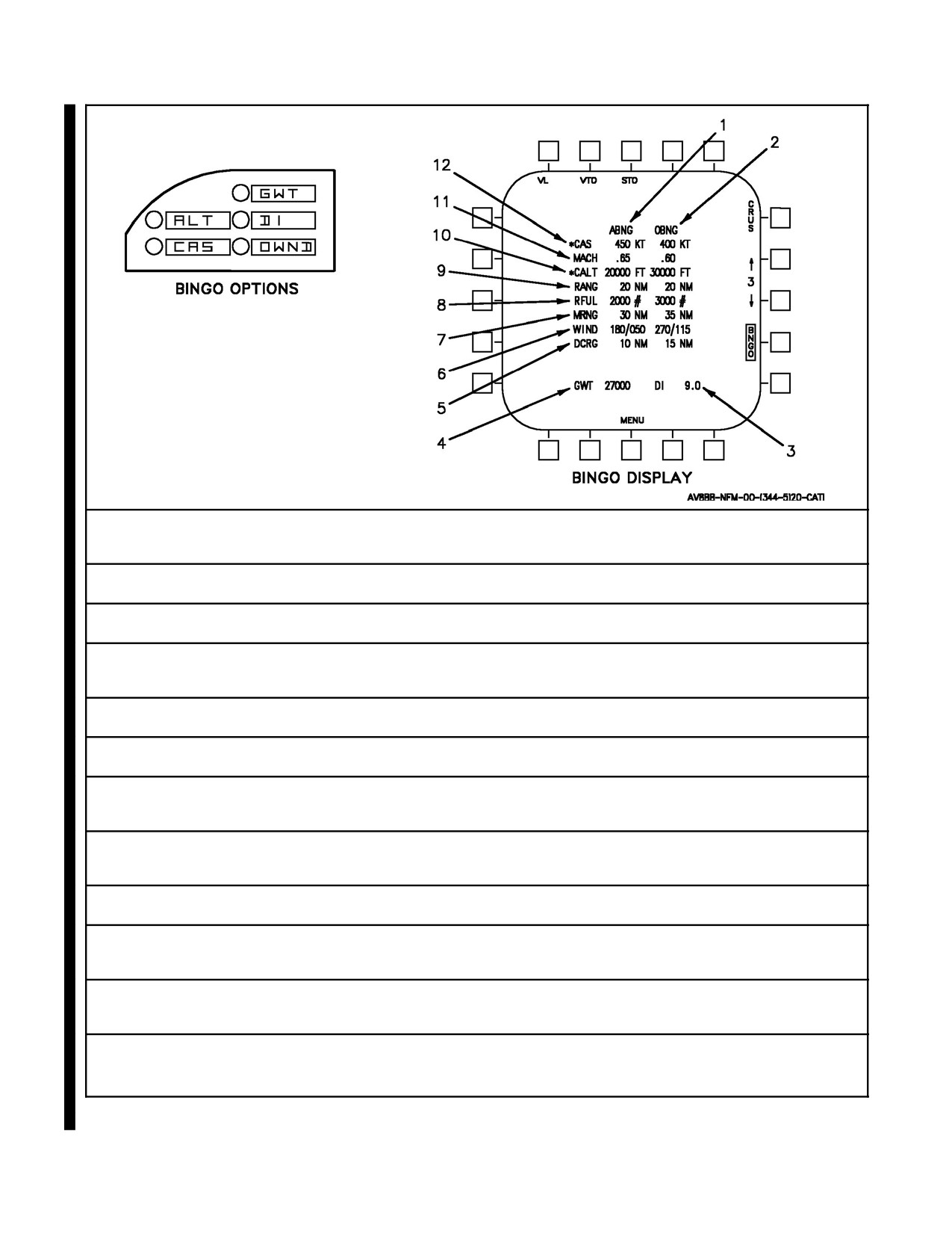
A1-AV8BB--NFM--000
1.
Altitude bingo (ABNG) legend is displayed above left column. Numbers in this column indicate to the pilot flight data required to obtain
maximum bingo performance at existing aircraft altitude. An asterisk (*) next to the ABNG legend indicates existing aircraft altitude is
greater then optimum altitude. When this occurs data in the ABNG column is extrapolated from the data in the OBNG column.
2.
Optimum bingo (OBNG) legend is displayed above right column. Numbers in this column indicate to the pilot the optimum altitude at
which the greatest bingo performance can be obtained.
3.
Drag index (DI) is displayed to indicate total drag of aircraft. This drag index is used in computations and is set to a clean
configuration for bingo flight. Aircraft can have pilot entered drag index.
4.
Gross weight (GWT) is displayed to indicate bingo weight of aircraft including fuel, water, and spent casings but not including stores
including hung stores, expendables, or rounds remaining. An asterisk (*) to the left of GWT indicates a pilot entered value is being
used in computations.
5.
Descent range (DCRG) is displayed to indicate the range to the waypoint at which descent should begin for altitude bingo or optimum
bingo flight.
6.
Wind is displayed in the altitude bingo and optimum bingo columns. Displayed ABNG wind is computed form aircraft sensors. OBNG
wind is a pilot entered value.
7.
Maximum range (MRNG) indicates maximum aircraft range in nautical miles in the direction of the selected waypoint, including cruise
at the displayed altitude followed by an idle descent to sea level. Fuel remaining after descent is 800 pounds.
8.
Remaining fuel (RFUL) legend is displayed with entries in ABNG and OBNG columns. Number indicates fuel remaining in pounds after
arriving at selected waypoint, if ABNG or OBNG profile is followed.
9.
Range (RANG) legend is displayed with entries in ABNG or OBNG columns. Number indicates range in nautical miles to selected
waypoint. If range is more than 10,000 miles, bingo data is blanked.
10.
Cruise altitude (CALT) legend is displayed with entries in ABNG and OBNG columns. Number in ABNG column indicates existing
aircraft altitude. Number in OBNG column indicates best altitude for maximum cruising range. Aircraft can have pilot entered altitude in
OBNG column, denoted by an asterisk (*) to the left of CALT.
11.
Mach legend is displayed with entries in ABNG and OBNG columns. Number in ABNG column indicates the best Mach to increase
aircraft range at existing altitude. Number in OBNG column indicates best aircraft Mach for use with other OBNG variables to increase
maximum range.
12.
Calibrated airspeed (CAS) legend is displayed with entries in ABNG and OBNG columns. Number in ABNG column indicates the best
airspeed in knots to increase aircraft range at existing altitude. Number in OBNG column indicates best airspeed for use with other
OBNG variables to increase maximum range. Aircraft can have pilot entered CAS in OBNG column, denoted by an asterisk (*) next to
the left of CAS.
Figure 2-22. VSTOL -- REST Displays (Sheet 5)
ORIGINAL
2-84
A1-AV8BB--NFM--000
2.20.3 VREST Calculation Considerations
2.20.3.1 Lateral Asymmetries
The VREST computer does not account for performance degradations induced by lateral asymmetries. Therefore,
for takeoffs with lateral asymmetries above 32,000 inch--pounds, increase VREST calculated STO NRAS by 10
KCAS. For takeoffs with lateral asymmetries above 80,000 inch--pounds, increase VREST calculated STO NRAS
by 15 KCAS.
2.20.3.2 Gross Weight and Air Temperature
The VREST computer does account for aircraft gross weight in STO NRAS calculation, whereas the charts depicted
in A1--AV8BB--NFM--400 do not. Therefore, there is no requirement to add 5 KCAS to VREST calculated STO
NRAS for takeoffs at gross weights greater than 27,000 pounds when ambient air temperature exceeds 35 °C.
2.21
AIR DATA COMPUTER
The air data computer (see Figure 2-23) is a solid state digital computer which receives inputs from the magnetic
azimuth detector, standby altitude Kohlsman setting, TOT probe, AOA transmitter, mission computer, and
pitot/static pressure. Accurate air data and magnetic heading are computed. The air data provided to the mission
computer accounts for air data compensation, position error calibration, and converts indicated airspeed to calibrated
airspeed. Computed data is supplied to the mission computer system, altitude reporting function of the IFF,
multipurpose display system, SAAHS, aileron high speed stops, flap controller, LIDS, Q--feel, stall warning, landing
gear up warning, APU and DECS.
2.21.1 Total Temperature Probe
The total temperature probe is on the upperleft sideof thevertical stabilizer. Operation ofthe probeheater is covered
under Probe Heat Switch in Instruments, this section. The air data computer uses total temperature to calculate
ambient temperature.
2.21.2 ADC BIT Check
To perform an initiated ADC BIT check, press the BIT pushbutton on the DDI menu display to initiate a BIT display.
Press the ADC pushbutton and the word TEST appears next to ADC. After several seconds the word TEST
disappears. If a failure code then appears next to ADC the system has failed the BIT check. If the space next to ADC
remains blank the system has checked good.
2.22
ENTRANCE/EGRESS SYSTEMS (AV--8B)
2.22.1 Canopy System/Boarding Steps
Thecockpit areais enclosed by asliding typecanopy which consists ofacast acrylictransparency mountedin ametal
frame. The canopy is mounted on rails which slope upward toward the rear of the aircraft. The canopy is
counterbalanced to the open position by a spring and pulley system. Except for the aid provided by the
counterbalance, the canopy is opened and closed manually. A canopy seal, routed around the canopy frame, is
automatically inflated by a solenoid operated pneumatic valve whenever the WOW sensor indicates weight is off
wheels.
Note
The windscreen birdstrike protection capability is analytically estimated at
350 knots for a one pound bird.
Normal entrance/egress is gained by four boarding steps on the right forward fuselage below the canopy. One step
is mechanically linked to the canopy, and moves down when the canopy is opened and up when thecanopy is closed.
The other steps are in the moldline of the fuselage and provide steps/handholds for entrance/egress.
2-85
ORIGINAL
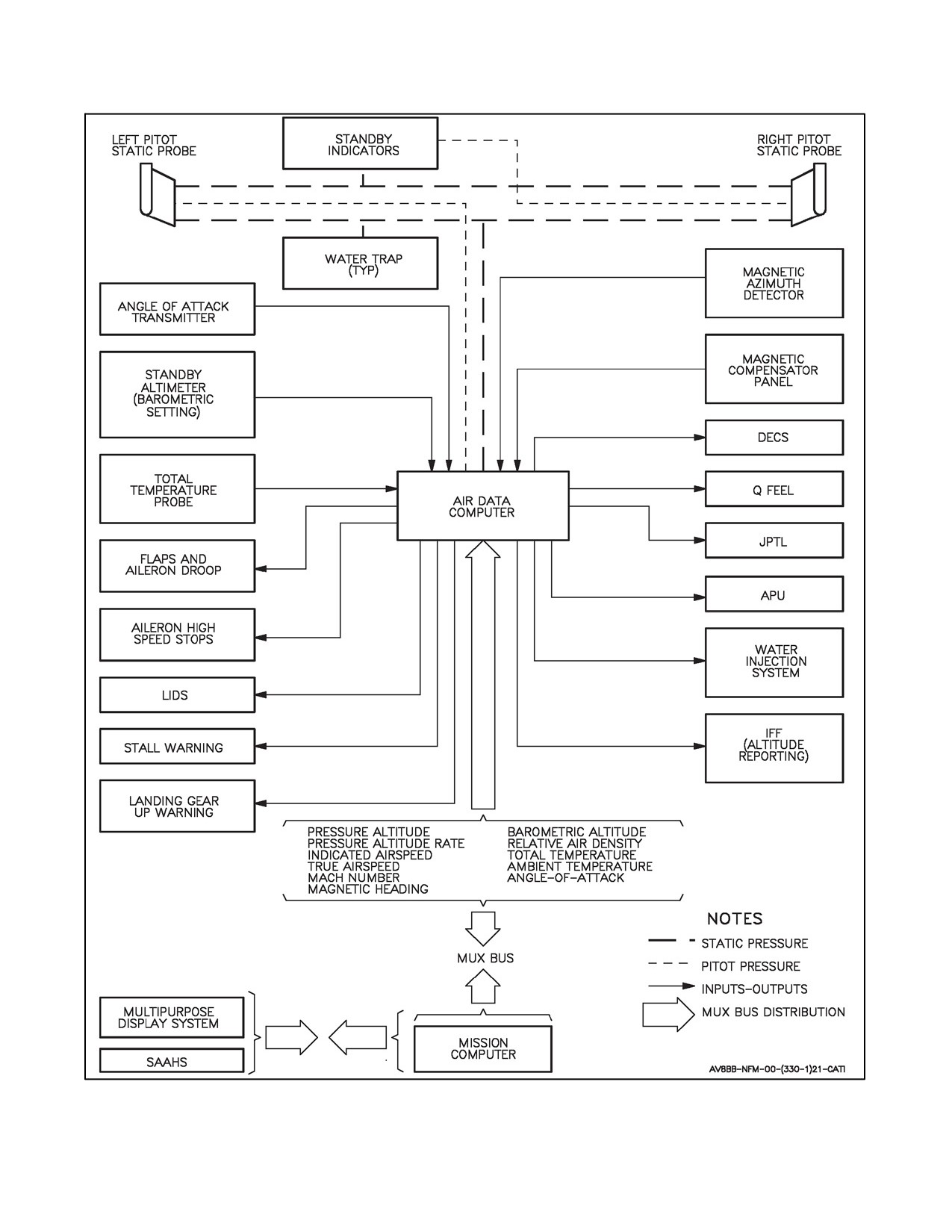
A1-AV8BB--NFM--000
Figure 2-23. Air Data Computer Interface
ORIGINAL
2-86
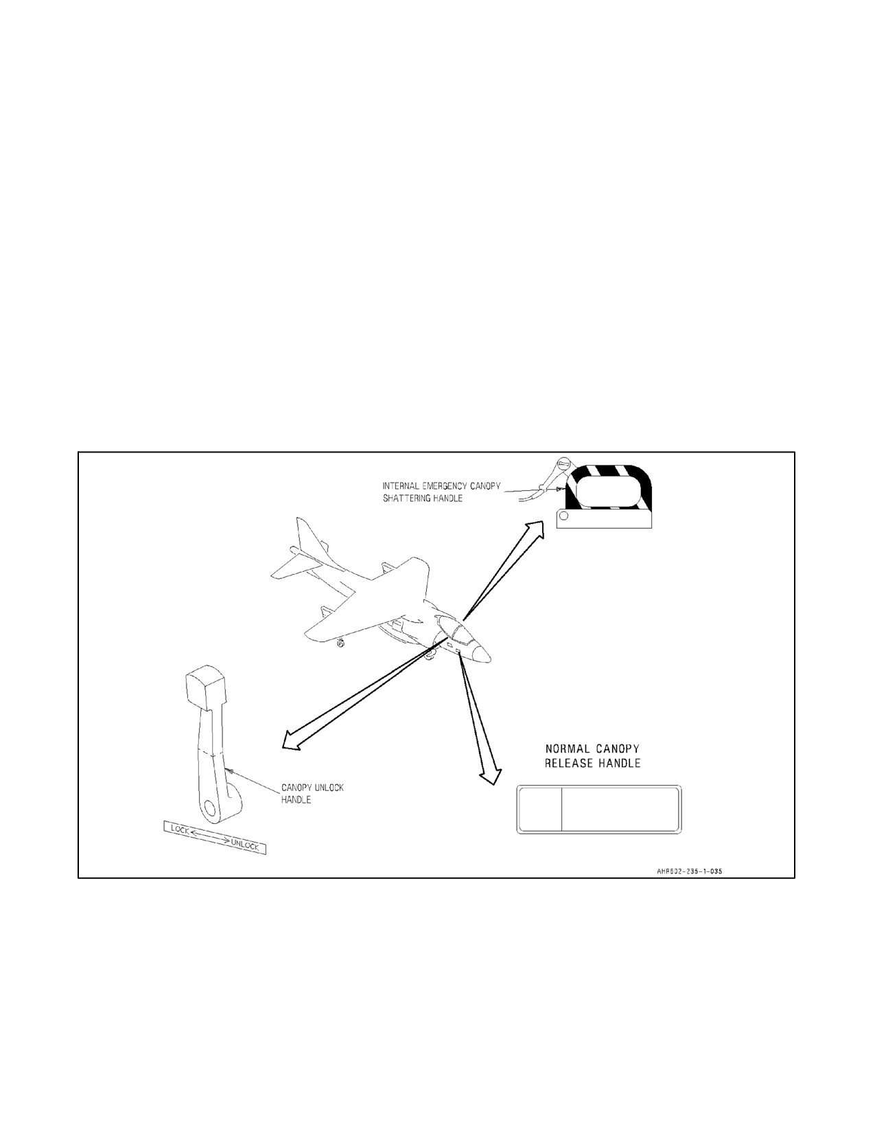
A1-AV8BB--NFM--000
2.22.2 Normal Canopy System
The canopy operating mechanism is mechanically linked to a boarding step on the right forward fuselage so that as
thecanopy opens thestep extends and as thecanopy closes thestep retracts. When moved to thefully closedposition,
the canopy is automatically locked by two latches at the intersection of the lower leading edge of the canopy bow
and the windshield frame. The controls for normal operation are the external canopy release handle, the internal
canopy unlock handle and the canopy bow handles. The external canopy release handle and internal canopy unlock
handle unlock the canopy and the canopy bow handles are used as grips to open and close the canopy. Close the canopy
using both bow handles to ensure both canopy latches are properly engaged. Once unlocked externally, the canopy
can be opened by applying downward force to the boarding step. Avoid use of the boarding step to close the canopy
due to probability of disengaging the canopy/boarding step interlock described in paragraph
2.22.2.5,
Canopy/Boarding Step Mechanical Link.
2.22.2.1 External Normal Canopy Release Handle
The external normal canopy release handle (Figure 2-24) is on the right side of the fuselage below the windshield.
The handle is labeled NORMAL CANOPY RELEASE HANDLE. Operating a push--type latch causes the handle
to pop out from a slot in the fuselage, and then pulling out and forward on the handle releases the two canopy locks.
After the canopy is unlocked, the counterbalance system causes the canopy to slide back while partially extending
the boarding step. Downward pressure on the step will fully open the canopy.
Figure 2-24. Canopy Controls (AV--8B)
2-87
ORIGINAL
A1-AV8BB--NFM--000
2.22.2.2 Boarding Steps
In addition to the boarding step which extends when the canopy is opened externally, there are three boarding steps
on theright sideof thefuselage below the canopy. These steps, which arestowed flush with moldlineof thefuselage,
are easily located by three vertical lines extending down from the canopy to the steps. To use the steps as
steps/handholds while entering or egressing the cockpit, the steps are unlocked by pushing PUSH buttons on the top
part of the two upper stowed steps. The lower stowed step is interconnected with the upper right step and operation
is controlled by the upper step. Unlocking the steps causes the steps to spring approximately 15° outboard and down
to form a step/handhold. The steps must be stowed before flight. To stow, the steps are rotated upward and inboard
by hand or foot. The steps lock in the stowed position when they become flush with the moldline of the aircraft.
On AV--8B prior to 162077, there are only two boarding steps in the moldline of the fuselage.
On AV--8B 162077 and up, a third step is added approximately 28 inches forward of the top step, and above and
slightlytotherightofthelowerstep.Thestepoperatesthesameasthestepsintheearlieraircraftandisinterconnected
to the lower step so that the latch of this step must be used to unlock both steps.
CAUTION
Egressing the cockpit without using the steps may cause injury. Pilots
should be familiar with the location of the step release without requiring a
visual so that the steps may be quickly unlocked and used in case of an
emergency egress.
2.22.2.3 Canopy Internal Unlock Handle
The canopy internal unlock handle (Figure 2-24) is on the right side of the cockpit just forward of the lower part of
the windshield arch. Pulling aft on the handle releases the canopy locks to allow the canopy to be moved manually.
The handle is spring--loaded to the locked, or forward, position and there is no requirement to manipulate the handle
when locking the canopy.
2.22.2.4 Canopy Bow Handles
Two canopy handles are on the inside of the canopy bow on either side of the cockpit. After the canopy is unlocked,
the handles afford a means of opening or closing the canopy from within the cockpit.
2.22.2.5 Canopy/Boarding Step Mechanical Link
The mechanical link between the canopy and the drop down boarding step includes a disengagable interlock. Should
theboarding step bind orjam forany reason, such as during acrash landing wheretheground clearanceisinsufficient
for the step to fully drop, the interlock can be separated from the step by applying a sudden aft force to both canopy
handles. The interlock can be recoupled by holding the footsteps in the up position while moving the canopy forward
until resistance is felt, then applying a sudden forward force to both canopy bow handles.
2.22.2.5.1 Canopy Latch Viewports
Canopy latch viewports (Figure 2-25) are located on the right and left sides just forward of the lower edge of the
canopy. These viewports allow a visual check of the canopy latches to ensure that they are properly closed. If the
latches are up (not properly closed), orange alignment lines will not be aligned.
2.22.2.5.2 Canopy Caution Light
A CANOPY caution light on the caution/advisory light panel comes on when the canopy is not closed and locked.
The light operates in conjunction with the MASTER CAUTION light.
ORIGINAL
2-88
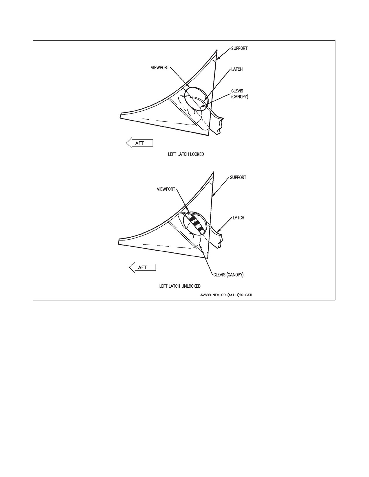
A1-AV8BB--NFM--000
Figure 2-25. Canopy Latch Viewport
2.22.2.6 Emergency Canopy Shattering System
Emergency operation of the canopy consists of detonating a small explosive charge of mild detonating cord (MDC)
which serves to break away or shatter the cast acrylic transparency. After the transparency is removed, the pilot can
depart through the canopy frame during ground egress. The MDC is a small diameter explosive cord attached around
the edge of the transparency near the canopy frame, and also attached in an overhead pattern on the top inside of the
canopy. The explosive is fired by one of the three emergency controls. The emergency canopy control is the internal
emergency canopy shattering handle inside the cockpit (Figure 2-24).
2.22.2.6.1 Internal Canopy Shattering Handle
Theinternalcanopyshatteringhandle(Figure2-24)isretainedbyaspring--loadeddetentinayellowand blackstriped
housing at the left forward corner of the canopy frame. The handle, also striped yellow and black, is attached to a
cable which is looped inside a cover to give approximately 5 inches of slack, before connecting to a mechanically
actuated initiator. After the cable slack is taken up and the handle is pulled, the MDC fires to remove the canopy
transparency. The purpose of the cable slack is to provide clearance for the pilot’s hand when the MDC fires.
2-89
ORIGINAL
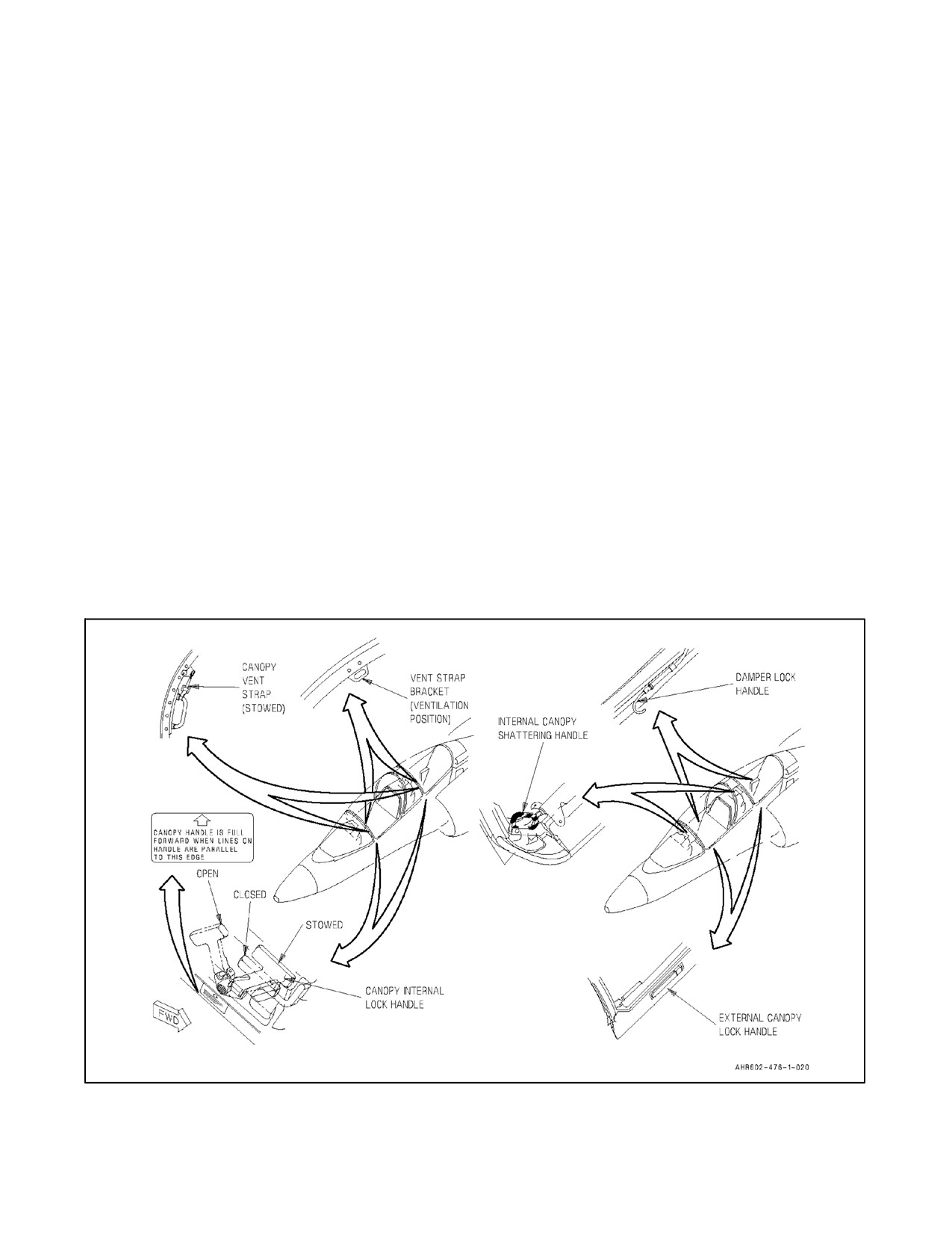
A1-AV8BB--NFM--000
2.23
CANOPY SYSTEM (TAV--8B)
Each cockpit (Figure 2-26) has a sideways opening, manually operated acrylic canopy, hinged on the right side. Each
canopy has a counterbalance torsion bar and a damper strut to assist in opening and closing. The damper strut has
a lock mechanism which locks the canopy when it reaches the full open position. Entry to each cockpit is normally
gained from the left side of the aircraft by means of a boarding ladder. There are no boarding steps or handholds
integral to the aircraft. Each canopy is locked independently by threeinterconnected latches which engageon theleft
side of the cockpit. The locks can be operated by interconnected external and internal controls. The external normal
controls are the external canopy lock handles. The internal normal controls are the canopy internal lock handles. A
CANOPY caution light, on the caution lights panel in both cockpits, provides indication that either or both canopies
are unlocked. Each cockpit has an inflatable canopy seal which operates on air from the anti--g system. The two
cockpit seals are interconnected and are inflated through an inflation control circuit when both canopies are closed
and locked with the engine running. The canopy seal circuit is controlled by operation of weight--on--wheels switches.
A clear polycarbonate blast shield is installed between the two cockpits. The shield serves to protect the rear seat
occupant from wind blast in situations where the front canopy is removed during flight. After AFC--373, a canopy
mounted shielded mild detonating cord (SMDC) actuated thruster is located on the forward canopy aft arch at the
aircraft centerline. The thruster fires a pin into the support located on the aircraft structure during ejection, securing
the aft canopy arch to the aircraft. This prevents the canopy arch from deflecting forward during ejection and
damaging the drogue chute bridle on the main parachute container. Damage to the bridle could result in drogue failure
with subsequent main chute damage and/or injury from high speed parachute deployment.
2.23.1 External Canopy Lock Handles
Each canopy can be unlocked by operation of the external canopy lock handle (Figure 2-26) on the left canopy frame.
The external handle is first extended by pressing the handle lock button. Once extended, rotate the external handle
clockwise till the open detent is engaged. The canopy internal lock handle rotates with the external handle. The
canopy is now unlocked and can be opened as far as possible, about 87°, to engage the damper lock. Before entering
the cockpit the external canopy lock handle should be stowed by pressing it flush with the mold line.
Figure 2-26. Canopy Controls (TAV--8B)
ORIGINAL
2-90
A1-AV8BB--NFM--000
2.23.2 Damper Lock Handles
Once in the cockpit, the canopy can be unlocked from the fully opened position by pulling forward on the damper
lock handle above the right canopy sill (Figure 2-26). The canopy can then be closed. If the canopy will not move,
the damper lock handle is not fully disengaged. The application of excess force on the canopy with the damper lock
handle engaged creates undue stress on the canopy acrylic and can lead to acrylic cracking and failure.
2.23.3 Canopy Internal Lock Handles
The canopy internal lock handle (Figure 2-26) is used to lock or unlock the canopy from inside the cockpit. Once
the canopy is closed it is locked by rotating thehandle forward till theclosed detent is engaged. The top of thehandle
is hinged and spring--loaded outboard so that it can be stowed behind a guard as it reaches the forward position. This
is to prevent inadvertent unlocking of the canopy. An indicator is provided with lines that are parallel to the canopy
sill when the handle is full forward. To unlock the canopy, pull the handle top inboard away from the guard, and then
rotate the handle back to engage the open detent. After the canopy is unlocked, normal cockpit egress is continued
by fully opening the canopy to engage the damper lock and extending the external canopy lock handle by pressing
the handle lock button. When opening the canopy care must be taken to slowly move the canopy to the full open
position until the damper lock engages. The canopy should not be allowed to freefall to the full open position,
additionally, the canopy should not be left open in windy conditions to prevent undue stress on the canopy acrylic.
Disengage the damper lock by pulling forward on the damper lock handle and close the canopy. Lock the canopy by
rotating the external canopy lock handle counterclockwise until the closed detent is engaged, and then stow the
external handle by pressing it flush with the mold line.
2.23.4 Canopy Caution Lights
A CANOPY caution light on the caution lights panel in both cockpits comes on when either or both canopies are
unlocked with power on the aircraft. The light circuits contain two micro switches which are actuated by the aft
canopy latch in the forward cockpit and the center canopy latch in the rear cockpit.
2.23.4.1 Pilot Assist Handles
Two pilot assist handles are provided in each cockpit. They are on the windshield arch in the front cockpit and the
forward canopy arch in the rear cockpit.
2.23.4.2 Canopy Vent Straps
On TAV--8B a canopy vent strap is provided on the assist handle in each cockpit. In utilization, the vent strap is
unhooked from the stowed position bracket (Figure 2-26) next to the assist handle. The canopy is opened
approximately 30° and the strap is hooked to a similar bracket on the canopy frame. The canopy is now secured in
the ventilation position. As the canopy is opened, the vent strap stops the canopy opening at the ventilation position.
The vent strap should be hooked back to the stowed position bracket when not in use.
2.24
EJECTION SEAT (AV--8B)
Each aircraft is equipped with an SJU--4/A ejection seat (Figure 2-27) which utilizes catapult cartridges and rocket
thrust to propel it from the aircraft. The SJU--4/A provides escape capability during takeoff and landing emergencies
at zero speeds, zero altitude, and throughout the remainder of the flight envelope of the aircraft, except for very
unusual flight conditions. The SJU--4/A was qualified for use for aviators from 136 to 213 pounds. It incorporates
a seat mounted personnel parachute and accommodates a survival package with a pararaft, and is designed for use
with an integrated torso harness. An emergency oxygen supply and an emergency locator beacon are provided. A
non--adjustable headrest with canopy breakers is part of the seat structure and houses the personnel parachute. The
front surface of the seat bucket serves as a buffer for the calves of the legs. The sides of the bucket extend forward
to protect the legs and aleg restraint system is incorporated to prevent flailing during ejection. The ejection sequence
is initiated by pulling theejection control handleto full travel with both hands. This fires theprimary initiators(M99)
which then ignites the catapult cartridges to eject the seat. The left primary M99 fires a thruster which removes an
arming key from an airspeed sensor, and initiates the canopy MDC and IFF switch. A dual port thruster is fuzed by
two SMDC assemblies which in turn arms the airspeed sensor. As the seat and outer catapult tubes travel upward the
emergency oxygen and emergency locator beacon (AN/URT--33 or AN/URT--140 after ACC 689) systems are
2-91
ORIGINAL
A1-AV8BB--NFM--000
activated, the leg restraint lines are pulled to restrain the legs against the front of the seat bucket. After 31 inches of
seat travel, two seat back rockets are ignited to provide the momentum necessary for man/seat combination to attain
sufficient terrain clearance to permit parachute deployment. Seat stabilization, upon ejection, is controlled by the
directional automatic realignment of trajectory (DART) system by the means of lanyards attached between the seat
and aircraft feeding through tension brake assemblies to counteract excessive pitch and roll conditions. The ejection
seat is capable of four modes of operation, depending on ejection airspeed and altitude. The modes are (1) Low
Airspeed/Low Altitude, (2) High Airspeed/Low Altitude, (3) Intermediate Altitude and (4) High Altitude. See Figure
2-28. If ejection was initiated below 225 ±20 knots (180 ±20 knots with IACC 658, or below 165 ±5 knots depending
on altitude after AFC--449 (Figure 2-29) and 7,000 ±750 feet, 7,000 ±100 feet after AFC--449, the airspeed sensor
striker contacts the low speed selector valve, allowing gas flow to initiate low speed/low altitude mode of operation.
The personnel parachute is deployed by a drogue chute and/or a wind oriented rocket deployment (WORD) rocket
motor, depending on the mode of operation. Besides the ejection control handle, the following controls are
incorporated on the seat: shoulder harness lock lever, the emergency restraint release handle, emergency oxygen
release, ground safety control handle, and a seat positioning switch mounted above and outboard of the left console
fuel panel. After AFC--449, an Electronic Airspeed/Altitude Sensor (EAAS) is used which has two Light Emitting
Diodes (LEDs) to indicate the condition of the internal BATTERY (yellow) or a FAULT (red) condition. When
aircraft power is initially applied to the sensor the LEDs come on for approximately 8 seconds and then go off if no
failures are detected. The EAAS has two independently functioning modules which measure pitot--static pressure
from the aircraft to determine either mode (1) Low Airspeed/Low Altitude or (2) High Airspeed/High Altitude
operation. The FAULT LED indicates that either or both of the modules have failed the start--up self--test. If the
FAULT LED is illuminated, assume the ejection seat mode of operation will be mode (1) Low Airspeed/Low
Altitude.
Note
After AFC--449, any on/off cycle of the aircraft battery shall be of a
sufficientdurationtoallowfortheEAAS tofinish itsapproximate8second
self--test before turning the aircraft battery to the off position. Completion
is indicated by the EAAS Battery and EAAS Fault LEDs turning off.
2.24.1 Front Cockpit Ejection Seat SJU--13/A
The SJU--13/A seat (Figure 2-27) is the same as the SJU--4/A except that it has two divergence rockets installed on
the left side and canopy breakers installed on the top. The divergence rockets provide separation from the rear seat
during dual ejection. The rockets ignite simultaneously during ejection with the two seat back rockets and they will
fire during dual or single ejection. Because of the slope of the canopy transparency in the front cockpit, the canopy
breakers provide break through capability if required during ejection. The SJU--13/A seat has a 0.4 second delay to
provide front and rear seat separation.
2.24.2 Rear Cockpit Ejection Seat SJU--14/A
The SJU--14/A seat is the same as the SJU--4/A except that it has two divergence rockets installed on the right side.
The divergence rocket motors operate the same as on thefront seat except that the rocket action causes the seat’s path
to diverge opposite that of the front seat.
2.24.3 Survival Kit
Thesurvival kit isapostejection lifesupport unitthat alsoacts asastructuralportion oftheejectionseat. Theprimary
structural member of the survival kit is the seat pan (attached to the seat bucket) which serves as a mounting base
for the following post ejection life support equipment: survival package, emergency oxygen supply and emergency
locator beacon. The seat pan also provides secure attaching points for the pilot’s lap belts, and a contour/self--contouring
cushion is fitted on top. The seat is released (separated) automatically during the ejection sequence and the survival
kit is released manually after ejection. The entire survival kit is retained intact as a unit until the survival package
is manually deployed.
ORIGINAL
2-92
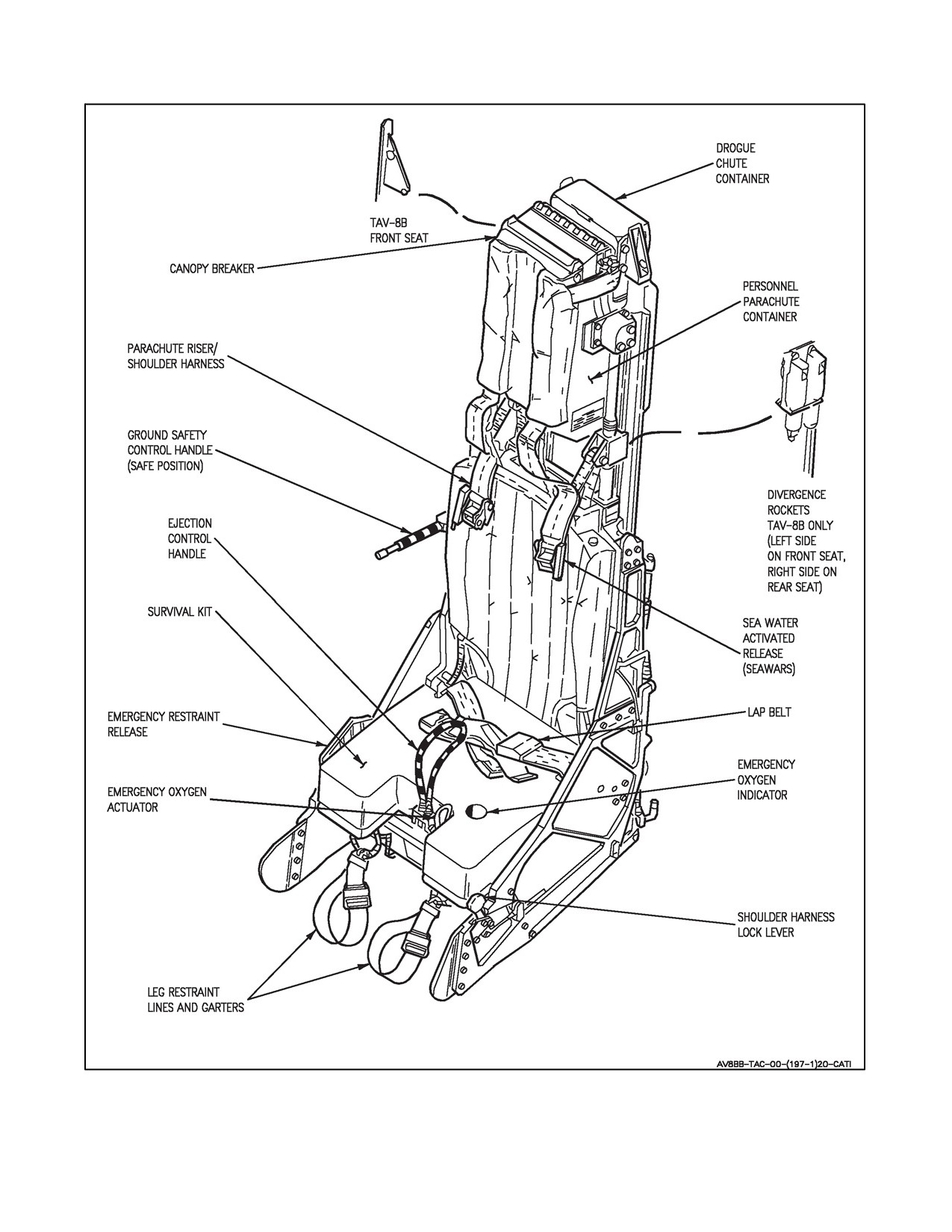
A1-AV8BB--NFM--000
Figure 2-27. Ejection Seat
2-93
ORIGINAL
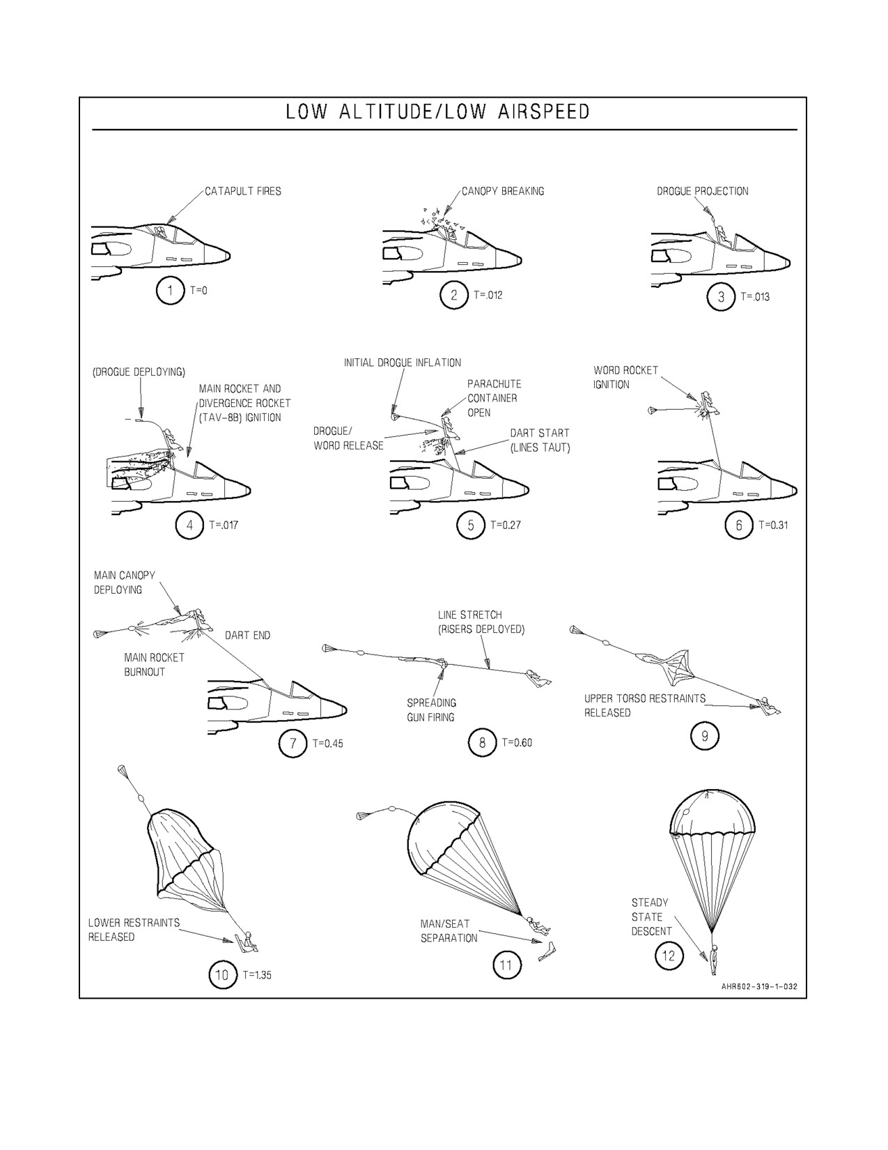
A1-AV8BB--NFM--000
BELOW 225 KNOTS (180 KNOTS WITH IACC 658), (165 KNOTS WITH AFC--449) AND BELOW 7000 FEET
Figure 2-28. Ejection Sequences (Sheet 1 of 4)
ORIGINAL
2-94
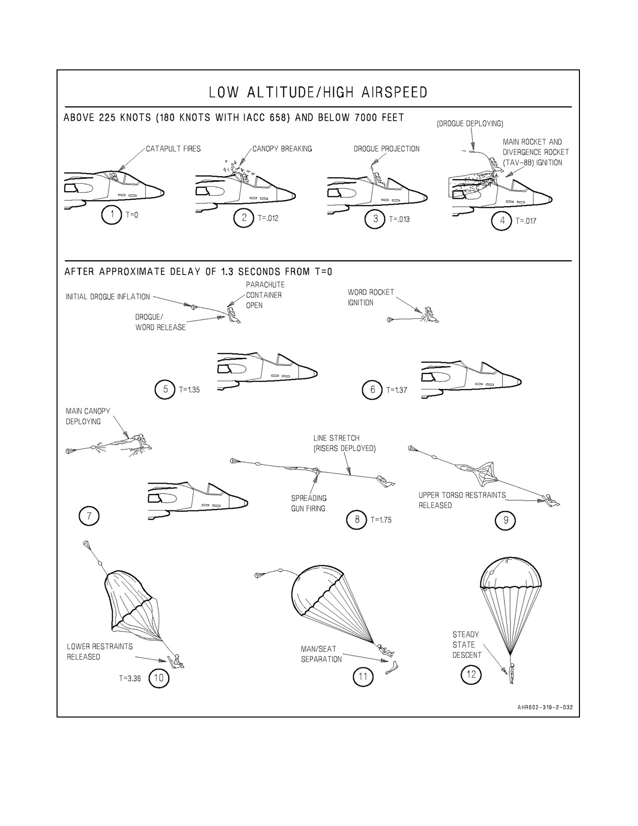
A1-AV8BB--NFM--000
Figure 2-28. Ejection Sequences (Sheet 2)
2-95
ORIGINAL
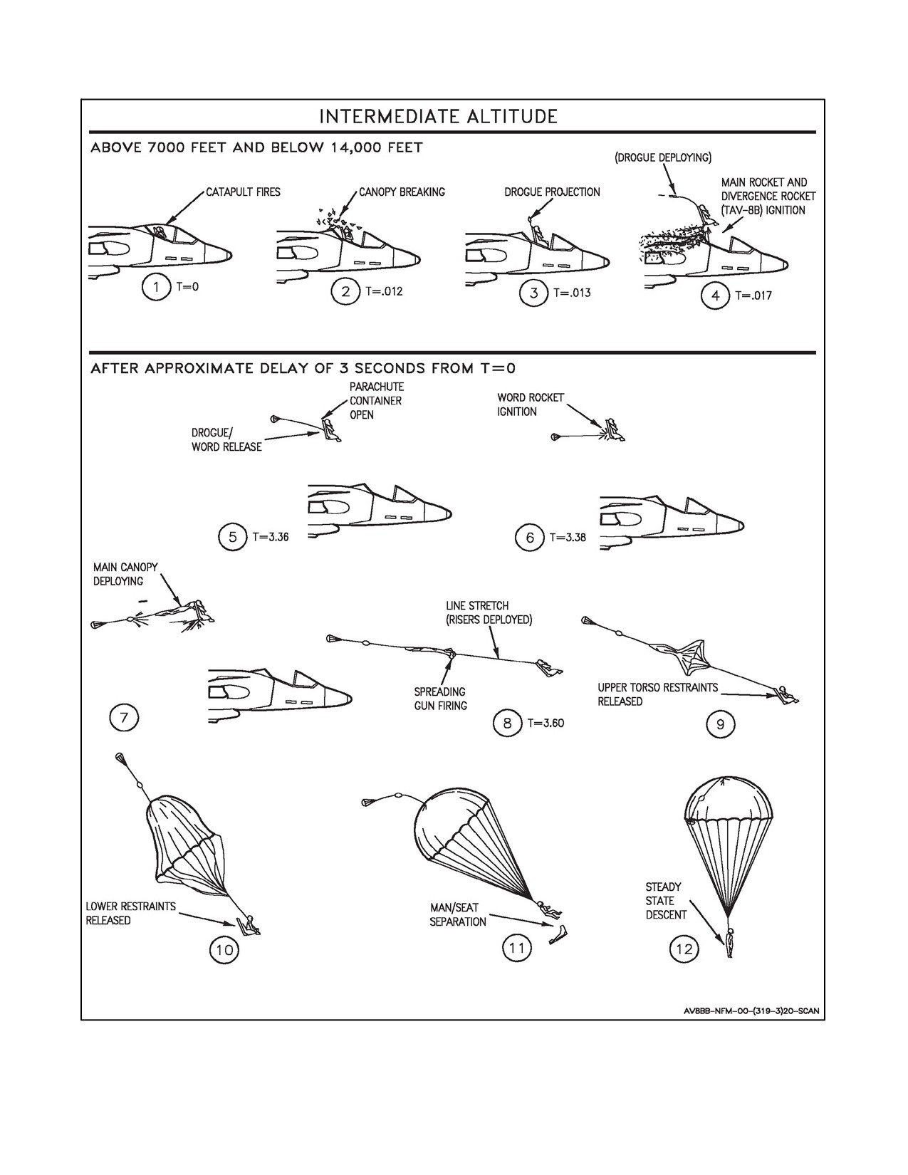
A1-AV8BB--NFM--000
Figure 2-28. Ejection Sequences (Sheet 3)
ORIGINAL
2-96
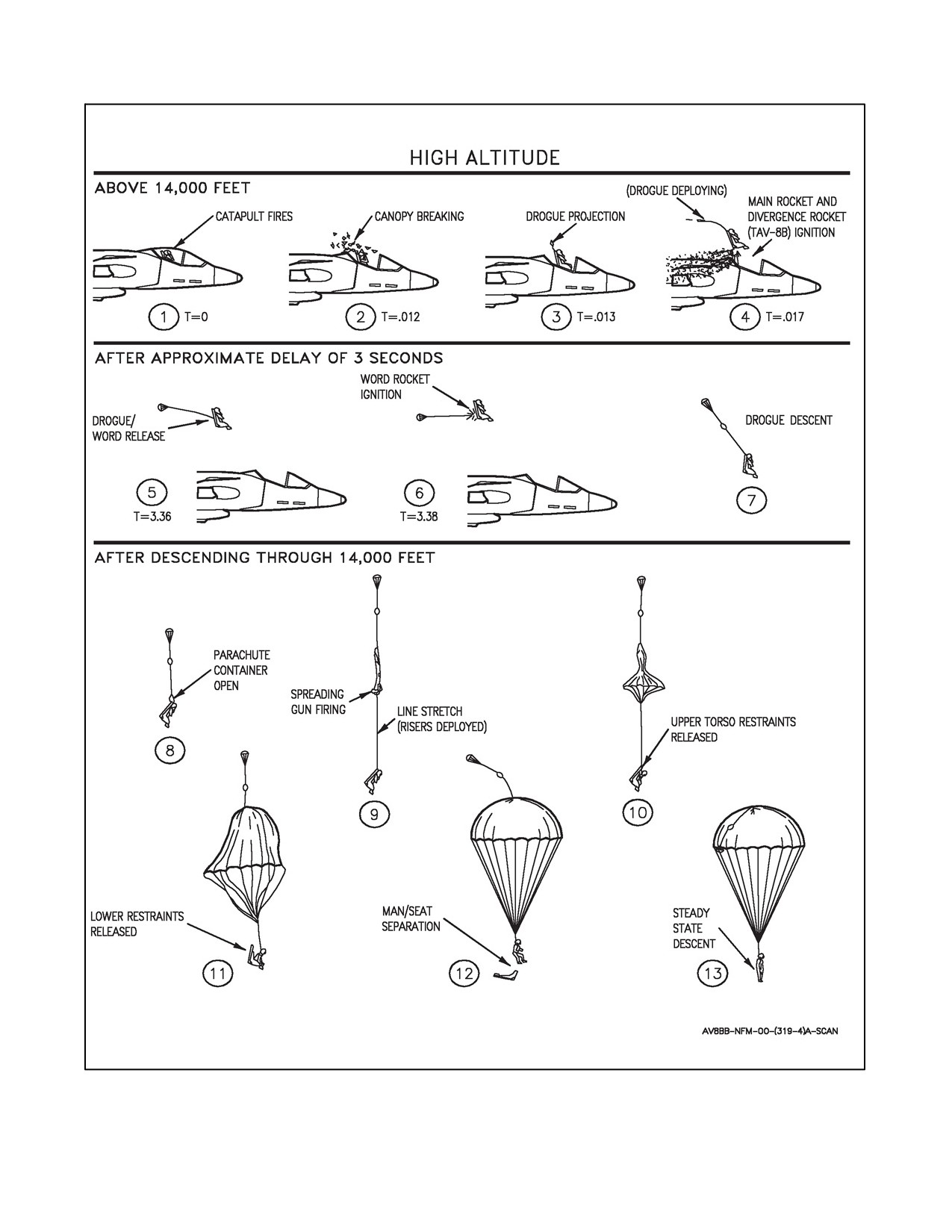
A1-AV8BB--NFM--000
Figure 2-28. Ejection Sequences (Sheet 4)
2-97
ORIGINAL
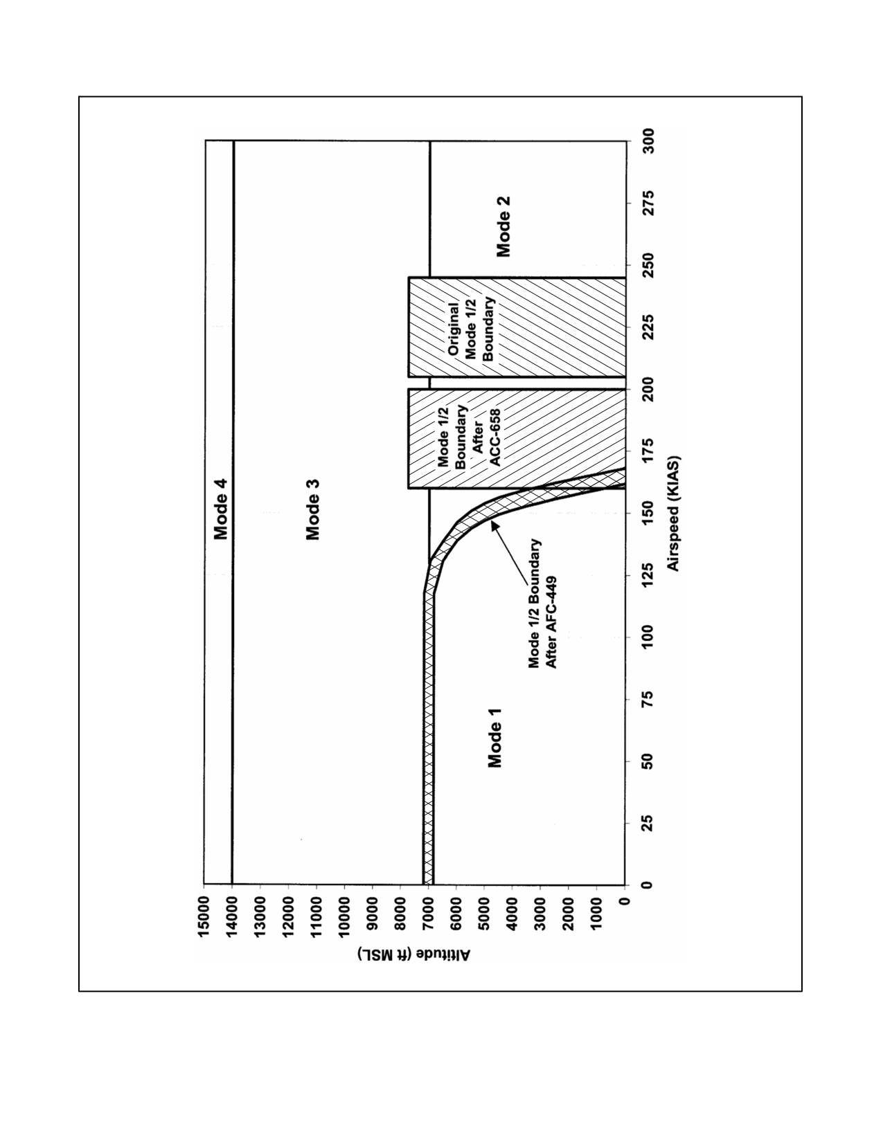
A1-AV8BB--NFM--000
Figure 2-29. T/AV--8B Ejection Seat Modes of Operation
ORIGINAL
2-98
A1-AV8BB--NFM--000
2.24.4 Pilot Harness and Seat Harness
The pilot’s harness is a combined parachute harness and restraint garment that is put on before entering the cockpit.
When seated, the pilot’s upper harness is connected to the parachute risers by two Koch connectors, and the lower
harness is connected to the two lap belt connectors. The parachute risers and lap belts remain in the aircraft between
flights.
2.24.5 Shoulder Harness Inertia Reel and Gas Generator
A shoulder harness inertia reel and gas generator is installed on the ejection seat. The inertia reel provides the pilot
with capability for locking his shoulder harness to prevent forward motion and also capability for unlocking his
shoulder harness so that he is free to move forward or aft. In addition, the reel will lock automatically, although the
shoulder harness lock lever is in the unlocked position, whenever high g conditions are encountered. The shoulder
harness gas generator operates only during ejection to pull the shoulder straps back so the pilot is positioned for
ejection. The seat also contains an inertia reel guillotine which when activated, severs the shoulder straps to free the
pilot’s upper torso automatically following ejection, or manually when the emergency restraint release handle is
operated during manual separation or emergency ground egress.
2.24.5.1 Shoulder Harness Lock Lever
Located on the seat bucket just outboard of the pilot’s lower left thigh, the shoulder harness lock lever has two
positions,forwardandaft. Theforward isthemanuallocked positionand preventsforward movementoftheshoulder
harness. The aft position is the unlocked/auto lock position, and forward movement is provided except for high g
conditions. Once locked automatically while in the aft position, the harness can be unlocked by cycling the handle
forward and then aft to the unlocked position.
2.24.5.2 Seat Adjust Switch
The seat adjust switch, on the left console above and outboard of the fuel panel, operates the actuator. The operating
cycle is 30 seconds on and 1 minute off to permit cooling.
2.24.6 Leg Restrainers
The leg restraining system is designed to prevent leg flailing during ejections. The system consists of leg garters, leg
garter straps, and ratchet/snubbing assemblies. The leg garters are adjustable and worn at the mid--calf on each leg.
The garters are hooked to a key on each leg strap, and the garters can be detached from the keys and thus they can
be worn to and from the aircraft. The leg garter straps are routed through the leg garter keys so that the legs will be
restrained against the front of the seat when the straps are pulled taut during ejection. The garter straps are routed
through the ratchet/snubbing assemblies on the front of the seat, through the garter keys, and the upper end of the
garters are secured to locking devices in the ratchet/snubbing assemblies by releasable pins. The pilot can increase
strap length for adequate leg motion by pulling out a springloaded release pin on the ratchet/snubber assembly and
then pulling the strap forward. To decrease strap length, the pilot reaches behind the ratchet/snubber assembly and
pulls the strap through. During the ejection sequence, the straps are pulled back through the ratchet/snubber
assemblies, drawing the pilot’s legs aft and restraining them against the seat structure. As the seat travels upward,
tension is applied to the rip stitch. The lanyards are sheared at the rip stitch, severing the connection between seat
and aircraft. At seat/man separation, as the pilot is extracted from his seat by his parachute, the pins in the
ratchet/snubber assemblies are released to free the pilot’s legs. Operation of the emergency restraint release handle
also releases the pins during manual separation and emergency ground egress.
2.24.7 Ejection Control Handle
The ejection control handle, on the forward seat pan, is mechanically connected to the ejection initiation system.
When the handle is pulled fully upward, the ejection sequence is initiated. After actuation, the handle remains
attached to the seat and the handle must be released before or during man/seat separation. Initiators will fire before
maximum handle travel of approximately 3.25 inches so that the pilot can retain his grip and prevent arm flailing
when exposed to windblast.
2-99
ORIGINAL
A1-AV8BB--NFM--000
2.24.8 Ground Safety Control Handle
Theground safety control handleon theright forward sideoftheseat at shoulder level provides ameans forsafetying
or arming the seat. The armed position is down and back against the seat. The safetied position is up and forward
away from the seat. Prior to moving the handle from one position to the other, a handle lock must be released. The
lock is released by pulling on the spring--loaded lower end of the handle.
2.24.9 Post Ejection Sequencing System
The post ejection sequencing system includes all gas operated and cartridge actuated devices required to initiate the
sequencing functions of the four post ejection modes. The system includes a parachute container opener assembly
which is activated by gas pressure from either the 7,000 foot or 14,000 foot aneroid activated initiators or gas pressure
from the man/seat separation initiator. When activated, the opener assembly opens the container so that the personnel
parachute can be deployed. The system also includes the wind oriented rocket deployment (WORD) rocket which
is mounted on the back of the seat and is connected on one end to the WORD bridle assembly (personnel parachute
withdrawal line) and on the other end to the drogue bridle assembly (drogue suspension lines). The WORD rocket
is attached to theback ofthe seat by means of theWORD motor/droguerelease assembly. The WORD motor/drogue
release assembly actuates to release the rocket motor (and with it the personnel parachute withdrawal line) from the
back of the seat during all four modes of operation of the post ejection sequencing system. After release, the WORD
rocket motor is then fired by inertia (I -- WORD deployment sequence) for low speed ejections, or the WORD rocket
motor is fired by the pull of the drogue suspension lines (drogue -- WORD deployment sequence) for higher speed
ejections. See Figure 2-28 for each of the four modes of operation of the post ejection sequencing system.
2.24.10 Parachute
The personnel parachute system includes a WORD bridle assembly (parachute withdrawal line), riser assemblies
with snubbing lanyards which initiate the ballistic spreading gun and initiate man/seat separation, a spring--loaded
internal pilot parachute, a main canopy, a ballistic spreading gun, and an override disconnect assembly. Parachute
deployment begins, propelled via the WORD bridle, by force generated by means of drogue--WORD, I--WORD, or
in the event of WORD bridle failure, by the internal pilot parachute. When the main canopy and suspension lines
are fully deployed, line stretch pulls a lanyard which, in turn, exerts tension on a spring--loaded firing pin in the
ballistic spreading gun assembly. The pin is withdrawn, igniting the spreading gun cartridge. Cartridge energy expels
14 pistons which, in turn, expel 14 slugs, attached to alternate suspension lines, in a 360° pattern, thus spreading the
main canopy. Should the spreading gun cartridge fail to fire, continued pull on the firing lanyard will remove a
piston--retaining band, freeing the pistons, slugs and suspension lines to allow conventional canopy inflation.
Theparachuteisa28foot flatcanopy typeparachutewithalternating coloredpanels (white,olivegreen,international
orange, and sand shade). The parachute is rated for suspension of 100--300 pounds with a descent rate of 13.3 to 23.1
feet per second.
2.24.10.1 Four--Line Release System
With ACC--667 PART 2, the four--line release system is a feature used to reduce canopy oscillation and provide
limited forward motion and directional control of the parachute during descent. Suspension lines 1, 2, 27 and 28 are
rigged so that when the four--line release lanyards are pulled sharply down, the lines are released from the left and
right connector links. Release of the lines allows four gores of the canopy to billow free creating a vent at the rear
of the canopy. Canopy oscillations are reduced or eliminated upon actuation of the four--line release system. The
escape of air through the vent imparts a horizontal motion to the parachute assembly. The two four--line release
lanyards, one attached to each rear riser, are used for directional control.
2.24.11 Sea Water Activated Release System
On TAV--8B, AV--8B 162721 and up, an automatic backup method of releasing the parachute canopy when landing
in sea water after an emergency egress is installed. The sea water activated release system (SEAWARS) system
consists of two releases mounted outboard of the Koch connectors on the parachute risers. Each release contains an
electronics package (sensor), battery, cartridge, and canopy release fitting. Immersion in sea water activates the
sensors which mechanically release the parachute risers from the pilot’s restraint harness. With SEAWARS installed,
the normal procedures for connecting and releasing the Koch fitting are unchanged.
ORIGINAL
2-100
A1-AV8BB--NFM--000
2.24.12 Man/Seat Separation System
After ejection, as aerodynamic drag is imposed on the personnel parachute, tension on a lanyard sewn to the right
hand and left hand riser assemblies fires a man/seat separation initiator, producing gas pressure which is directed to
an inertia reel guillotine. The guillotine severs two inertia reel shoulder straps, releasing restraint on the pilot’s upper
torso. Simultaneous actuation of the man/seat separation mechanical linkage by the right hand and left hand riser
assemblies lanyard releases the survival kit and the pilot from the ejection seat. The pilot and survival kit are then
withdrawn from the seat assembly by the aerodynamic drag on the personnel parachute.
2.25
MANUAL SEPARATION AND EMERGENCY GROUND EGRESS
2.25.1 Manual Separation
If any component should fail during any of the four automatic ejection modes, the occupant can operate the man/seat
separation system manually. By operating the emergency restraint release handle, the man/seat separation initiator
fires and the following sequence takes place: the inertia reel guillotine actuates to sever the inertia reel shoulder straps,
thetorquereleaserod rotatesto releasethesurvivalkit andleg restraints,theWORDmotoractuatesand theparachute
container is opened. The personnel parachute then deploys, aided by either the drogue--WORD or I--WORD
sequence, depending upon airspeed at the time the emergency restraint release handle is pulled.
2.25.2 Emergency Ground Egress
During emergency ground egress when it is desired to evacuate the cockpit with the survival equipment, as part of
the procedure the pilot must actuate the emergency restraint release handle in order to release the survival kit and leg
restraints.
2.25.3 Emergency Restraint Release Handle
The emergency restraint release handle on the seat bucket just outboard of the pilot’s right lower thigh is actuated
by first squeezing the handle and then pulling up and aft. Once actuated, the handle locks up in the released position
and will remain there until the handle is reset. During ground egress when the handle is pulled the following occurs:
the ejection initiation system is safetied, the inertia reel shoulder straps are severed, the leg restraint straps and
survival kit are released, the main parachute container is opened and the WORD motor/drogue release assembly is
actuated. During manual separation after ejection, the above occurs plus the WORD rocket motor fires to deploy the
main parachute.
2.25.4 Survival Package
The survival package is attached to the survival kit seat pan through a lanyard system which allows the package to
fall free of the seat pan, yet remain in close proximity to the pilot. When the survival package is manually released
by actuating the survival package release, it is allowed to fall approximately 12 feet, where its fall is snubbed by a
lanyard which causes inflation of the life raft. The package then falls another 13 feet below the raft, giving stability
to the raft during parachute descent. The survival package contains: a life raft, signal devices, medical aids and
miscellaneous post ejection survival aids.
The following is a representative list of items contained in the survival package:
Cord, (Nylon), Fibrous Type I 50 feet.
Signal, (Flare), Smoke and Illumination, MK--124 MOD 0.
Sea (Dye) Marker, Fluorescent 2.
Sponge, (Bailing), Cellulose Type II, Class 2.
SRU--31/P Survival Kit, Packet (#1) (Medical).
SRU--31/P Survival Kit, Packet (#2) (General).
SRU--31A/P Optional.
Bag, Drinking Water (50 ml).
Opener, Can, Hand.
Ground/Air Emergency Code Card.
2-101
ORIGINAL
A1-AV8BB--NFM--000
Blanket, Combat Casualty, (3 oz).
Clear Vinyl Envelope 2 00--334--4120 or Equivalent.
Beacon Set, Radio AN/URT--140.
Liferaft, Inflatable.
2.25.4.1 Survival Package Release
The survival package release is a loop on the back, right side of the survival kit. Pulling the loop releases the survival
package from the seat pan.
2.25.5 Emergency Oxygen
The emergency oxygen supply is a completely self--contained unit, attached to the bottom of the seat pan, that
provides 100 cubic inches of breathing oxygen. It can be operated either automatically (during ejection) or manually
if a failure occurs in the aircraft main oxygen system. Automatic emergency oxygen control is provided by a lanyard
assembly located on the underside of the seat panel left thigh support and is connected to the seat catapult cartridge
manifold. Upon upward movement of the seat panel, as in an ejection, automatic actuation is provided. A pressure
gauge, visible through the cutout on the forward left hand side of the seat cushion, should register 1,800 psi (needle
in the green area) with full bottle. Duration of emergency oxygen supply is approximately 15 minutes, depending
upon altitude (the higher the altitude, the longer the duration), since oxygen is delivered by the mask regulator only
upon demand. Oxygen from the bottle is supplied by release of a valve in the pressure regulator at the forward left
edge of the survival kit. Two keeper yokes on the valve shaft keep the valve in the closed position until emergency
oxygen is required. One of these yokes is attached by a cable to the manual release (emergency oxygen actuator),
which is stowed on the forward left--hand inboard edge of the survival kit. The other is attached by cable, through
a quick disconnect fitting to a lanyard attached to the ejection seat catapult cartridge manifold. Either cable will
dislodge a yoke and actuate the emergency oxygen supply valve to provide oxygen from the bottle and shut off the
main aircraft supply. When the seat is ejected or the pilot leaves the aircraft still attached to his survival gear, the cable
attached to the catapult cartridge manifold is pulled and emergency oxygen is supplied automatically. Manually
pulling the emergency oxygen actuator provides emergency oxygen at any time.
2.25.5.1 Emergency Oxygen Release
Manual emergency oxygen release (emergency oxygen actuator) is provided by a handle/pull ring located on the
inboard side of the left thigh support. An upward pull on the handle provides emergency oxygen to the pilot in the
event of a failure in the aircraft main oxygen system or a failure of the emergency oxygen actuation system during
ejection. Once activated, the emergency oxygen supply can not be turned off.
2.26
EMERGENCY LOCATOR BEACON (AN/URT--33 OR AN/URT--140 AFTER ACC--689)
An emergency locator beacon on top of the seat pan, is automatically actuated during emergency egress via the
auto--actuation lanyard that is connected to the radio, emergency oxygen supply, and cockpit deck fitting.
2.26.1 Canopy/Interseat Sequencing System
A canopy/interseat sequencing system is provided to allow dual or single ejection initiated from either cockpit
depending on the position of the ejection sequence selector.
2.26.1.1 Ejection Sequence Selector
Through use of the ejection sequence selector on the left side of the rear main instrument panel (foldout FO--2), six
modes of ejection sequencing can be selected. The selector has three positions: DUAL, FWD and AFT/SOLO. The
DUAL position is with the selector handle aligned horizontally. The FWD position is with the handle in the 45°
counterclockwise position from the horizontal. The FWD position can only be maintained by use of a collar placed
around the shaft of the handle. The AFT/SOLO position is with the handle aligned vertically. If the handle is released
at any point other than the AFT/SOLO position, the handle will return to the DUAL position.
ORIGINAL
2-102
A1-AV8BB--NFM--000
DUAL
Dual ejection results from ejection initiation in either cockpit. Rear seat ejects
(horizontal)
first, followed by front seat after a 0.4 second delay.
FWD
Dual ejection results from ejection initiation in front cockpit. Rear seat ejects
(45° ccw)
first, followed by front seat after 0.4 second delay.
Single ejection results from ejection initiation in rear cockpit. Front cockpit can
then eject solo, with a 0.4 second delay.
AFT/SOLO
Dual ejection results from ejection initiation in rear cockpit. Rear seat ejects first,
(vertical)
followed by front seat after a 0.4 second delay.
Single ejection results from ejection initiation in front cockpit, with a 0.4 second
delay. Rear cockpit can then eject solo.
2.27
ENVIRONMENTAL CONTROL SYSTEM
The environmental control system (ECS) provides conditioned air and pressurization for the cockpit and avionics
equipment. The ECS also provides conditioned air to the windshield defog, anti--g and canopy seal systems. See
Environmental Control System, foldout section, for environmental control system schematics.
2.27.1 ECS Air Sources
2.27.1.1 Bleed Air
Thenormal sourceofECS airis the 6th--stageengine bleed air except for radarequipped aircraft which use8th--stage
engine bleed air. Through a series of manifolds and valves this air is cooled and mixed to reduce temperature and
pressure to usable levels.
2.27.1.2 Ram Air
Asecondary sourceofECS airis ramairwhichcan beused toventilatethecockpit andprovidecoolingairtoavionics
equipment requiring forced air cooling.
2.27.2 Cockpit Air Conditioning
High temperature engine bleed air is routed through the cabin pressure regulator and shutoff valve and venturi to the
primary heat exchanger where it is cooled. The cooled output of this heat exchanger is applied to the compressor
turbine. Thecompressed airis run through thesecondary heat exchanger, and then expanded in the expansion turbine
section, resulting in cold air that is mixed with hot bleed air from the cabin temperature control valve. This valve is
modulated by the temperature controller on the ECS panel. The conditioned air passes through a water separator and
vent/defog changeover valve to the cockpit ECS louvers and windshield defog ducts.
Ram air across the heat exchanger is used for initially cooling the bleed air. The ram air discharge from the heat
exchangers is routed to the engine inlet or vented to the ECS bay on nonradar aircraft or vented overboard on radar
aircraft depending on the flight conditions encountered. At high air speeds the ram air is vented to the ECS bay or
vented overboard as applicable. At lower airspeeds and during ground operation airflow across the heat exchangers
is augmented by the engine turbine fans which pull ambient air across the heat exchangers into the engine inlet.
2.27.2.1 Temperature Management
The pilot can control cockpit temperature by selecting either a manual (MAN) mode or automatic (AUTO) mode with
the temperature controller on the ECS panel.
In the MAN mode, holding the cabin temperature control knob to the COOL or WARM settings applies a control
signal directly to the cabin temperature control valve to open or close the valve as desired. The signal is applied to
thevalveas long as theknob is held in theCOOL orWARM setting. In this mode, thecabin temperaturecontrol knob
is spring loaded to the center position and returns to the center position when released.
In the AUTO mode the temperature is electronically regulated by the cabin temperature control. The control
continuously monitors onboard temperature sensors and compares the sensed temperature to the selected
2-103
ORIGINAL

A1-AV8BB--NFM--000
temperature. If an imbalance exists, too hot or too cold, a signal is applied to position the cabin temperature control
valve to maintain the selected temperature. In this mode the cabin temperature control knob, when released, remains
in the position selected.
2.27.2.2 Temperature Controller
The temperature controller is on the ECS panel.
AUTO
With knob in automatic section, counterclockwise rotation decreases cockpit and
windshield defog air temperature. Clockwise rotation increases temperature. In
AUTO mode, temperature is electronically regulated. This is the normal mode of
operation. In AUTO mode, knob will remain in position selected when released.
MAN
In MAN mode, knob is springloaded to the center position. With knob in manual
section, counterclockwise rotation increases cockpit air and windshield defog
temperature. Clockwise rotation decreases temperature. In MAN mode
temperature is controlled through direct operation of the cabin temperature
control valve.
Note
Should chunks oficeand/orsnow bedetected discharging from thecockpit
ECS louvers, a higher cockpit air temperature should be selected to restore
the system to normal operation. The ice/snow condition is caused by too
cold a selection of the temperature controller resulting in a freeze--up
condition of the water separator coalescer and operation of the internal
coalescer bypass relief.
2.27.3 Defog System
The defog system uses the same air for defogging as passes to the cockpit ECS louvers. When defog is selected, a
larger portion of airflow is diverted from the pilot to the windshield defog ducts. Temperature of the defog air is
automatically increased when MAX DEFOG is selected and the temperature controller is in the AUTO mode.
Temperature of the defog air may be increased or decreased by the pilot by changing the temperature controller
position in either the AUTO or MAN mode.
2.27.3.1 Defog Switch
The defog switch, labeled CABIN, is on the ECS panel.
NORM
The vent/defog changeover valve is energized to provide the majority of
conditioned airflow to the pilot.
DEFOG
Increased airflow is directed to windshield. Vent/defog changeover valve
deenergized.
MAX
Increased airflow is directed to windshield at an increased temperature. MAX
DEFOG
DEFOG position inoperative with temperature in MAN mode.
Note
For extreme windshield fog conditions, place defog switch to MAX
DEFOG and increase the temperature in the AUTO range on the
temperature controller.
ORIGINAL
2-104

A1-AV8BB--NFM--000
2.27.3.2 Defog Shutoff Valve
A defog shutoff valve provides for increased pilot cooling during periods of low system pressure (e.g. engine at idle)
by directing all system airflow to the ECS louvers. A pressure switch monitors the primary heat exchanger outlet
pressure and provides a signal to close the defog shutoff valve when pressure is less than 20 psi.
2.27.3.3 Windshield Overheat Caution Light
When the windshield temperature limit of the defog air is exceeded, the WSHLD overheat caution light comes on.
The WSHLD caution light is on the caution/advisory light panel and operates in conjunction with the mastercaution
light. When the WSHLD overheat caution light comes on power is automatically supplied to the cabin temperature
control valve to drive it to the closed (low temperature) position.
2.27.4 Cockpit Pressurization
Cockpit pressure scheduling is maintained by the cabin pressure regulator/discharge valve on the forward cabin
bulkhead. From sealevel to 8,000 feet altitudethecockpit is unpressurized. Between altitudes of8,000 feet to 23,000
feet the system maintains a constant cockpit pressure altitude of 8,000 feet. At altitudes above 23,000 feet, the cockpit
pressure regulator maintains a constant 5 psi pressure differential greater then ambient pressure. The cockpit pressure
can be dumped by setting the cockpit pressure switch, on the ECS panel, to DUMP. On the TAV--8B the air
communication duct connects the two cockpits for pressure equalization and air circulation.
2.27.4.1 Safety Relief Valve
If the cockpit pressure regulator/discharge valve malfunctions the cockpit safety relief valve will open to vent excess
cabin pressure. The valve also provides negative pressure relief. This occurs during rapid aircraft descent. Normal
operation of the system cannot always react to change cabin pressure as fast as the aircraft can descend. When this
occurs, the safety relief valve will open and allow ambient pressure to enter the cabin to equalize pressure.
2.27.4.2 Cockpit Altimeter
A cockpit altimeter is mounted to the right of the caution light panel on the main instrument panel (see cockpit, foldout
section) and indicates cockpit pressure altitude from 0 to 50,000 feet.
2.27.4.3 Cockpit Pressure Switch
The cockpit pressure switch, labeled PRESS, is on the ECS panel on the right console.
NORM
Pressure regulator and shutoff valve open, with normal conditioned air and
pressure provided to system.
DUMP
Cabin safety/dump valve control valve energized to dump cockpit pressure.
Pressure regulator and shutoff valve still open, supplying normal conditioned air
to the crew station.
RAM
Cabin pressure is dumped as in the DUMP position, and pressure regulator and
shutoff valve energized to shut down engine bleed air to system. Nose ground
cooling/ram air valve opens to supply ram air to entire system. Switch position
also energizes the ground cooling fan to facilitate flow of ram air to forward
avionics equipment.
2.27.5 Radar Waveguide Pressurization
On radar aircraft the forward ECS system provides positive pressure to the radar waveguide to prevent arcing at high
altitude. The cooled output of the secondary heat exchanger is split and a portion is provided for waveguide
pressurization. The ECS system provides pressure regulated, clean, dry air to the waveguide.
2-105
ORIGINAL
A1-AV8BB--NFM--000
2.27.6 Anti--g System
With the cockpit air conditioning and pressurization system operating, the anti--g suit remains deflated up to
approximately 1.5g’s. Above this acceleration, the air pressure applied to the suit increases in proportion to increasing
g’s. While acceleration is constant, the suit remains inflated at a constant pressure and, as acceleration decreases, the
suit will deflate in proportion to the decrease in g’s. A manual inflation button in the anti--g suit valve on the aft left
console allows the pilot to manually inflate the suit for purposes of checking the system or for fatigue relief. The
anti--g system is inoperative with the cockpit pressure switch in the RAM position.
2.27.7 Canopy Seal
The canopy seal inflates automatically on takeoff when the canopy seal control valve deenergizes open with
weight--off--wheels. The valve energizes closed and vents canopy seal pressure with weight--on--wheels. With the
cockpit pressure switch in the RAM position, the canopy seal is inoperative.
2.27.8 Cockpit Equipment Cooling
Cockpit conditioned air is also used to cool cockpit installed avionics equipment. A cooling fan, which operates
continuously, pulls cockpit air through the following cockpit installed equipment: ODU, HUD, DDI(s), and on
non--radar aircraft the DC.
2.27.8.1 Crew Station Cool Caution Light
Failure of the cockpit equipment cooling fan causes the CS COOL caution light to come on. The light is on the
caution/advisory lights panel and operates in conjunction with the master caution light. To protect the avionics
equipment should the CS COOL light come on, the cockpit temperature should be adjusted to a setting as cold as
practical and any unneeded avionics equipment should be turned off.
2.27.9 Forward Equipment Cooling
2.27.9.1 Normal Operation
On non--radar aircraft part of the cold expansion turbine discharge air is combined with cockpit conditioned air and
routed to a plenum for normal INS cooling. Discharge air from the cabin pressure regulator valve is ducted into the
nose cone to cool the angle rate bombing system (ARBS) which contains internal cooling fans.
On radar aircraft the bleed air output from the primary heat exchanger is mixed with the cold air output of the
expansion turbine by way of the avionics cooling valve. This modulating valve is driven by the airflow
temperature/sensor controller and is positioned to maintain a 40 °F supply temperature to the forward avionics
systems (radar, INS, FLIR). The radar system is also cooled by a liquid cooling system. See paragraph 2.27.11.
2.27.9.2 Emergency/Ground Operation
On non--radar aircraft, when the aircraft is on the ground, a ground cooling fan operates through the
weight--on--wheels switches to provide cooling air to forward equipment. The ground cooling fan operates in flight
when the RAM position of the cockpit pressure switch is selected. When RAM is selected, ram air is supplied to the
entire system, except for the canopy seal and anti--g system.
On radar aircraft the ground cooling fan also operates through the weight--on--wheels switch to provide cooling air
to the INS, FLIR, and radar. In flight, when the temperature sensor/controller detects an out of tolerance condition
(FWD BAY caution) or the RAM position of the ECS pressure switch is selected, the ground cooling fan operates
to provide cooling air to the forward equipment, and the emergency ram air valve is opened to provide ram air to the
INS cooling plenum and to the cockpit. The canopy seal, anti--g system, and radar waveguide pressurization system
are not affected.
2.27.9.3 Forward Equipment Bay ECS Switch
On radar aircraft the forward equipment bay ECS switch, labeled FWD EQUIP, is on the ECS panel.
NORM - Switch is spring loaded to this position. System operation is normal.
RESET - Restarts system after temporary malfunction and shutdown.
ORIGINAL
2-106
A1-AV8BB--NFM--000
2.27.9.4
Forward Equipment Bay Caution Light
On radar aircraft the FWD BAY caution light comes on whenever the airflow temperature sensor/controller senses
inadequatecooling, temperatureout oftoleranceand/orlow orno system airflow. Thelight is on thecautionadvisory
light panel and operates in conjunction with the master caution light.
2.27.10 Aft Fuselage Equipment Cooling
2.27.10.1 Normal Operation
High temperature and pressure engine bleed air is routed through the aft equipment pressure regulator and shutoff
valve. This valve functions automatically but can be controlled manually by the EQUIP switch (non--radar aircraft)
ortheAFT EQUIPswitch (Radaraircraft)locatedon theECS panel.With thevalveopen,thebleedairpassesthrough
a heat exchanger cooled by ram air from the intake at the base of the vertical stabilizer. From the heat exchanger, the
air is expanded in a turbine which drives a fan in the ram air exhaust. The fan induces ram air flow through the heat
exchanger, particularly during ground operation. The discharged cool air from the turbine is warmed to the proper
temperature by mixing it with hot bypass bleed air which is regulated by a thermostatically controlled temperature
control valve. The mixed air is then routed to the aft equipment cooling plenum for distribution to avionics
equipment.
2.27.10.2 Emergency/Ground Operation (Radar Aircraft)
On the ground with engine not running, or in flight and aft equipment cooling system pressure is lost or system shut
down, the avionics auxiliary cooling fan will operate to supply ambient airto theaft equipment cooling plenum. The
cooling fan turns on automatically (assuming electrical power is available) whenever any of the following occurs:
main system turned off, turbine inlet pressure too high, bleed air overpressure, incorrect two way valve position,
equipment delivery air temperature outside limits of control system, incorrect auxiliary cooling valve position. Any
of the above actions result in the avionics auxiliary cooling valve opening to allow ambient air from the ram air duct
to go to the aft equipment cooling plenum via the cooling fan.
2.27.10.3 Aft Equipment Bay ECS Switch
The aft equipment bay ECS switch, labeled EQUIP on non--radar aircraft or AFT EQUIP on Radar aircraft, is on the
ECS panel.
OFF - The equipment pressure regulator and shutoff valve is energized close to shutdown the system.
ON - A neutral switch position. This is normal position for switch.
RESET - Restarts system after temporary malfunction and shutdown.
2.27.10.4 Aft Equipment Bay Caution Light
The AFT BAY caution light comes on whenever the cooling fan is operating (except on the ground) and/or in the
emergency/ground cooling mode. The light is on the caution/advisory light panel and operates in conjunction with
the master caution light.
2.27.11 Liquid Cooling System
The aft ECS system is an integral part of the radar liquid cooling system. The liquid/air heat exchanger extracts heat
from the liquid coolant flowing in the closed loop system. A thermostatic temperature control valve set in parallel
with the heat exchanger core, senses coolant temperature and mixes bypass and core fluid flows to maintain delivery
temperatures to the transmitter at 80 ±10 °F. During normal operation ram air is routed through the transmitter
auxiliary cooling valve through the heat exchange, windmills the transmitter auxiliary cooling fan and is then vented
overboard. During ground operation and/or during periods of low ram air pressure, the transmitter auxiliary cooling
fan is used to draw air through the system.
During abnormal operation, ram air temperature too hot or too cold, conditioned bleed air is applied across the heat
exchanger. This occurs when the ram air temperature switch senses an out of tolerance condition. The conditioned
bleed air is routed through the bypass two--way valve, the heat exchanger, and the transmitter two--way valve to the
aft equipment cooling plenum.
2-107
ORIGINAL
A1-AV8BB--NFM--000
2.28
EMERGENCY EQUIPMENT
2.28.1 Jettison Systems
The jettison systems consist of the emergency jettison system and the selective jettison system.
2.28.1.1 Emergency Jettison Button
The emergency jettison system utilizes the emergency jettison button to jettison all stores and suspension equipment
from BRU--36 bomb racks (bomb rack) on stations 1 through 7. AIM--9 missiles are not jettisoned as normal loading
practice does not install the impulse cartridges in the bomb rack.
The landing gear handle must be up, or the weight must be off the aircraft landing gear, or the armament safety
override switch (inaccessible from cockpit) must be in the override position, to enable the emergency jettison button.
When the landing gear handle is in the UP position, the armament safety override switch will be disengaged if
previously engaged. The emergency jettison button, labeled EMER JETT, is on the landing gear control panel and
is painted with alternating black and yellow stripes. Emergency jettison is performed by pressing the button with the
proper ground interlocks satisfied. All weapons are jettisoned in a safe condition, however, there is no guarantee fuzes
will not arm during release or detonate on impact. Jettison occurs at 50 millisecond intervals starting with stations
1, 4 and 7, then stations 2 and 6, and then stations 3 and 5. Stores are not jettisonable from the outrigger pylons.
On the TAV--8B, an emergency jettison button is provided in the rear cockpit outboard of the landing gear/flaps
control panel. The rear cockpit button parallels operation of the front cockpit button.
2.28.1.2 Selective Jettison
Selective jettison is performed by the selective jettison select knob in conjunction with the selective jettison (JETT)
pushbutton,andinsomecases,inconjunctionwiththestationselectbuttons. Selectivejettison canonly beperformed
with the landing gear handle up and the weight off the aircraft landing gear, or with the armament safety override
switch in the override position. All weapons are jettisoned in a safe condition, however, there is no guarantee fuzes
will not arm during release or detonate on impact. AIM--9 missiles are not jettisonable as normal loading practice
does not install the impulse cartridges in the bomb rack.
On TAV--8B, no selective jettison capability exists from the rear cockpit.
2.28.1.2.1 Selective Jettison Select Knob
The selective jettison select knob on the armament control panel to the left of the station select buttons has rotary
positions STA, STOR, SAFE, CMBT and FUEL, and a center push--to jettison (JETT) pushbutton. The STA and
STOR positions are used in conjunction with the station select buttons. With STA selected, all stores and suspension
equipment hung on BRU--36 bomb racks on selected stations are jettisoned. With STOR selected, jettison is the same
as in the STA position, except that all stores mounted on improved triple ejector racks (ITER) are released while
retaining the ITERs. The CMBT position jettisons all stores, including suspension equipment, suspended from bomb
racks, except that all AIM--9s and suspension equipment are retained. Jettison occurs at 50 millisecond intervals
starting with stations 1, 4 and 7, then stations 2 and 6, and then stations 3 and 5, skipping any AIM--9 station. The
FUEL position jettisons fuel tanks from four stations in pairs, first from stations 2 and 6, then, 50 milliseconds later,
stations 3 and 5. The center JETT pushbutton, when pushed, activates the jettison circuits after the stations and
jettison modes are selected. CMBT/FUEL can be selected before takeoff. If STA/STOR is selected, weapon
programming will be inhibited. The SAFE position prevents any selective jettison.
2.28.1.2.2 Station Select Buttons
The station select buttons are on the armament control panel on the lower left corner of the main instrument panel.
The buttons are numbered 1 through 7 corresponding to the aircraft external stores stations. Pressing a button, or
combination of buttons, selects stations for jettison with the STA and STOR positions of the selective jettison knob.
ORIGINAL
2-108
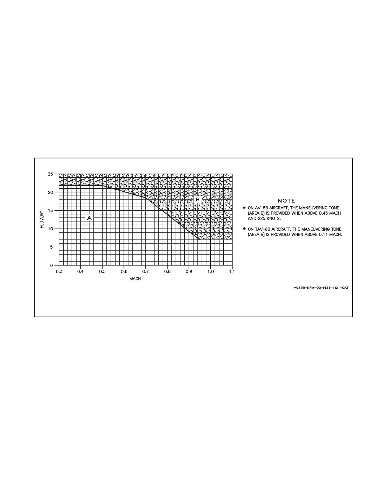
A1-AV8BB--NFM--000
The word SEL is displayed in the station window when the station is selected. Nonselected stations display a dash
in their windows.
2.29
MANEUVERING TONE
An aural maneuvering tone based on AOA and Mach is installed to advise the pilot of the existing aircraft flight
characteristics. A 1,600 Hz--10 pps tone (area B, Figure 2-30) is provided when above 0.45 Mach and 225 knots on
AV--8B aircraft and above 0.11 Mach on TAV--8B aircraft. No tone (area A on the chart) denotes a region where full
high speed stop roll inputs will result in positive aircraft response with no concern for departure. The onset of the
1,600 Hz--10 pps tone marks the maximum turn capability of the aircraft and requires near full back stick. Above the
onset of the 1,600 Hz--10 pps tone (area B on the chart), the roll response is sluggish. Large lateral inputs will result
in a correct initial response followed shortly by a roll reversal. If the roll reversal stall warning cue is ignored and
the roll input maintained, a mild rolling departure will occur. Area B is sometimes characterized by a building wing
rock which will end with a departure. This departure can be avoided and the wing rock stopped by releasing back
stick until the tone stops.
Figure 2-30. Maneuvering Tone (with DEP RES)
2.30
WARNING/CAUTION/ADVISORY LIGHTS AND TONES (TAV--8B AND AV--8B DAY ATTACK
AIRCRAFT)
Thewarning/caution/advisory lightsand displayssystem providesvisual indicationsofnormalaircraft operationand
system malfunctions affecting safeoperation ofthe aircraft. The lights are on various system instruments and control
panels in the cockpit (Figure 2-31).
The red warning lights indicate a hazardous condition requiring immediate action. There are two categories of caution
lights, both of which are yellow. The six priority caution lights are located to the left of the upfront control panel and
below the master caution light. They are L FUEL low, R FUEL low, 15 SEC, MFS, BINGO fuel and H2O. The other
caution lights are on the caution/advisory light panel in addition to the landing gear in--transit lights and the combat
thrust selection light on the water switch panel. All caution lights indicate the existence of an impending dangerous
condition requiring attention but not necessarily immediate action. Illumination of a priority caution light may
require immediate corrective action in certain flight conditions. The green advisory lights indicate safe or normal
configuration, condition of performance, operation of essential equipment, or information for routine purposes. The
advisory lights are on the caution/advisory light panel and on various other panels throughout the cockpit.
2-109
ORIGINAL
A1-AV8BB--NFM--000
Illumination of most warning lights is accompanied by a warning tone in the headset. The exceptions are the GEAR
and landing gear handle lights. Steady illumination of these indicators will not initiate a warning tone. The (hooter)
tone for most warning lights, except LAW, is a 700 to 1,700 Hz sweep for 0.85 second, with an interruption interval
of 0.12 second. The LAW warning tone is a 1,000 Hz tone with an on and off rate of 2 pulses per second for a duration
of 3 seconds and has a priority over the hooter warning tone for the 3 seconds. The hooter warning tone will be shut
off if the cause for the warning light coming on goes away, or by pressing the MASTER CAUTION light. In addition,
the red threat lights on the warning/threat lights panel have special tones associated with their illumination. The
characteristics of these tones are covered elsewhere. Except the CW NOGO and P NOGO, all caution lights on the
caution/advisory light panel flash when they first come on at a flash rate of three to five flashes per second. Pressing
the MASTER CAUTION light causes these caution lights to go to steady illumination, but they will remain on as
long as the cause for the light coming on exists. Except the L FUEL, R FUEL and 15 SEC lights, the priority caution
lights comeon with asteady illuminationand remainon untilthecauseforthelight comingon goesaway. Allcaution
lights that activate the MASTER CAUTION and all priority caution lights are accompanied by a tone (tweedle dee)
which consists of a 0.3 second, 1,900 Hz signal followed by a 0.15 second, 2,600 Hz signal. The steady (750 pound)
L FUEL and R FUEL lights do not activate the tweedle dee tone. The signals are repeated twice for a total time of
0.9 second. No warning/caution/advisory lights are operational until one of the following occurs: GTS started, engine
started, or compass/lights test switch activated (ground alert). A thermostat will cause the lights to flash if they
overheat on the ground. The thermostat is inoperative in flight and there is no indication if the lights overheat.
Dimming of the warning/caution/advisory lights is covered under Lighting, this chapter.
On TAV--8B 163856 and up, AV--8B 163519 and up, the warning tones (hooter) and caution tones (tweedle dee) for
many of the warning and caution lights are replaced by voice warnings. Refer to Voice Warning in this chapter for
list of lights that have associated voice warnings instead of tones.
2.30.1 Master Caution Light
A yellow MASTER CAUTION light, on the main instrument panel to the left of the upfront control panel, comes
on flashing and is accompanied by the tweedle dee tone when any of the caution lights on the caution/advisory light
panel come on, except for the following: CW NOGO and P NOGO. The MASTER CAUTION light goes off when
it is pressed (reset), will cause all flashing caution lights on the caution/advisory light panel to go from flashing to
steady and will silence the caution/warning tones. For voice warnings, pressing the MASTER CAUTION light will
silence only one warning at a time. The stall warning/maneuvering tones are not silenced.
2.31
WARNING/CAUTION/ADVISORY LIGHTS AND TONES (AV--8B RADAR AND NIGHT
ATTACK AIRCRAFT)
Thewarning/caution/advisory lights (Figure2-31)and displays system provides visual indications ofnormalaircraft
operation and system malfunctions affecting safe operation of the aircraft. The lights are on various system
instruments and control panels in the cockpit. Eleven green warning lights located to the right of the upfront control
panel and below the red MASTER WARNING light indicate a hazardous condition requiring immediate action. Six
green priority caution lights are located to the left of the upfront control panel and below the yellow MASTER
CAUTION light. They are L FUEL low, R FUEL low, 15 SEC, MFS, BINGO fuel, and H2O. The other green caution
lights are on the caution/advisory light panel in addition to the yellow landing gear in--transit lights and the green
combat thrust selection light on the water switch panel.
All caution lights indicate the existence of an impending dangerous condition requiring attention but not necessarily
immediate action. Illumination of a priority caution light may require immediate corrective action in certain flight
conditions. The green advisory lights indicate safe or normal configuration, condition of performance, operation of
essential equipment, or information for routine purposes. The advisory lights are on the caution/advisory light panel
and on various other panels throughout the cockpit.
Priority caution lights and the MASTER CAUTION light come on flashing when the cause for the light exists (except
for the 750# L/R FUEL lights and the 15 SEC caution light). The 750# L/R FUEL lights come on steady without
illuminationoftheMASTERCAUTIONlight.PressingtheMASTERCAUTIONlightortheMASTERWARNING
light will reset the priority caution lights and MASTER CAUTION light (except 15 SEC caution light). When the
lights are reset the priority caution lights remain on steady as long as the condition continues to exist and the
MASTER CAUTION light goes off. The 15 SEC caution light comes on flashing after 15 seconds if condition still
exists (the MASTER CAUTION light remains off).
ORIGINAL
2-110
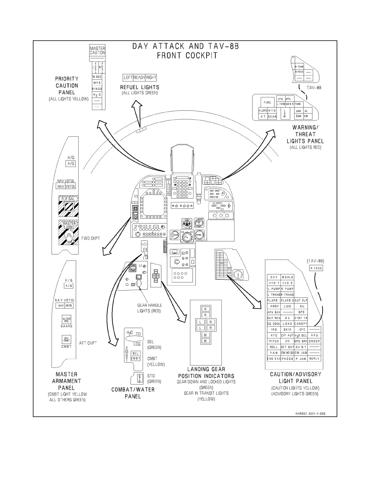
A1-AV8BB--NFM--000
Figure 2-31. Warning/Caution/Advisory Lights (Sheet 1 of 2)
2-111
ORIGINAL
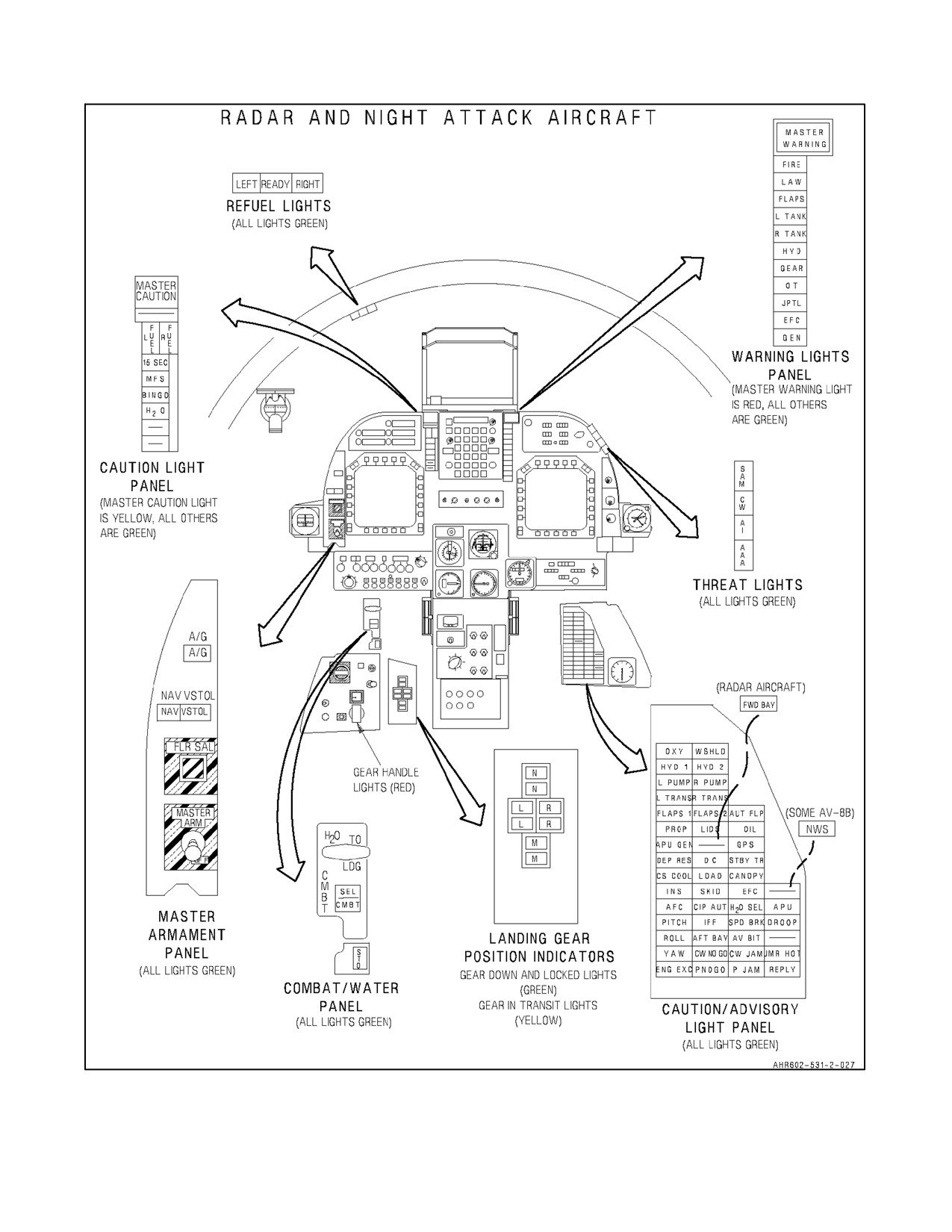
A1-AV8BB--NFM--000
Figure 2-31. Warning/Caution/Advisory Lights (Sheet 2)
ORIGINAL
2-112
A1-AV8BB--NFM--000
The warning lights come on flashing and are accompanied by a voice warning in the headset. Pressing the MASTER
WARNING or MASTER CAUTION light causes the warning light to go steady and halts the voice warning. The
light will remain on as long as the cause for the light exists.
The green threat lights have special tones associated with their illumination. The characteristics of these tones are
covered elsewhere.
Except the CW NOGO and P NOGO, all caution lights on the caution/advisory light panel flash when they first come
on at a flash rate of three to five flashes per second. Pressing the MASTER WARNING or MASTER CAUTION light
causes these caution lights to go to steady illumination, but they will remain on as long as the cause for the light exists.
A thermostat will cause the lights to flash if they overheat on the ground. The thermostat is inoperative in flight and
there is no indication if the lights overheat. Dimming of the warning/caution/advisory lights is covered under
Lighting. Referto VoiceWarning in this chapterforlist oflights that haveassociated voicewarnings instead oftones.
2.31.1 Master Warning and Master Caution Light
The red MASTER WARNING light on the right side of the upfront control unit comes on flashing and is accompanied
by the appropriate voice warning when a warning light comes on. The yellow MASTER CAUTION light comes on
flashing and is accompanied by the appropriate voice warning/audible tone when any caution light on the right
console caution/advisory light panel comes on, except CW NOGO and P NOGO. Either master light will go out when
it or the other master light is pressed (reset), and will cause all flashing warning or caution lights to go from flashing
to steady. Pressing either master light will also silence the current voice warnings. For voice warnings, pressing the
MASTER CAUTION or MASTER WARNING light will silence only one warning at a time. The stall
warning/maneuvering tones are not silenced. Voice warnings are listed in the following table and are stated twice
(e.g., ALTITUDE, ALTITUDE).
2.31.2 Voice Warnings
TAV--8B 163856 and up, AV--8B 163519 and up. Voice warnings are provided in conjunction with certain
warning/caution lights in place of special tones, Figure 2-32. The voice warnings also replace some other tones not
associated with warning/caution lights. The following table provides a list of voice warnings and the associated
warning/caution light, or in the case of no light, the applicable implication. Refer to Warnings, Cautions, and
Advisories in Chapter 12 for implications of the lights.
All voice warnings are presented twice; e.g., the voice warning associated with the FIRE warning light will be
presented as ENGINE FIRE, ENGINE FIRE. In the case of multiple voice warnings, the highest priority voice
warning is sounded first. Before sounding the next voice warning, the priority list is checked to see if any higher
priority warnings have become active. If so, the appropriate voice warning is sounded. If not, the lower priority
warning is then sounded only if it is still active. The purpose of this mechanization is to keep the pilot informed of
the most important failure as well as keep him from being overloaded with unnecessary voice warnings. Once
CAUTION, CAUTION has been sounded, it cannot be repeated for another sounding for a 5--second period. Once
a FUEL LOW, LEFT, FUEL LOW, RIGHT, or BINGO warning is sounded, it will not be permitted to sound again
for a 60--second period.
2.31.3 Ground Proximity Warning System (Trainer with H4.0, Night Attack and Radar Aircraft)
Ground proximity warning system (GPWS) is a safety backup system that alerts the aircrew of an impending
controlled flight into terrain (CFIT) condition. It operates when the MC is powered on and sensor data is available.
The GPWS option window 4 on the ODU with ALT option selected allows the pilot to disable/enable the system.
A colon in the option window indicates selection. GPWS can be deactivated. Deactivation of GPWS starts a 20
minute timer which automatically activates GPWS when the 20 minutes has expired. GPWS provides warnings of
potentially unsafe maneuvering flight conditions, such as excessive bank angles, excessive sink rates, gear--up
landings, floor altitude violations, limited protection against flight into rising terrain, diving flight depending on
flight stages that include takeoff, cruise, or landing, and Altitude Loss During Recovery (ALDR). ALDR includes
theloss ofaltitudedueto persistency timers,pilot reaction,rolling towings level,g--onset, steadystatediverecovery,
variable safety buffer and clearance altitudes for this warning condition. GPWS also provides for terrain
compensation over downward sloping terrain.
2-113
ORIGINAL
A1-AV8BB--NFM--000
VOICE WARNING AND ASSOCIATED WARNING/CAUTION LIGHTS
VOICE WARNING
PRIORITY
WARNING
CAUTION
IMPLICATION
NUMBER
LIGHT
LIGHT
ENGINE FIRE
1
FIRE
—
Same as warning light.
OVERTEMP
2
OT
—
Same as warning light.
HYDRAULICS
3
HYD
—
Same as warning light.
FUEL CONTROL
4
EFC
—
Same as warning light.
FLAP FAILURE
5
FLAPS
—
Same as warning light.
1
RIGHT FEED
5
R FEED
—
Same as warning light.
LANDING GEAR
6
GEAR
—
Same as flashing GEAR
warning light.
ALTITUDE
7
LAW
—
Same as warning light.
LEFT TANK
8
LTANK
—
Same as warning light.
RIGHT TANK
8
RTANK
—
Same as warning light.
FIFTEEN SECONDS
9
—
15 SEC
Same as caution light.
BINGO
10
—
BINGO
Same as caution light.
LIMITER OFF
11
JPTL
—
Same as warning light.
OBSTACLE
12
—
—
Aircraft is at or below the set
obstacle clearance elevation
angle for AWLS.
WATER
13
—
H2O
Same as caution light.
FUEL LOW, LEFT
14
—
L FUEL
Same as flashing caution light.
FUEL LOW, RIGHT
14
—
R FUEL
Same as flashing caution light.
GENERATOR
15
GEN
—
Same as warning light.
MANUAL FUEL
16
—
MFS
Same as caution light.
CAUTION
17
—
MASTER
A caution light on the
CAUTION
caution/advisory light panel
has illuminated.
ACNIP GO
—
—
—
ACNIP BIT passed.
ACNIP FAIL
—
—
—
ACNIP BIT passed.
1
TAV--8B 163856 and up.
Figure 2-32.
Voice Warnings and Associated Warning/Caution Lights
The GPWS is a look--down system with no forward look capability. GPWS uses the radar altimeter as the primary
altitude source with ADC and INS as backup altitude sources when the radar altitude is invalid. GPWS calculates
terrain slope with inputs from the INS and radar altimeter. When radar altimeter information is invalid, the system
switches from operational mode to coast mode for up to 2 minutes. In coast mode, GPWS calculates an estimate of
current aircraft altitude. Coast mode can only be enabled while the aircraft is not transonic and is over a flat surface
(<2° of slope). Warnings can be generated while in coast mode. If there is insufficient valid sensor data, GPWS
transitions to the bypass state. No warnings are generated in the bypass state. Sensor hierarchy defines which
combinations of sensors are required to keep the GPWS valid and providing full protection. When GPWS does not
have sufficient sensors to provide full protection, degraded level of protection is provided (i.e. Coast mode).
All GPWS warnings should be treated as imminent flight into terrain, unless reassessed situational awareness dictates
otherwise. Pilot response to a valid warning should be instinctive and immediate, using the maximum capabilities
of the aircraft to recover until safely clear of terrain.
ORIGINAL
2-114
A1-AV8BB--NFM--000
2.31.3.1 GPWS Warning Cues
GPWS provides unambiguous directive aural and visual cues to the aircrew for each potential CFIT condition. A
HUD recovery cue, Figure 2-33, indicating the correct direction to recover the aircraft, and voice warnings are
provided. GPWS voice warnings are: ROLL OUT, CHECK GEAR, PULL UP, and POWER. When an excessive
bank angle condition exists, the ROLL OUT aural warning is heard twice every 2 seconds and the visual recovery
cue appears. When an excessive landing or take off sink rate exists, the POWER aural warning is heard twice every
2 seconds and the visual recovery cue appears. When a potential gear up landing condition exists (greater than 60
seconds after takeoff, gear up, altitude less than 150 feet above ground level (AGL), airspeed less than 200 KCAS,
and rate--of--descent greater than 250 FPM), the CHECK GEAR warning is heard once every 8 seconds but the visual
recovery cue does not appear. When the aircraft flies below the floor altitude or an Altitude Loss During Recovery
warning is generated, one of three aural warnings POWER, ROLL OUT, or PULL UP is heard, based on the aircraft
situation. The ALDR alert is heard twice every 2 seconds along with the visual recovery cue. The floor altitude alert
is also heard every two seconds. The aural cue is silenced when corrective action is sensed.
2.31.3.1.1 Recovery Cue
The recovery cue is a steady arrow that is used in conjunction with all GPWS warnings except the CHECK GEAR
warning. The on/off condition of the arrow is warning dependent. The arrow displayed on the HUD shows the
direction of the horizon. The recovery cue is displayed over the existing data on the HUD. When the potential CFIT
condition no longer exists, the recovery cue is removed from the HUD. The aural and visual cues come on together
and normally go off independently.
2.32
ON--BOARD OXYGEN GENERATING SYSTEM
The on--board oxygen generating system (OBOGS) provides a continuously available supply of breathing gas for
the crew while the aircraft’s engine is operating. Engine compressor bleed air is cooled and conditioned through the
use of a heat exchanger and is directed to the concentrator.
The concentrator contains an electrical motor, powered by the emergency dc bus, and molecular sieves which remove
most of the nitrogen from the bleed air and provides an oxygen rich gaseous mixture for the pilot. A temperature
sensor, upstream of the oxygen concentrator, turns on the OXY caution light if the bleed air temperature exceeds the
design operating limits. The oxygen rich gaseous mixture is then routed to a plenum, located in the cockpit, where
the temperature is stabilized and a limited supply is stored for use during peak demands.
2.32.1 OBOGS Monitor
The OBOGS monitor is mounted on the left side of the seat bulkhead in the forward cockpit. The monitor
continuously monitors oxygen concentration and initiates the OXY caution in the event of OBOGS system failure.
The CRU--99 digital monitor has two test buttons; a test plunger and momentary test button. The monitor performs
a power--up BIT during a 2 minute warmup period and periodic BIT on 60 second intervals during normal operation.
No indication of power--up BIT or periodic BIT is provided. The monitor can be tested using the test plunger by
momentarily pressing the test button.
2.32.2 Oxygen Switch
The OBOGS system is turned on and off by an oxygen switch located on the pilot services panel on the left console.
The switch is labeled OXY and OFF.
2.32.3 Rear Oxygen Knob (TAV--8B)
The rear oxygen switch is located on therear pilot services panel, and controls OBOGS airflow to therear pilot when
the OBOGS is turned on by the forward oxygen switch.
2.32.4 Oxygen Breathing Regulator
Thepilot’schestmountedoxygenbreathingregulatordeliverstheoxygenenrichedairtothepilotatpositivepressure,
the limits of which increase with altitude. It is designed to interface with the hose assembly which connects with the
pilot’s survival kit oxygen disconnect.
2.32.5 Oxygen Caution Light
An OXY caution light, on the caution/advisory light panel, comes on if the bleed air temperature is too high or the
oxygen concentration level is too low.
2-115
ORIGINAL
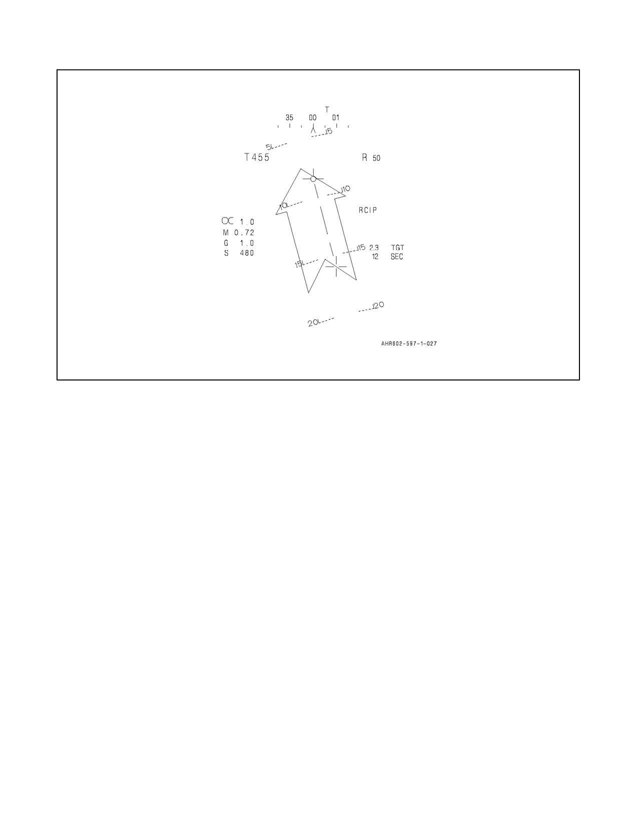
A1-AV8BB--NFM--000
Figure 2-33. GPWS HUD Warning Symbology
2.32.6 Emergency Oxygen
An emergency supply of gaseous oxygen is contained in an emergency oxygen bottle located in the survival kit.
During emergency operation, emergency oxygen is routed through thepilot’s breathing regulator to the pilot’s mask.
2.32.6.1 Emergency Oxygen Actuator
The emergency oxygen actuator can be actuated by pulling up the green ring on the inboard side of the left thigh
support.
2.32.6.1.1 Emergency Oxygen Supply Gauge
Thepressuregaugeis mounted on thepressurereducing and shutoffvalve on the top of theemergency oxygen bottle.
The gauge has a red refill sector from 0 to 1,800 psi and black full sector from 1,800 to 2,500 psi.
2.33
BUILT--IN--TEST
The built--in--test (BIT) mechanization provided within each avionics subsystem forms the basis for fault isolation.
This provides both the pilot and maintenance personnel with the status of the avionics subsystems. The BIT system
provides the pilot with simple displays of system status without interfering with other essential functions. The
mission computer (MC) displays the subsystem BIT results on the DDI and BIT messages delineate the system
failure/anomaly. Two types of BIT are mechanized, periodic and initiated. Periodic BIT begins functioning upon
equipment power application. It provides a failure detection capability that is somewhat less than that provided by
initiated BIT in that it does not interfere with normal equipment operation. Two forms of BIT derived data are
supplied totheMC.Oneformis validityinformation associatedwith selecteddata. Thesecond formis theequipment
failure information which identifies failed weapon replaceable assembly (WRA). The MC uses these two forms of
BIT data to implement reversion operation and advisories for the pilot, as well as equipment status displays for both
the pilot and maintenance personnel.
ORIGINAL
2-116
A1-AV8BB--NFM--000
2.33.1 Reversion
When the BIT equipment determines, through either periodic or initiated BIT, that a function has exceeded a
predetermined threshold, the data derived from that function is immediately indicated as not valid. The MC, upon
receiving this indication, reverts to the next best available source or to a backup mode of operation. This reversion
is maintained as long as the data remains invalid from the primary source. Automatic tactical reversion mechanized
for flight aids, navigation, air--to--air and air--to--ground weapons delivery are shown in Figure 2-34. When a reversion
from a primary path occurs, the pilot is provided with the appropriate cuing on the HUD and DDI only if the reversion
results in some loss of capability or performance. If no reversion path exists, displayed data is removed.
2.33.2 BIT Display
A MENU selectable BIT display (Figure 2-35) contains the status of all avionics equipment which interface with the
MC. During BIT display, messages are displayed next to each affected equipment legend on the DDI. No indication
(blank) adjacent to equipment legend indicates periodic BIT has detected no faults. Messages displayed as a function
of equipment status are listed as follows:
1.
OFF indicates no multiplex response and no equipment ready signal (equipment not turned on, equipment not
present, power supply failure, etc., and for RWR it could also mean avionics mux failure between the digital
data computer and RWR computer).
2.
Asterisk(*) indicates a single mux bus failure on the ground or double mux bus failure during flight.
3.
WRA fail numeral 1 through 16 indicating which WRA within an equipment group is failed.
4.
TEST indicates initiated BIT is commanded but not completed for the equipment (during AUTO BIT, TEST
next to stores management system (SMS) indicates failures are removed from mission computer because the
SMS does not perform an initiated BIT). When there are SMS failure codes, a post--flight IBIT should not be
performed or SMS failures will be cleared from the MC. Inspect failures through the MAINT mode. With H4.0,
SMS will no longer be a part of the AUTO BIT.
5.
DSEL is unique to the GPS indicating the equipment has been deselected. If GPS is deselected during flight
the BIT page will indicate GPS DSEL, until the next power up.
6.
M is unique to the DSS indicating the DSS memory is full.
7.
D is unique to the DSS indicating the DSS has failed check sums.
8.
0 indicates a software compatibility problem and is unique to the SAAHS and ADC BITs. There are two
instances in which a 0 would be considered normal. One instance is the transfer of the MC between any two
of the following platforms: Radar, Night Attack, and Trainer Aircraft without a reload. The other instance
would be a fresh MC load in a Night Attack or Trainer Aircraft. When either of these two instances occurs,
0 may be displayed, but the altitude box does not flash. If this is the case, an Auto BIT should be performed.
If 0 clears, the mission can be continued. If 0 never clears or is not the result of these instances, the mission
should be aborted. A 0 also causes the Altitude Box Symbol to flash on the HUD, this should never be
considered normal.
The following applies with H4.0.
9. NOT LOADED is displayed next to ALMANAC if the miniaturized airborne gps receiver (MAGR) does not
have the GPS Almanac loaded. It is also displayed next to CRYPTO if the MAGR does not have crypto loaded.
10. LOADED is displayed next to ALMANAC if the GPS almanac is loaded into the MAGR. It is also displayed
next to CRYPTO if the MAGR has crypto keys loaded but has not locked onto a GPS signal yet.
11. INCORRECT is displayed next to CRYPTO if the MAGR determines that the loaded crypto keys are incorrect.
12. OK is displayed next to CRYPTO if the MAGR determines that the loaded crypto keys are correct.
2-117
ORIGINAL
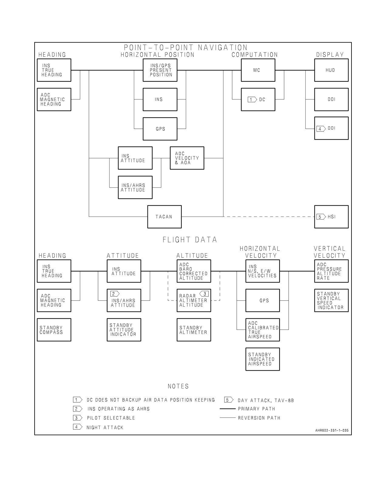
A1-AV8BB--NFM--000
Figure 2-34. Reversions
ORIGINAL
2-118
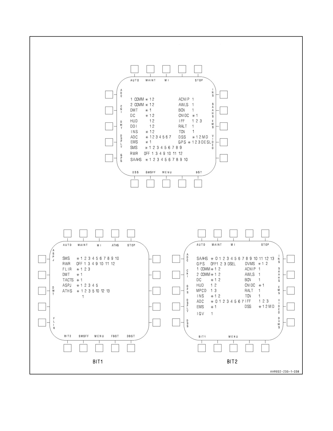
A1-AV8BB--NFM--000
TAV-8B WITH OMNI 7.1 AND
DAY ATTACK AIRCRAFT
NIGHT ATTACK AIRCRAFT WITH C1+
CMDS
Figure 2-35. BIT Displays (Sheet 1 of 4)
2-119
ORIGINAL
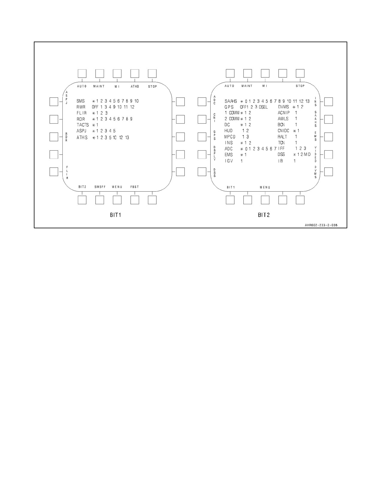
A1-AV8BB--NFM--000
RADAR AIRCRAFT WITH C1+
Figure 2-35. BIT Displays (Sheet 2)
The following applies to H4.0 with tactical aircraft moving map capability (TAMMAC) installed only.
13. OPEN is unique to the Advanced Memory Unit (AMU) indicating the AMU door is open.
14. MAP is unique to the AMU indicating that a MAP formatted card is installed.
15. F1 is unique to the AMU indicating mandatory files are missing from the installed mission card.
16. F2 is unique to the AMU indicating mandatory files are missing from the installed maintenance card.
17. D1 is unique to the AMU indicating the mission card has failed checksums.
18. D2 is unique to the AMU indicating the maintenance card has failed checksums.
19. M1 is unique to the AMU indicating the mission card memory is full.
20. M2 is unique to the AMU indicating the maintenance card memory is full.
21. U is unique to the AMU indicating the Fatigue Tracking User Program is present on the maintenance card but
the program is not running in the AMU.
Note
If U is displayed the operator should initiate an AMU BIT. If the U persists,
the maintenance card should be reloaded on an AMS system.
Pressing the MENU, then the BIT pushbutton on the DDI selects the BIT display which displays the appropriate
message next to the affected equipment. For the SAAHS, of the 17 possible WRA failures only 10 can be displayed
at a time on TAV--8B (with ONMI 7.1) and Day Attack aircraft or 14 on Radar and Night Attack aircraft. If more
failures are reported than can be displayed only the first 10/14 are displayed (any combination totaling not more than
33 spaces).
ORIGINAL
2-120
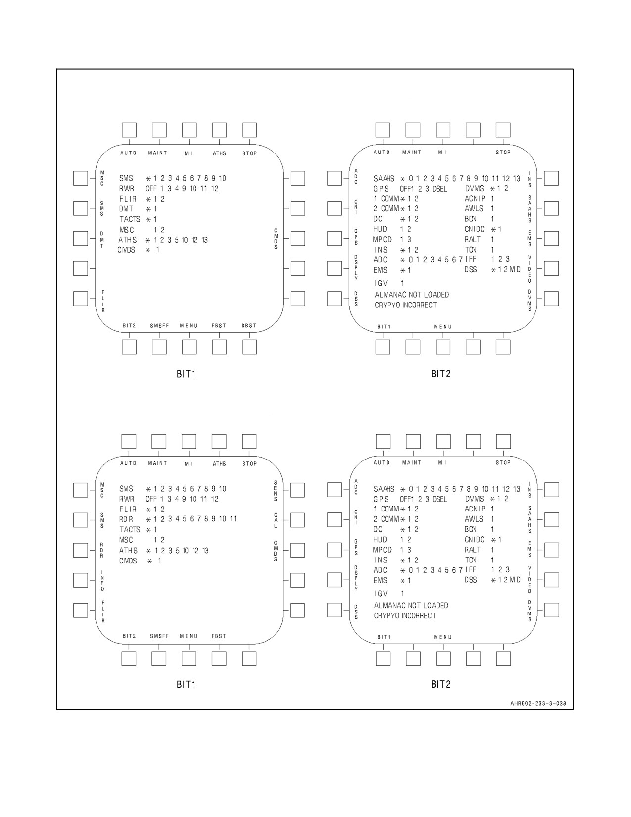
A1-AV8BB--NFM--000
TAV-8B AND NIGHT ATTACK AIRCRAFT WITH
H4.0 AND TAMMAC NOT INSTALLED
RADAR AIRCRAFT WITH H4.0
AND TAMMAC NOT INSTALLED
IB
1
Figure 2-35. BIT Displays (Sheet 3)
2-121
ORIGINAL
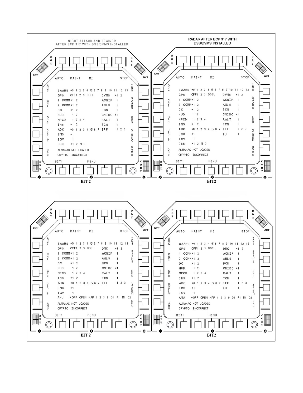
A1-AV8BB--NFM--000
TAV-8B AND NIGHT ATTACK AIRCRAFT
RADAR AIRCRAFT WITH H4.0 AND TAMMAC
WITH H4.0 AND TAMMAC INSTALLED
INSTALLED
Figure 2-35. BIT Displays (Sheet 4)
ORIGINAL
2-122
A1-AV8BB--NFM--000
Figure 2-36 contains a listing of WRA failure numerals with the associated equipment display nomenclature. In
addition, a brief description of system/aircraft degradation is given for each failed WRA.
All WRA failures which are present when the BIT display is selected or were present for 2 minutes before selection
of the BIT display and all MUX bus failures are displayed on the DDI. Limited duration, non--repeatable WRA
failures which were not present for 2 minutes are not stored in the mission computer.
WRA and mux bus failures are reset (removed from mission computer storage) by performing an AUTO BIT (ground
only) or an initiated BIT (IBIT) on the affected equipment. An exception to this is the SAAHS. The flight control
computer stores SAAHS failures and the mission computer displays their status when the BIT display is selected.
These failures can be reset only by performing IBIT or by placing the AFC switch to RESET. All SMS failures are
cleared from the mission computer by an AUTO or initiated BIT. With H4.0, SMS will no longer be a part of the
AUTO BIT. Failures which are detected by periodic BIT will be displayed again as they are detected; however, failed
systemswhicharetestedonlyonstart--upwillhaveallfailureindicationsclearedandwillnotbere--testedbyperiodic,
initiated, or AUTO BIT. MSC IBIT can be commanded in aircraft with H4.0. Once an MSC BIT is commanded, the
MSC goes offline. Since the MSC is offline, an MSC IBIT cannot be stopped unless power to the MSC is secured.
Backup displays produced by the display computer are displayed if the display computer is functioning correctly.
2.33.3 BIT Reporting
During postflight it is the pilot’s responsibility to record (before engine shutdown) and report to ground maintenance
BIT and AUTO BIT equipment fail indications. This reporting can avoid loss of inflight failure indications and the
need for ground maintenance to apply electrical power to obtain BIT and AUTO BIT fail indications. The velocity
reasonableness BIT failures (ADC 7, INS 2, and GPS 3) are never displayed on the deck even if the failures lasted
more than 2 minutes. They are designed to provide the pilot with additional situational awareness while inflight.
2.33.4 BIT Initiation
In addition to displaying equipment BIT status, the DDI is used to command initiated BIT. Those avionics sets
identified by thelegends on the BIT display periphery have an initiated BIT capability. Thepilot commands initiated
BIT by pressing the adjacent button. The status messages are displayed as required as each equipment set enters,
performs, and completes its BIT routine.
During the AMU BIT, the AMU pauses the Fatigue Tracking User Program. After the AMU completes BIT, the MSC
willwait15secondstoverifythattheFatigueTrackingUserProgramhas restarted.Iftheuserprogramis notrunning,
the MSC will automatically command another BIT (up to 6 times total). Therefore, the AMU BIT process may vary
in length (anywhere from 18 to 108 seconds). If the user program fails to start 15 seconds after the last AMU BIT,
U will be displayed next to the AMU legend on BIT page 2.
To perform a simultaneous initiated BIT on all systems except INS, RWR, SAAHS, SMS, and MSC (H4.0 only),
the AUTO button is pressed. When the AUTO button is pressed, all failure codes are cleared for all systems. The INS,
RWR and SAAHS failure codes may appear as each system performs its periodic BIT. SMS will display TEST for
approximately 45 seconds, allowing the SMS time to report the results of its periodic BIT. With H4.0, SMS will no
longer be a part of the AUTO BIT.
Note
D The SAAHS has 17 WRA failure codes. However, only 10 can be displayed
at any given time on TAV--8B (with OMNI 7.1) and Day Attack aircraft or
14 on Trainer (with H4.0), Radar, and Night Attack aircraft (* and 0--13 or
any combination totaling not more than 33 spaces). If more than 14 WRAs
are reported, only the first 14 (or 33 spaces total) will be displayed.
D When TAMMAC is installed, the AMU has 19 different WRA failure
codes. There is a maximum of 33 spaces available for display of failures
on the AMU line. If more than 33 spaces worth of failures are being
reported, only the first 33 spaces will be displayed.
2-123
ORIGINAL

A1-AV8BB--NFM--000
FAILURE NUMERAL
EQUIPMENT
INDICATION TO PILOT
(WRA)
ACNIP
1
ACNIP WRA failure
0
Software compatibility problem
1
Invalid air data parameter(s) removed from HUD
2
AOA removed from HUD
3
TAS not available for display on HUD when A/G selected
ADC
4
Altitude removed from HUD
5
Magnetic heading invalid
6
Magnetic heading invalid
7
Velocity Reasonableness Test Failure
OPEN
The AMU door is open
MAP
A MAP formatted card is installed
1
AMU WRA failure
2
High Speed Interface Bus (HSIB) failure
3
Mission Card failure
4
Mission Card format improper
5
Mission Card type improper
6
Maintenance Card failure
7
Maintenance Card format improper
9
AMU
8
Maintenance Card type improper
9
AMU and PC Card Ambiguity
D1
Mission Card Failed Checksum
F1
Required mission files are missing
M1
Mission Card memory is full
D2
Maintenance Card failed checksum
F2
Required maintenance files are missing
M2
Maintenance Card memory is full
U
Fatigue Tracking User program is not running but present
1
Low band receiver failure
2
High band receiver failure
1
ASPJ
3
Processor failure
4
Low band transmitter failure
5
High band transmitter failure
1
A1, Interface Assembly
2
A2, Switch Assembly
3
A3, Modem, A Assembly
4
Reserved for Modem B Assembly
7
ATHS
5
A5, Modem C Assembly
6
Reserved for Modem D Assembly
10
A10, 1553 and Processor Assembly
12
A12, 1553 I/O Assembly
13
A13, Power Supply and Discrete Assembly
AWLS
1
AWLS receiver failure
BCN
1
Radar beacon R/T failure
CMDS
1
CMDS WRA failure
CNIDC
1
CNI data converter failure
COMM
1
1
Radio 1 failure
2
Radio 1 antenna system failure
COMM
2
1
Radio 2 failure
2
Radio 2 antenna system failure
Figure 2-36.
BIT Failure Indications (Sheet 1 of 3)
ORIGINAL
2-124
A1-AV8BB--NFM--000
FAILURE NUMERAL
INDICATION TO PILOT
EQUIPMENT
(WRA)
1
DC 1 failure
DC
2
DC 2 failure
1
DDI failure (fwd cockpit)
2
DDI
2
DDI failure (aft cockpit)
1
DMC
1
Digital map computer failure
8
2
High speed interface bus (HSIB) failure
9
3
DMT
1
DMT inoperable
1
Data storage set failed
2
Incorrect DSU load
10
DSS
M
DSS memory is full
D
DSU failed checksum
1
DVMS
1
Digital map computer failure
10
2
Digital memory unit failure
EMS
1
Engine monitoring unit failure
1
FLIR electronics unit failure
1
FLIR
2
FLIR sensor failure
4
3
FLIR power supply failure
1
GPS receiver fail
2
GPS battery fail
5
GPS
3
Velocity reasonableness test failure
8
4
GPS antenna fail
1
Cockpit HUD failure
HUD
2
Aft cockpit HUD failure
4
IB
1
Interference blanker failure
6
IGV
1
Inlet Guide Failure
1
IFF R/T failure
IFF
2
KIT--1A failure
3
IFF antenna system failure
1
Automatic reversion to AHRS mode
INS
2
Velocity reasonableness test failure
1
Left MPCD failure (fwd cockpit)
1
MPCD
3
Right MPCD failure (fwd cockpit)
RALT
1
Radar altimeter R/T failure
1
Radar target data processor
2
Transmitter
3
Receiver/Exciter
4
Computer power supply
5
Antenna
6
Antenna electronics
4
RDR
7
Transmitter flow low (indicates low liquid coolant)
8
Waveguide pressure low
9
Weight--on--wheels/inflight disagree
8
10
Radar hardware or aircraft launch discrete to Radar not
AMRAAM compatible
8
11
AMRAAM data link RF power test fail
8
12
System failure detected, run I--BIT to isolate fault
Figure
2-36.
BIT Failure Indications (Sheet 2)
2-125
ORIGINAL
A1-AV8BB--NFM--000
FAILURE NUMERAL
INDICATION TO PILOT
EQUIPMENT
(WRA)
1
RWR computer inoperable
3
Special receiver inoperable
4
Integrated antenna array inoperable
RWR
9
Quadrant receiver at 315° inoperable
10
Quadrant receiver at 225° inoperable
11
Quadrant receiver at 135° inoperable
12
Quadrant receiver at 45° inoperable
0
Software compatibility problem
1
Invalid mode or function inoperable
2
Loss of pitch or roll or yaw function
3
Loss of coordinated turn function
4
Loss of control stick steering or emergency disengage
5
Loss of forward pitch stab aug in approach
6
Loss of pitch stab aug
7
Loss of forward pitch stab aug in approach
8
Loss of roll stab aug
SAAHS
9
Loss of roll stab aug
10
Loss of rudder trim and yaw stab aug
11
Loss of roll/yaw interconnect
12
Loss of particular switch function, or SAAHS switches off
during BIT
13
Loss of auto pitch trim or manual trim input
14
Loss or auto roll trim or manual trim input
15
Forward lateral accelerometer or roll rate gyro failed
16
Static inverter or contactor failed
1
SMS computer failure
2
Armament control panel failure
3
Station 1 controller failure
4
Station 2 controller failure
5
Station 3 controller failure
SMS
6
Station 4 controller failure
7
Station 5 controller failure
8
Station 6 controller failure
9
Station 7 controller failure
1
10
Aircraft wiring
1
TACTS
1
AISI failure
TCN
1
Tacan R/T failure
NOTES:
1
AV--8B 163853 and up.
2
TAV--8B, AV--8B Day Attack.
3
TAV--8B, AV--8B 161573 through
164547.
4
AV--8B 164549 and up.
5
AV--8B 165384 and up; also AV--8B 161573 through 165383, TAV--8B 162963 through 164542 after
AFC--354 Rev A/Part 2/Part 3.
6
AV--8B 165354 and up.
7
AV--8B 165305 and up; also AV--8B 163853 through 165006 after AFC--326/Part 3.
8
H4.0 only.
9
H4.0 with TAMMAC installed.
10
TAMMAC not installed.
Figure 2-36. BIT Failure Indications (Sheet 3)
ORIGINAL
2-126
A1-AV8BB--NFM--000
During AUTO BIT a mixture of tones is heard in the headset. These tones result from simultaneous BIT checks of
the ACNIP and the two VHF/UHF receiver--transmitters. The ACNIP tone consists of three 2.5 KHz to 3.5 KHz beeps
for approximately 6 seconds, followed for approximately 2 seconds by two cycles of the LAW tone and one cycle
of the hooter tone. Each receiver--transmitter BIT produces a series of 960 Hz on/off tones while BIT is in progress
and a steady 960 Hz tone after BIT completion. The total BIT time for the transmitter--receivers is typically from 3
to 6 seconds. The total time for the mixture of tones heard during the AUTO BIT varies from approximately 3 to 10
seconds. The sound heard will vary in accordance with the volume control settings of the above three pieces of
equipment. AUTO BIT causes the INS and CIP/AUT caution lights to come on for a short period of time. At times
this period will be long enough to trigger the MASTER CAUTION light. This is normal operation.
For subsystems which require operator participation for initiated BIT thoroughness, a maintenance BIT is provided.
The AUTO, ARBS, MSC (H4.0 only) and MAINT BITs are usable only on the ground and must be performed with
the aircraft stationary.
Note
Performing an AUTO BIT during taxi can cause false failure codes.
The STOP button allows the pilot to stop initiated BIT or AUTO BIT at any time. The same effect is also achieved
by pressing MENU. With either method, any test in progress stops and the equipment returns to normal operation.
The COMM 1 and COMM 2 BIT cannot be stopped once initiated, the TEST legend may be removed from the DDI
but tones will be heard as BIT is performed. The GPS test cannot be stopped once initiated. With H4.0, BITs stop
if they complete, or either MAINT or STOP is pressed. BITs continue even if the BIT page is left. With H4.0, if a
system is unable to complete its BIT test, a ? is displayed next to the system’s label. The following legends are not
displayed on the BIT display during flight: MAINT, AUTO, ADC, INS, SAAHS and MSC (H4.0 only).
Systems have to be turned on and warmed up for initiated BIT. Warm up times are: RALT, 3 minutes; AWLS, 15
seconds; IFF, TCN, and beacon (BCN), 30 seconds; and SAAHS has a 2--minute rate gyro run up time. If BIT is
commanded before the system is warmed up the display will indicate TEST until warmup is completed.
Note
If a CNIDC BIT failure occurs, the status of critical IFR flight equipment
(TACAN, RADALT, BCN, IB, IFF, AWLS, and ACNIP) will not be
known.
On AV--8B 164549 and up, an Operational Readiness Test (ORT) is performed on the radar whenever the aircraft is
powered up. The ORT is nearly the same as an initiated BIT, however, it cannot be stopped once started. The ORT
is automatically initiated whenever the radar has been turned off for more than 7 seconds and is powered up. This
interval defines a cold start. When the radar is turned on, it takes 3.5 to 4.0 minutes for warmup and ORT. The ORT
is performed concurrent with the warmup process and begins after 30 seconds.
During ORT and initiated BIT with weight--on--wheels, the radar transmitter is tested with the radiation path into a
dummy load to protect the ground crew from radiation hazard. Transmitter tests take about 30 to 45 seconds to
complete, however the tests are inhibited if STBY or EMCON are selected during warmup. The radar will not
function until the transmitter tests are complete. If the aircraft takes off in EMCON the tests will not be completed
until EMCON is deselected. The pilot has no indication that the radar is not ready.
On AV--8B 161573 through 162973, auxiliary communication, navigation, identification panel (ACNIP) initiated
BIT is also initiated each time the ACNIP mode switch is positioned to MAN. On TAV--8B, AV--8B 163176 and up,
the battery switch must be in the alert mode to enable the ACNIP initiated BIT. A one second warning tone (hooter)
indicates the ACNIP passed BIT. On TAV--8B 163856 and up, AV--8B 163519 and up, ACNIP BIT pass is indicated
by an ACNIP GO, ACNIP GO voice warning and ACNIP BIT fail is indicated by an ACNIP FAIL, ACNIP FAIL
voice warning.
2-127
ORIGINAL
A1-AV8BB--NFM--000
Note
If emission control (EMCON) is selected, initiated BIT for the radar
altimeter and IFF are inhibited, also the radar transmit function on AV--8B
164549 and up.
Initiated BIT procedures are described in the systems coverage throughout this manual where applicable. With a
combined knowledge of reversion operation (Figure 2-34) and WRA failure numerals (Figure 2-36), it is sometimes
possible for the pilot to determine the extent of system/aircraft operational degradation due to avionics equipment
failure/anomaly.
On aircraft afterAFC--392, theEnhanced VariableInlet GuideVane Control System (EVICS)conducts an automatic
BIT check after engine start. The BIT check verifies proper operation of the EVICS, Hydro--Mechanical Unit (HMU)
and T1 temperature sensor. Component failure is indicated by IGV 1 on the BIT 2 Page.
2.34
DDI MISSION COMPUTER OFP DISPLAY (OMNI 7.1 AND C1+)
The ID number of the current operational flight program (OFP) load for the mission computer can be determined by
selecting the maintenance display on the DDI. The maintenance display is selected by the following procedure:
1. Select BIT display from MENU.
2. Select MAINT from BIT display.
With the maintenance display selected, the current mission computer OFP is displayed above the MENU button
legend at the bottom center of the display.
2.35
SOFTWARE CONFIGURATION PAGE (H4.0 ONLY)
The software configurations of certain systems can be viewed by accessing the configuration displays (CONF1 or
CONF2) from the main menu display by pressing CONF. See Figures 2-37 and 2-38. The MSC automatically
performs a configuration check with the peripherals shown on the configuration pages. If a fault such as an incorrect
software load is detected for one of the peripherals during the MSC power up cycle, the appropriate configuration
page with the faulty item shall be displayed on the left MPCD with the offending software load flashing and ACK
in window 1 of theODU. When ACK is selected thesoftware identifierof theoffending item is lined out, as depicted
in Figure 2-37. Items listed on the software configuration pages that are not powered up or are not applicable to that
typeofaircraft, areleft blank. IfTAMMAC is installed in theaircraft, NOT COMPATIBLE may appearflashingnext
to the digital map computer (DMC) legend. This indicates a map theater load or symbol set that is not compatible
with the AV--8B. This can be corrected by loading an AV--8B theater from an AMU MAP card.
Note
Flight with a software configuration fault is prohibited.
2.36
POSTFLIGHT DATA RETRIEVAL
ThemissioncomputerstoresWRAfailuresforpostflightretrieval.Toreportthesefailures,theBITdisplay isselected
before engine shutdown and the failures are recorded for use by maintenance personnel.
ORIGINAL
2-128
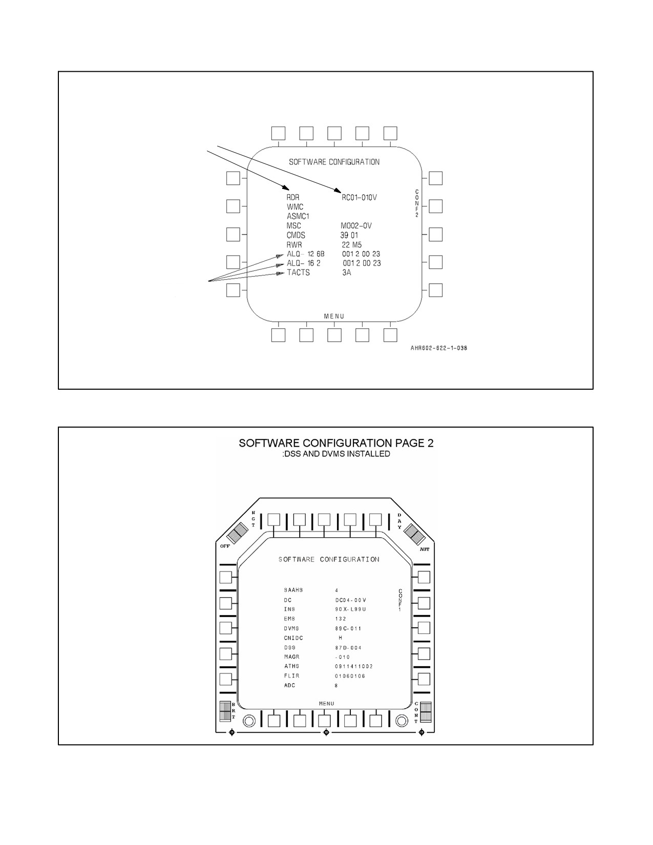
A1-AV8BB--NFM--000
BLANK IF IN NIGHT ATTACK AIRCRAFT
CONFIG FAULT
WX04-0V
74-014
ALQ-126B, ALQ-162,
TACTS, AND TPOD WILL
TPOD
0000 B550
ONLY BE DISPLAYED IF
INSTALLED
Figure 2-37. Configuration Page 1 (Configuration fault detected)
Figure 2-38. Configuration Page 2 (DSS and DVMS Installed) (Sheet 1 of 2)
2-129
ORIGINAL
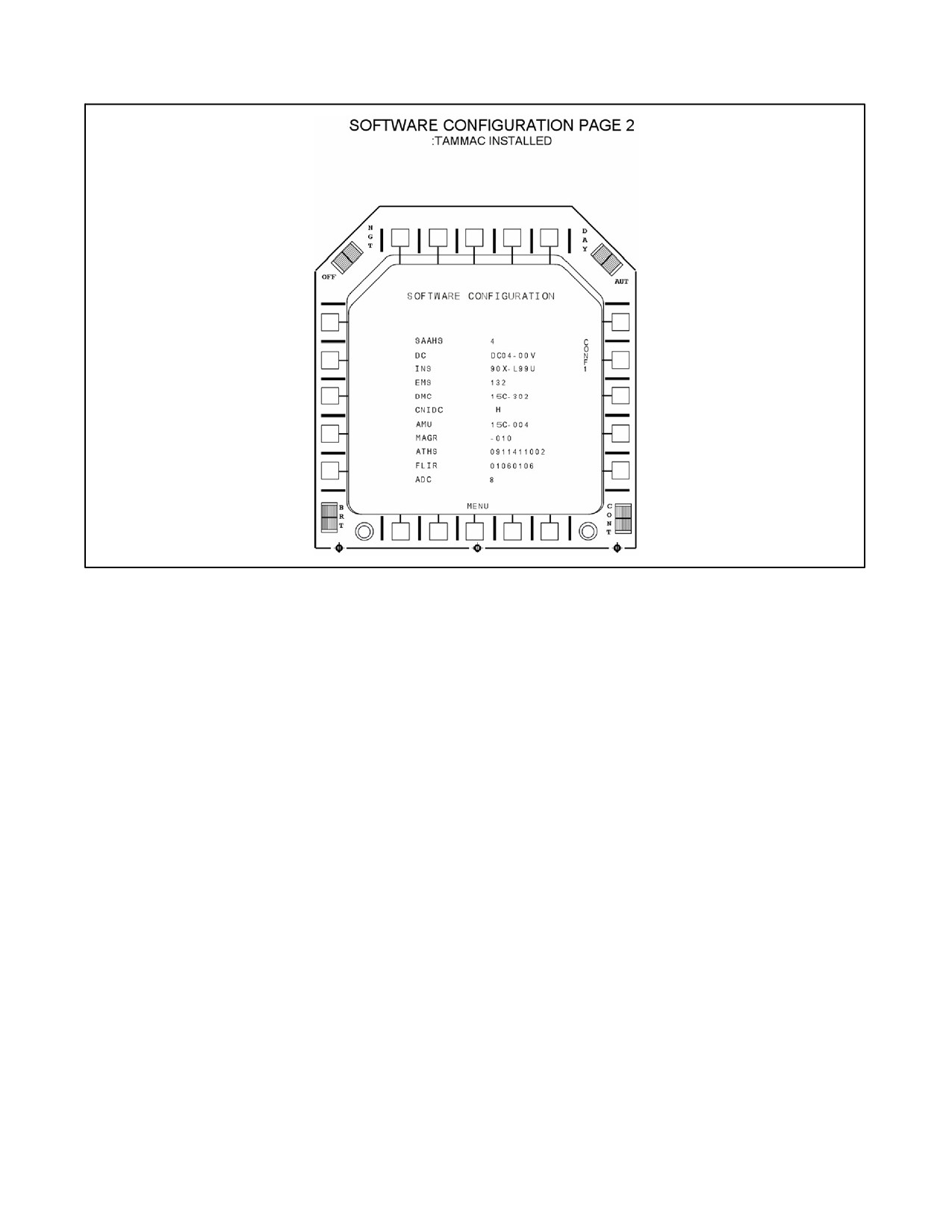
A1-AV8BB--NFM--000
Figure 2-38. Configuration Page 2 (DSS and DVMS Installed) (Sheet 2)
ORIGINAL
2-130
A1-AV8BB--NFM--000
CHAPTER 3
Servicing and Handling
3.1
SERVICING
Refer to A1--AV8BB--NFM--600.
3-1/(3-2 blank)
ORIGINAL