NATOPS FLIGHT MANUAL NAVY MODEL AV--8B/TAV--8B 161573 AND UP AIRCRAFT (2008) - page 1
A1-AV8BB-NFM-000
THE AIRCRAFT
1
INDOCTRINATION
2
NATOPS FLIGHT MANUAL
NORMAL
3
NAVY MODEL
PROCEDURES
AV--8B/TAV--8B
FLIGHT
161573 AND UP
4
CHARACTERISTICS
AIRCRAFT
EMERGENCY
THIS PUBLICATION SUPERSEDES NAVAIR
5
PROCEDURES
A1-AV8BB--NFM--000 DATED 01 SEPTEMBER 2006
AND CHANGE 1 -- 23 APRIL 2007.
THIS PUBLICATION IS INCOMPLETE WITHOUT
ALL-WEATHER
6
A1-AV8BB--NFM--400.
OPERATION
COMMUNICATION
7
PROCEDURES
WEAPONS
8
SYSTEMS
FLIGHT CREW
9
COORDINATION
DISTRIBUTION STATEMENT C — Distribution authorized to U.S. Government
Agencies and their contractors to protect publications required for official use or for
administrative or operational purposes only, 15 March 2008. Other requests for this
document shall be referred to Commander, Naval Air Systems Command
NATOPS
10
(PMA--257), 47123 Buse Rd, Bldg 2272, Patuxent River, MD 20670--1547.
EVALUATION
DESTRUCTION NOTICE — For unclassified, limited documents, destroy by any
method that will prevent disclosure of contents or reconstruction of the document.
PERFORMANCE
11
DATA
ISSUED BY AUTHORITY OF THE CHIEF OF NAVAL OPERATIONS AND
UNDER THE DIRECTION OF THE COMMANDER,
NAVAL AIR SYSTEMS COMMAND.
INDEX & FOLDOUTS
0801LP1082212
1
(Reverse Blank)
15 MARCH 2008
ORIGINAL
A1-AV8BB-NFM-000
DEPARTMENT OF THE NAVY
NAVAL AIR SYSTEMS COMMAND
RADM WILLIAM A. MOFFETT BUILDING
47123 BUSE ROAD, BLDG 2272
PATUXENT RIVER, MD 20670-1547
15 March 2008
LETTER OF PROMULGATION
1. The Naval Air Training and Operating Procedures Standardization (NATOPS) Program is a
positive approach toward improving combat readiness and achieving a substantial reduction in the
aircraft mishap rate. Standardization, based on professional knowledge and experience, provides the
basis for development of an efficient and sound operational procedure. The standardization program
is not planned to stifle individual initiative, but rather to aid the Commanding Officer in increasing
the unit’s combat potential without reducing command prestige or responsibility.
2. This manual standardizes ground and flight procedures but does not include tactical doctrine.
Compliance with the stipulated manual requirements and procedures is mandatory except as
authorized herein. In order to remain effective, NATOPS must be dynamic and stimulate rather than
suppress individual thinking. Since aviation is a continuing, progressive profession, it is both
desirable and necessary that new ideas and new techniques be expeditiously evaluated and
incorporated if proven to be sound. To this end, Commanding Officers of aviation units are
authorized to modify procedures contained herein, in accordance with the waiver provisions
established by OPNAV Instruction 3710.7, for the purpose of assessing new ideas prior to initiating
recommendations for permanent changes. This manual is prepared and kept current by the users in
order to achieve maximum readiness and safety in the most efficient and economical manner. Should
conflict exist between the training and operating procedures found in this manual and those found
in other publications, this manual will govern.
3. Checklists and otherpertinent extracts from this publicationnecessary tonormal operationsand
training should be made and carried for use in naval aircraft.
S. R. EASTBURG
Rear Admiral, United States Navy
By direction of
Commander, Naval Air Systems Command
3/(4 blank)
ORIGINAL
A1-AV8BB-NFM-000
INTERIM CHANGE SUMMARY
The following Interim Changes have been cancelled or previously incorporated into this manual.
INTERIM
CHANGE
NUMBER(S)
REMARKS/PURPOSE
1 thru 33
Previously incorporated
The following Interim Changes have been incorporated into this Change/Revision.
INTERIM
CHANGE
NUMBER(S)
REMARKS/PURPOSE
34
192005Z MAR 07 Crosswind Component Calculation
35
202004Z JUN 07 Landing Gear EP/EAAS
36
102006Z DEC 07 Emergency DC Wiring AFC--481
Interim Changes Outstanding — To be maintained by the custodian of this manual.
INTERIM
CHANGE
ORIGINATOR/DATE
PAGES
NUMBER
(or DATE/TIME GROUP)
AFFECTED
REMARKS/PURPOSE
37
242006Z NOV 08
18--5(18--6
CHP 18 OCF Procedure Correction
Blank)
38
052015Z FEB 09
9--17/18
RendezvousTechnique
5/(6 blank)
ORIGINAL
P 052015Z FEB 09
FM COMNAVAIRSYSCOM PATUXENT RIVER MD//4.0P//
TO ALL HARRIER AIRCRAFT ACTIVITIES
COMNAVAIRFOR SAN DIEGO CA//N421A//
AIRTEVRON THREE ONE CHINA LAKE CA//51J000D/51J00MD//
COMFLOAN MARISTAT INFO COMNAVSAFECEN NORFOLK VA//11//
COMNAVAIRSYSCOM PATUXENT RIVER MD//4.0P/4.1/5.0F/4.6.3.3//
VMAT TWO ZERO THREE//CO/OPSO/NATOPS/MO//
FLTREADCEN EAST CHERRY PT NC//AV8FST//
PEOTACAIR PATUXENT RIVER MD//PMA-257/PMA-257SP/PMA-257IT//
AJEMA//NINTHSQUADRON//
GRUPAER GROTTAGLIE COMMARFORCOM//ALD/G-6/DSS//
COMMAFORPAC//ALD/G-6/DSS//
CG FIRST MAW//ALD/G-6/DSS//
CG SECOND MAW//ALD/G-6/DSS//
CG THIRD MAW//ALD/G-6/DSS//
MAG TWELVE//CO/OPSO/MO/DSS//
MAG THIRTEEN//CO/OPSO/MO/DSS//
MAG FOURTEEN//CO/OPSO/MO/DSS//
VMA 211//CO/OPSO/MO/DSS//
VMA 214//CO/OPSO/MO/DSS//
VMA 223//CO/OPSO/MO/DSS//
VMA 231//CO/OPSO/MO/DSS//
VMA 311//CO/OPSO/MO/DSS//
VMA 513//CO/OPSO/MO/DSS//
VMA 542//CO/OPSO/MO/DSS//
MSGID/GENADMIN,USMTF,2007/COMNAVAIRSYSCOM PATUXENT RIVER//
SUBJ/AV-8B AIRCRAFT NATOPS PUBLICATIONS INTERIM CHANGE//
REF/A/MSGID:EML/COMMARFORCOM/26JAN2009//
REF/B/MSGID:DOC/NAVAIR/09SEP2008//
REF/C/MSGID:DOC/NAVAIR/15MAR2008//
NARR/REF (A) IS COG CONCURRENCE.
REF (B) IS AIRS 2008-165.
REF (C) IS AV-8B A1-AV8BB-NFM-000 NATOPS FLIGHT MANUAL DTD 15 NOV
2008.//
GENTEXT/REMARKS/1. THIS MESSAGE IS ISSUED IN RESPONSE TO REFS (A) AND
(B). THIS MESSAGE ISSUES INTERIM CHANGE (IC) NUMBER 38 TO REF (C).
2. SUMMARY.
A. THIS MESSAGE ISSUES NEW PARA 9.1.7.4, RENDEZVOUS TECHNIQUE,
ADDRESSING USE OF NOZZLES TO CONTROL CLOSURE RATE, TO REF (C).
B. REPLACEMENT PAGES CONTAINING THESE CHANGES FOR DOWNLOADING
AND INSERTION INTO REF (C) WILL BE ATTACHED TO THIS INTERIM
CHANGE MESSAGE WHEN IT IS POSTED ON THE NATEC AND
AIRWORTHINESS WEBSITES (SEE LAST PARA BELOW).
3. THE REPLACEMENT PAGES IMPACT THE FOLLOWING NATOPS FLIGHT MANUAL.
THE REPLACEMENT PAGE PACKAGE INCLUDES THE FOLLOWING PAGES:
A. REF (C) (AV-8B NFM-000) PAGES 5/(6 BLANK), 9-17, 9-18, 9-
18A/(B BLANK).
B. TO ENSURE THE PDF PAGES PRINT TO SCALE: SELECT PRINT AND
VIEWING PRINT SETUP WINDOW, ENSURE "NONE" IS SELECTED IN
THE PAGE SCALING DROPDOWN.
4. POINTS OF CONTACT:
A. AV-8B NATOPS PROGRAM MANAGER:
(1) MAJ JOHN ROUNTREE, VMAT-203, (252) 466-4863 EXT 3151, DSN
582-4863 EXT3151, E-MAIL JOHN.D.ROUNTREE(AT)USMC.MIL.
B. NAVAIR POCS:
(1) MARTY SCANLON, NATOPS IC COORDINATOR, TEL DSN 757-6045
NAVAIR 052015Z FEB 09
Page 1 of 2
A1-AV8BB-NFM-000 IC 38
OR COMM (301) 757-6045, EMAIL: MARTIN.SCANLON(AT)NAVY.MIL
(2) LTCOL JASON MADDOCKS, PMA-257 APMSE, (301) 757-5458, DSN
757-5458, E-MAIL JASON.MADDOCKS(AT)NAVY.MIL
(3) KRISTIN SWIFT, AIR-4.0P, NATOPS CHIEF ENGINEER, (301)
995-4193, DSN 995-4193, E-MAIL KRISTIN.SWIFT(AT)NAVY.MIL.
(4) AIRWORTHINESS GLOBAL CUSTOMER SUPPORT TEAM,
TEL: 301-757-0187, EMAIL: NAVAIR_4.0P_IFC@NAVY.MIL.
5. THIS MESSAGE WILL BE POSTED ON THE NATEC WEBSITE,
MESSAGES MAY BE FOUND IN TWO PLACES ON THIS WEBSITE:
A. IN THE NATOPS IC DATABASE FOUND UNDER THE TMAPS OPTION.
B. IN THE AFFECTED PUBLICATIONS(S) JUST AFTER THE IC SUMMARY PAGE.
IF THE IC MESSAGE INCLUDES REPLACEMENT PAGES, THEY WILL BE ADDITIONALLY
PLACED WITHIN THE MANUAL AND REPLACED PAGES DELETED.
MESSAGES ARE NORMALLY POSTED IN THE DATABASE BEFORE APPEARING IN THE
PUBLICATION. THIS MESSAGE WILL ALSO BE POSTED ON THE AIRWORTHINESS
WEBSITE, AIRWORTHINESS.NAVAIR.NAVY.MIL. IF UNABLE TO VIEW THIS MESSAGE
ON EITHER THE NATEC OR AIRWORTHINESS WEBSITES, INFORM THE NATOPS GLOBAL
CUSTOMER SUPPORT TEAM AT (301) 342-3276, DSN 342-3276, OR BY EMAIL AT
NATOPS(AT)NAVY.MIL.
C. INFORMATION REGARDING THE AIRWORTHINESS PROCESS, INCLUDING A
LISTING OF ALL CURRENT INTERIM FLIGHT CLEARANCES, NATOPS AND NATIP
PRODUCTS ISSUED BY NAVAIR 4.0P, CAN BE FOUND AT OUR WEBSITE:
AIRWORTHINESS.NAVAIR.NAVY.MIL.
D. E-POWER FOLDER 851943, TRACKING NUMBER 33118.//
Kristin Swift, NATOPS Chief Engineer, 4.0P, 02/05/2009
NAVAIR 052015Z FEB 09
Page 2 of 2
A1-AV8BB-NFM-000 IC 38
P 242006Z NOV 08
FM COMNAVAIRSYSCOM PATUXENT RIVER MD//4.0P//
TO ALL HARRIER AIRCRAFT ACTIVITIES
COMNAVAIRFOR SAN DIEGO CA//N421A//
AIRTEVRON THREE ONE CHINA LAKE CA//51J000D/51J00MD//
COMFLOAN MARISTAT
INFO COMNAVSAFECEN NORFOLK VA//11//
COMNAVAIRSYSCOM PATUXENT RIVER MD//4.0P/4.1/5.0F/4.6.3.3//
VMAT TWO ZERO THREE//CO/OPSO/NATOPS/MO//
FLTREADCEN EAST CHERRY PT NC//AV8FST//
PEOTACAIR PATUXENT RIVER MD//PMA-257/PMA-257SP/PMA-257IT//
AJEMA//NINTHSQUADRON//
GRUPAER GROTTAGLIE COMMARFORCOM//ALD/G-6/DSS//
COMMAFORPAC//ALD/G-6/DSS//
CG FIRST MAW//ALD/G-6/DSS//
CG SECOND MAW//ALD/G-6/DSS//
CG THIRD MAW//ALD/G-6/DSS//
MAG TWELVE//CO/OPSO/MO/DSS//
MAG THIRTEEN//CO/OPSO/MO/DSS//
MAG FOURTEEN//CO/OPSO/MO/DSS//
VMA 211//CO/OPSO/MO/DSS//
VMA 214//CO/OPSO/MO/DSS//
VMA 223//CO/OPSO/MO/DSS//
VMA 231//CO/OPSO/MO/DSS//
VMA 311//CO/OPSO/MO/DSS//
VMA 513//CO/OPSO/MO/DSS//
VMA 542//CO/OPSO/MO/DSS//
MSGID/GENADMIN,USMTF,2007/COMNAVAIRSYSCOM/4.0P//
SUBJ/AV-8B AIRCRAFT PRELIMINARY NATOPS PUBLICATIONS INTERIM CHANGE
/SAFETY OF FLIGHT//
REF/A/MSGID:EML/COMMARFORCOM/20NOV2008//
REF/B/MSGID:DOC/NAVAIR/19NOV2008//
REF/C/MSGID:DOC/NAVAIR/15MAR2008//
NARR/REF (A) IS COG CONCURRENCE.
REF (B) IS AIRS 2008-228.
REF (C) IS AV-8B A1-AV8BB-NFM-000 NATOPS FLIGHT MANUAL DTD 15 NOV
2008.//
GENTEXT/REMARKS/1. THIS MESSAGE IS ISSUED IN RESPONSE TO REFS (A) AND
(B). THIS MESSAGE ISSUES INTERIM CHANGE (IC) NUMBER 37 TO REF (C).
2. SUMMARY.
A. THIS MESSAGE ISSUES AND ADMIN CORRECTION TO PAGE 18-5, PARA
18-20-2, IMMEDIATE ACTION ITEMS FOR OUT OF CONTROL FLIGHT/
SPIN/FALLING LEAF RECOVERY PROCEDURES.
B. REPLACEMENT PAGES CONTAINING THESE CHANGES FOR DOWNLOADING
AND INSERTION INTO REF (C) WILL BE ATTACHED TO THIS INTERIM
CHANGE MESSAGE WHEN IT IS POSTED ON THE NATEC AND
AIRWORTHINESS WEBSITES (SEE LAST PARA BELOW).
3. THE REPLACEMENT PAGES IMPACT THE FOLLOWING NATOPS FLIGHT MANUAL.
THE REPLACEMENT PAGE PACKAGE INCLUDES THE FOLLOWING PAGES:
A. REF (C) (AV-8B NFM-000) PAGES 5/(6 BLANK) AND 18-5/(18-6
BLANK).
B. TO ENSURE THE PDF PAGES PRINT TO SCALE: SELECT PRINT AND
VIEWING PRINT SETUP WINDOW, ENSURE "NONE" IS SELECTED IN
THE PAGE SCALING DROPDOWN.
4. POINTS OF CONTACT:
A. AV-8B NATOPS PROGRAM MANAGER:
(1) MAJ MICHAEL HUNTING, VMAT-203, (252) 466-2638, DSN
NAVAIR 242006Z NOV 08
Page 1 of 2
A1-AV8BB-NFM-000 IC 37
582-2638, E-MAIL MICHAEL.HUNTING(AT)USMC.MIL
B. NAVAIR POCS:
(1) MARTY SCANLON, NATOPS IC COORDINATOR, TEL DSN 757-6045
OR COMM (301) 757-6045, EMAIL: MARTIN.SCANLON(AT)NAVY.MIL
(2) LTCOL JASON MADDOCKS, PMA-257 APMSE, (301) 757-5458, DSN
757-5458, E-MAIL JASON.MADDOCKS(AT)NAVY.MIL
(3) KRISTIN SWIFT, AIR-4.0P, NATOPS CHIEF ENGINEER, (301)
995-4193, DSN 995-4193, E-MAIL KRISTIN.SWIFT(AT)NAVY.MIL.
(4) AIRWORTHINESS GLOBAL CUSTOMER SUPPORT TEAM,
TEL: 301-757-0187, EMAIL: NAVAIR_4.0P_IFC@NAVY.MIL.
5. THIS MESSAGE WILL BE POSTED ON THE NATEC WEBSITE, WWW. NATEC.MIL
WITHIN 48 HOURS OF RELEASE. NEW NATOPS IC MESSAGES MAY BE FOUND IN TWO
PLACES ON THIS WEBSITE:
A. IN THE NATOPS IC DATABASE FOUND UNDER THE TMAPS OPTION.
B. IN THE AFFECTED PUBLICATIONS(S) JUST AFTER THE IC SUMMARY PAGE.
IF THE IC MESSAGE INCLUDES REPLACEMENT PAGES, THEY WILL BE ADDITIONALLY
PLACED WITHIN THE MANUAL AND REPLACED PAGES DELETED.
MESSAGES ARE NORMALLY POSTED IN THE DATABASE BEFORE APPEARING IN THE
PUBLICATION. THIS MESSAGE WILL ALSO BE POSTED ON THE NATOPS WEBSITE,
AIRWORTHINESS.NAVAIR.NAVY.MIL. IF UNABLE TO VIEW THIS MESSAGE ON EITHER
THE NATEC OR AIRWORTHINESS WEBSITES, INFORM THE NATOPS GLOBAL CUSTOMER
SUPPORT TEAM AT (301) 342-3276, DSN 342-3276, OR BY EMAIL AT
NATOPS(AT)NAVY.MIL.
C. INFORMATION REGARDING THE AIRWORTHINESS PROCESS, INCLUDING A
LISTING OF ALL CURRENT INTERIM FLIGHT CLEARANCES, NATOPS AND NATIP
PRODUCTS ISSUED BY NAVAIR 4.0P, CAN BE FOUND AT OUR WEBSITE:
AIRWORTHINESS.NAVAIR.NAVY.MIL.
D. EPOWER FOLDER NUMBER 848143, TRACKING NUMBER 32809.//
Kristin Swift, NATOPS Chief Engineer, 4.0P, 11/24/2008
NAVAIR 242006Z NOV 08
Page 2 of 2
A1-AV8BB-NFM-000 IC 37
A1-AV8BB-NFM-000
Summary of Applicable Technical Directives
Information relating to the following technical directives has been incorporated into this manual.
Change
ECP
Number
Number
Description
Visual Identification
Effectivity
ASC--020
0102
Improves high speed roll rate
None
AV--8B
(P)162942 and
up
(R)161573
thru 162746
AYC--836
Lucus--08
Mk 4 GTS/APU operational
None
No aircraft
performance enhancement
effectivity
AFC--286
141
Throttle grip modification
None
AV--8B
AYC--873
(P)163659 and
up
(R)161573
thru 163519
AFC--287
85R1
Dual airspeed/altitude sensor
None
AV--8B
arming incorp & removal of
(P)163659 and
external initiated canopy
up
fracturing system arming
(R)161573
thru 163519
—
145
Voice warning
None
AV--8B
(P)163519 and
up
TAV--8B
(P)163856 and
up
—
177
Landing gear blow down bottle
Identification plate installed on
AV--8B
gas change
bottle
(P)163659 and
up
TAV--8B
(P)163856 and
up
—
162
Provisions for incorporation of
15 sec caution light threshold for
TAV--8B
Part 1
F402--RR--408 engine
short lift dry is 684 5º vice
(P)164113 and
687 5º
up
AFC--253
075R1C2
Modification of data storage unit
Mount swings forward for removal
AV--8B
installation
and installation of DSU
(P)163677 and
up
(R)163176
thru 163676
7
ORIGINAL
A1-AV8BB-NFM-000
Change
ECP
Number
Number
Description
Visual Identification
Effectivity
AFC--328
217
Incorporation of two batteries for
Emergency battery/switch on left
AV--8B
emergency backup power
canopy sill and on left console
(R)161573
thru 164150
TAV--8B
(R)162747
thru 164542
AFC--332
231
Redundant DECS enable switch
Switch aft left console above
AV--8B
fuel shutoff handle
(P) 164139
and up
(R)161573
thru 164135
TAV--8B
(P)164540 and
up
(R)162747
thru 164138
—
162C3
Add F402--RR--408 engine
ENG ID --408 -- Identification
AV--8B
displayed on ENG display
(P)164116 and
up
ASC--043
DO 30
Incorporates OMNIBUS VII
MC OFP 91--D0FE040K
AV--8B
mission computer OFP
(R)161573
thru 163852
TAV--8B
(R)162747
thru 164542
—
129C/C3
Adds new head up display
Wider field of view HUD
AV--8B
(P)163853 and
up
—
170C1
Power distribution redesign
Changes in circuit breaker panels
AV--8B
(P)163853 and
up
—
161C1/C2
Adds 100% LERX provisions
Forward ram air intakes moved
AV--8B
(P)163853 and
up
—
134C1/
Production night attack
Additional MPCD, night vision
AV--8B
C3/C4
installation
compatible main instrument panel
(P)163853 and
up
—
143C1C2
Stores management system
None
AV--8B
enhancement
(P)163853 and
up
—
161
Adds upward firing dispensing
Four additional dispensers near
AV--8B
system
top of rear fuselage
(P)163853 and
up
ORIGINAL
8
A1-AV8BB-NFM-000
Change
ECP
Number
Number
Description
Visual Identification
Effectivity
ASC--053
226
Incorporates OMNIBUS VI+
MC OFP 90--N0FE030P
AV--8B
mission computer OFP
(P)163853 and
up
—
199C1
Night attack enhancements
An IR source on the HUD video
AV--8B
camera
(P)163853 and
up
—
200R1
Production incorporation of AN/
Radar switch on miscellaneous
AV--8B
APG--65 radar and wiring
switch panel
(P)164549 and
provisions for smart weapons
up
AFC--326
180R1
Incorporation of provisions for
Addition of circuit breaker
AV--8B
ATHS
(R)164548
thru 165006
AFC--326
180R1
Incorporation of provisions for
Addition of circuit breaker
AV--8B
PART 3
ATHS
(R)163853
thru 164547
180R2
Production incorporation of the
Addition of circuit breaker
AV--8B
ATHS
(P)165384 and
up
AFC--354
168C1
Incorporation of GPS provisions
Addition of circuit breaker
AV--8B
REV A
and mini tacan
(R)163853
thru 164547
TAV--8B
(R)164113
thru 164542
AFC--354
168C1
Incorporation of GPS provisions
Addition of circuit breaker
AV--8B
PART 2
and mini tacan
(R)161573
thru 163852
TAV--8B
(R)162963
thru 163861
AFC--354
168C1
Incorporation of GPS provisions
Addition of circuit breaker
AV--8B
PART 3
and mini tacan
(R)164549
thru 165383
168C1R1
Production incorporation of GPS
Addition of circuit breaker
AV--8B
provisions and mini tacan
(P)165384 and
up
161C3
Production incorporation of 100%
100% LERX installed
AV--8B
LERX
(P)163853
thru 164121
200C2
Radar remanufacture for AV--8B
Same as radar aircraft
AV--8B
(P)165305 and
up
9
ORIGINAL
A1-AV8BB-NFM-000
Change
ECP
Number
Number
Description
Visual Identification
Effectivity
AFC--368
RAMEC--
Radar altimeter power distribution
Changes in circuit breaker panels
AV--8B
13--91
(P)164549 and
up
AV--8B
(R)163853
thru 164547
TAV--8B
(R)164113
thru 164542
AFC--370
19R1
MIL--W--81381 wiring
Addition of circuit breakers
AV--8B
replacement
(R)161573
thru 163852
TAV--8B
(R)162747
thru 163861
AFC--391
251R1
Production incorporation of Pilot
Addition of NWS light on caution/
AV--8B
Selectable Hi/Lo Gain Nose
advisory panel
(P)165354 and
Wheel Steering (NWS)
up
AFC--392
254
Incorporation of provisions for
None
AV--8B
IGVC Digital Electronic Control
(P)165354 and
(IDEC)
up
(R)161573
thru 165312
TAV--8B
(R)162747
thru 164542
AFC--394
256
Jet Pipe Temperature
None
AV--8B
modification
(P)165354 and
up
(R)161396
thru 165312
TAV--8B
(R)162747
thru 164542
ASC--76
NWC--
Incorporates Omnibus 7.1
MC OFP
96--D0FE060C
AV--8B
RJW--
(R) 161573
014D--
thru 163852
5310
TAV--8B
(R)162747
thru 164542
ORIGINAL
10
A1-AV8BB-NFM-000
Change
ECP
Number
Number
Description
Visual Identification
Effectivity
AFC--395
257
Uninterupted power to DECU
Addition of circuit breakers
AV--8B
(P)165354 and
up
(R)163853
thru 165312
TAV--8B
(R)164113
thru 164542
ASC--78
JSSA--01
Incorporates Omnibus C1
MC OFP 96--C0FE060L
AV--8B
(P)163853 and
up
AFC--393
255R1
Incorporates DFC and FCEM
DFC OFP 75A870731--
AV--8B
(P)165391
and up
(R)161397
thru 165390
TAV--8B
(R)164113
thru 164542
AFC--409
JSSA--01
Incorporates ARC--210 Radio
New Radio Set Control Panel
AV--8B
(P)165384
and up
(R) 163853
thru 165383
AFC--420
270R1
Incorporates MIL--STD--1760
Added Circuit Breakers
AV--8B
Wiring
(P)165413
and up
(R) 163853
thru 165412
AFC--422
CHPT--
Incorporates
8mm Video
8mm Video Recorder
AV--8B
029
Recorder
(P) 165422
and up
(R) 161573
thru 165421
TAV--8B
(R)162747
thru 164542
AFC--373
246
Incorporation of Pyrotechnic
Addition of SMDC thruster on
TAV--8B
Canopy Restraint
forward canopy aft arch
(R)162747
thru 164542
11
ORIGINAL
A1-AV8BB-NFM-000
Change
ECP
Number
Number
Description
Visual Identification
Effectivity
ACC--667
16416
Incorporation of personnel
Addition of personnel parachute
AV--8B
PART 2
parachute Four--Line release sys-
riser covers.
(R)161573
tem and over--inflation control
and up
line.
TAV--8B
(R)162747
thru 164542
AFC--449
303
Incorporation of Electronic
LEDs on sensor
AV--8B
Airspeed/Altitude Sensor
(R)161573
and up
TAV--8B
(R)162747
thru 164542
AFC--464
RAMEC--
Modification of DC Emergency
Relocation of W ON W circuit
AV--8B
41--03
Panel Assembly
breaker
(R)163853
and up
285
Incorporation of OC1.2
312
Incorporation of H2.0
AFC--456
306
Incorporation of Advanced
New MPCD
AV--8B
Multipurpose Color Display
(R)163853
and up
AFC--481
Emergency DC Wiring
(P) Production
(R) Retrofit
Information relating to the following applicable technical directives will be incorporated in a future change.
Change
ECP
Number
Number
Description
Visual Identification
Effectivity
ORIGINAL
12
A1-AV8BB-NFM-000
RECORD OF CHANGES
Record entry and page count verification for each printed change and erratum:
Change No. and
Date of
Page Count Verified by
Date of Change
Entry
(Signature)
13/(14 blank)
ORIGINAL
A1-AV8BB-NFM-000
LIST OF EFFECTIVE PAGES
Effective Pages
Page Numbers
Effective Pages
Page Numbers
Original
1
(Reverse Blank)
Original
18-1 thru 18-5 (Reverse Blank)
Original
3
(Reverse Blank)
Original
19-1 thru 19-2
Original
5
(Reverse Blank)
Original
79
(Reverse Blank)
Original
7 thru 13 (Reverse Blank)
Original
20-1 thru 20-5 (Reverse Blank)
Original
15
(Reverse Blank)
Original
21-1 thru 21-2
Original
17 thru 41 (Reverse Blank)
Original
81
(Reverse Blank)
Original
43 thru 47 (Reverse Blank)
Original
22-1 thru 22-18
Original
49 thru 65 (Reverse Blank)
Original
23-1 thru 23--81
(Reverse Blank)
Original
1-1 thru 1-7 (Reverse Blank)
Original
2-1 thru 2-130
Original
83
(Reverse Blank)
Original
3-1 (Reverse Blank)
Original
85
(Reverse Blank)
Original
4-1 thru 4-21 (Reverse Blank)
Original
24-1 thru 24-4
Original
67
(Reverse Blank)
Original
87
(Reverse Blank)
Original
5-1 thru 5-4
Original
25-1 thru 25-11 (Reverse Blank)
Original
69
(Reverse Blank)
Original
89
(Reverse Blank)
Original
6-1 (Reverse Blank)
Original
Index-1 thru Index-21
Original
7-1 thru 7-68
(Reverse Blank)
Original
8-1 (Reverse Blank)
Original
FO-1 (Reverse Blank)
Original
9-1 thru 9-27 (Reverse Blank)
Original
FO-2 (Reverse Blank)
Original
10-1 thru 10-38
Original
FO-3 (Reverse Blank)
Original
71
(Reverse Blank)
Original
FO-4 (Reverse Blank)
Original
11-1 thru 11-42
Original
FO-5 (Reverse Blank)
Original
73 thru 78
Original
FO-6 (Reverse Blank)
Original
12-1 thru 12-13 (Reverse Blank)
Original
FO-7 (Reverse Blank)
Original
13-1 thru 13-4
Original
FO-8 (Reverse Blank)
Original
14-1 thru 14-2
Original
FO-9 (Reverse Blank)
Original
15-1 thru 15-49 (Reverse Blank)
Original
FO-10 (Reverse Blank)
Original
16-1 thru 16-12
Original
FO-11 (Reverse Blank)
Original
17-1 thru 17-24
Original
FO-12 (Reverse Blank)
15/(16 blank)
ORIGINAL
A1-AV8BB-NFM-000
AV-8B/TAV-8B NATOPS Flight Manual
CONTENTS
Page
No.
PART I — THE AIRCRAFT
CHAPTER
1
— AIRCRAFT AND ENGINE
1.1
AIRCRAFT DESCRIPTION
1--1
1.1.1
Day Attack
1--1
1.1.2
Night Attack
1--1
1.1.3
Radar
1--1
1.1.4
Remanufacture
1--1
1.1.5
Trainer
1--1
1.2
AIRCRAFT DIMENSIONS
1--1
1.3
AIRCRAFT GROSS WEIGHT
1--2
1.4
MISSION
1--2
1.5
TECHNICAL DIRECTIVES
1--2
1.6
BLOCK NUMBERS
1--2
CHAPTER
2
— SYSTEMS
2.1
POWER PLANT SYSTEMS
2--1
2.1.1
Engine
2--1
2.2
AIR INDUCTION SYSTEM
2--3
2.2.1
Boundary Layer Doors
2--3
2.2.2
Intake Suction Doors
2--3
2.3
ENGINE FUEL SYSTEM
2--3
2.3.1
Digital Engine Control System
2--3
2.3.2
Fuel Metering Unit
2--8
2.3.3
Manual Fuel System
2--9
2.3.4
Fuel Distribution System
2--12
2.3.5
Engine Monitoring System (TAV--8B 163856 and up, AV--8B 163176 and up)
. 2--12
2.3.6
Ignition System
2--12
2.3.7
Water Injection System
2--13
2.3.8
Thrust Vectoring
2--14
2.4
ENGINE CONTROLS
2--15
2.4.1
Throttle
2--15
17
ORIGINAL
A1-AV8BB-NFM-000
Page
No.
2.4.2
Nozzles Control Lever
2--15
2.4.3
STO Stop Indicator (TAV--8B)
2--18
2.4.4
CMBT Switch/Light
2--18
2.4.5
JPTL Switch
2--18
2.4.6
JPTL Test Switch
2--19
2.4.7
Engine Fuel Control Switch
2--19
2.5
ENGINE DISPLAYS
2--19
2.5.1
Engine Display Panel
2--19
2.5.2
Engine HUD Displays
2--20
2.5.3
Engine DDI Display
2--20
2.5.4
Engine Warning/Caution Lights
2--21
2.5.5
Engine Ventilation and Fire Warning System
2--22
2.6
GAS TURBINE STARTER/AUXILIARY POWER UNIT
2--23
2.7
FUEL SYSTEM
2--23
2.7.1
Fuel Shutoff Handle
2--23
2.7.2
Engine Driven Fuel Pumps
2--23
2.7.3
Fuel Transfer System
2--24
2.7.4
Fuel Boost System
2--25
2.7.5
Wing Fuel Dump
2--26
2.7.6
Fuel Low Level Indicating System
2--26
2.7.7
Fuel Quantity Indicating System
2--27
2.8
AIR REFUELING SYSTEM
2--29
2.8.1
READY Light
2--29
2.8.2
A/R Switch
2--30
2.8.3
LEFT and RIGHT Full Advisory Lights
2--30
2.8.4
Air Refueling Probe Light
2--30
2.8.5
Air Refueling/Dump System
2--30
2.8.6
Fuel Quantity (TAV--8B)
2--30
2.9
GROUND REFUELING SYSTEM
2--30
2.10
ELECTRICAL POWER SUPPLY SYSTEM
2--30
2.10.1
AC Electrical Power
2--30
2.10.2
DC Electrical Power
2--32
2.10.3
Ground Power Panel
2--34
2.11
LIGHTING
2--34
2.11.1
Exterior Lighting
2--34
2.12
INTERIOR LIGHTING
2--37
2.12.1
Front Cockpit
2--37
2.12.2
Rear Cockpit
2--37
ORIGINAL
18
A1-AV8BB-NFM-000
Page
No.
2.12.3
Instrument Lighting
2--37
2.12.4
Console Lighting
2--38
2.12.5
Floodlights
2--38
2.12.6
Warning/Caution Lights Knob
2--38
2.12.7
Compass/Lights Test Switch
2--38
2.12.8
Chart and Kneeboard Lights
2--39
2.13
HYDRAULIC POWER SUPPLY SYSTEM
2--39
2.13.1
HYD 1 Power Generation System
2--39
2.13.2
HYD 2 Power Generation System
2--40
2.14
FLIGHT CONTROL SYSTEM
2--40
2.14.1
Primary Flight Controls
2--40
2.14.2
Control Stick
2--45
2.14.3
Rudder Control System
2--45
2.14.4
Reaction Controls
2--46
2.15
SECONDARY FLIGHT CONTROLS
2--46
2.15.1
Flaps
2--46
2.15.2
Flap Select Switches and Indicators
2--48
2.15.3
Flap IBIT
2--51
2.15.4
Aileron Droop
2--52
2.15.5
Speedbrake
2--52
2.16
STABILITY AUGMENTATION AND ATTITUDE HOLD SYSTEM
2--52
2.16.1
Stability Augmentation System
2--52
2.16.2
Automatic Flight Control
2--53
2.16.3
Stability Augmentation and Attitude Hold System (TAV--8B)
2--55
2.16.4
Preflight Initiated Built--In--Test
2--55
2.16.5
In--Flight Monitor
2--56
2.17
LANDING SYSTEMS
2--56
2.17.1
Landing Gear System
2--56
2.17.2
Emergency Pneumatic System
2--58
2.17.3
Nosewheel Steering (Before AFC 391)
2--58
2.17.4
Nosewheel Steering (After AFC 391)
2--60
2.17.5
Lift Improvement Device System
2--61
2.17.6
Brake System
2--61
2.17.7
AntiSkid System
2--62
2.18
INSTRUMENTS
2--62
2.18.1
Pitot Static System
2--62
2.18.2
Angle of Attack Probe
2--63
2.18.3
Standby Angle of Attack Indicator
2--63
2.18.4
Turn and Slip Indicator
2--63
19
ORIGINAL
A1-AV8BB-NFM-000
Page
No.
2.18.5
Clock
2--63
2.18.6
Stopwatch
2--63
2.18.7
Standby Magnetic Compass
2--64
2.18.8
Standby Vertical Velocity Indicator
2--64
2.18.9
Standby Attitude Indicator
2--64
2.18.10
Standby Altimeter
2--64
2.18.11
Standby Airspeed Indicator
2--64
2.18.12
Horizontal Situation Indicator
2--64
2.18.13
Sideslip Vane
2--66
2.18.14
Radar Altimeter
2--66
2.18.15
Upfront Control
2--68
2.18.16
Digital Display Indicator and/or Multipurpose Color Display
2--68
2.18.17
Multipurpose Color Display (After ECP 306)
2--71
2.18.18
Head--Up Display
2--74
2.19
MISSION COMPUTER
2--76
2.19.1
Mission Computer Switch
2--76
2.19.2
DP Switch
2--76
2.20
VREST COMPUTER
2--77
2.20.1
VREST Displays
2--77
2.20.2
Engine Data Entry
2--79
2.20.3
VREST Calculation Considerations
2--85
2.21
AIR DATA COMPUTER
2--85
2.21.1
Total Temperature Probe
2--85
2.21.2
ADC BIT Check
2--85
2.22
ENTRANCE/EGRESS SYSTEMS (AV--8B)
2--85
2.22.1
Canopy System/Boarding Steps
2--85
2.22.2
Normal Canopy System
2--87
2.23
CANOPY SYSTEM (TAV--8B)
2--90
2.23.1
External Canopy Lock Handles
2--90
2.23.2
Damper Lock Handles
2--91
2.23.3
Canopy Internal Lock Handles
2--91
2.23.4
Canopy Caution Lights
2--91
2.24
EJECTION SEAT (AV--8B)
2--91
2.24.1
Front Cockpit Ejection Seat SJU--13/A
2--92
2.24.2
Rear Cockpit Ejection Seat SJU--14/A
2--92
2.24.3
Survival Kit
2--92
2.24.4
Pilot Harness and Seat Harness
2--99
2.24.5
Shoulder Harness Inertia Reel and Gas Generator
. . . 2--99
2.24.6
Leg Restrainers
2--99
ORIGINAL
20
A1-AV8BB-NFM-000
Page
No.
2.24.7
Ejection Control Handle
2--99
2.24.8
Ground Safety Control Handle
2--100
2.24.9
Post Ejection Sequencing System
2--100
2.24.10
Parachute
2--100
2.24.11
Sea Water Activated Release System
2--100
2.24.12
Man/Seat Separation System
2--101
2.25
MANUAL SEPARATION AND EMERGENCY GROUND EGRESS
2--101
2.25.1
Manual Separation
2--101
2.25.2
Emergency Ground Egress
2--101
2.25.3
Emergency Restraint Release Handle
2--101
2.25.4
Survival Package
2--101
2.25.5
Emergency Oxygen
2--102
2.26
EMERGENCY LOCATOR BEACON
(AN/URT--33 OR AN/URT--140 AFTER ACC--689)
2--102
2.26.1
Canopy/Interseat Sequencing System
2--102
2.27
ENVIRONMENTAL CONTROL SYSTEM
2--103
2.27.1
ECS Air Sources
2--103
2.27.2
Cockpit Air Conditioning
2--103
2.27.3
Defog System
2--104
2.27.4
Cockpit Pressurization
2--105
2.27.5
Radar Waveguide Pressurization
2--105
2.27.6
Anti--g System
2--106
2.27.7
Canopy Seal
2--106
2.27.8
Cockpit Equipment Cooling
2--106
2.27.9
Forward Equipment Cooling
2--106
2.27.10
Aft Fuselage Equipment Cooling
2--107
2.27.11
Liquid Cooling System
2--107
2.28
EMERGENCY EQUIPMENT
2--108
2.28.1
Jettison Systems
2--108
2.29
MANEUVERING TONE
2--109
2.30
WARNING/CAUTION/ADVISORY LIGHTS AND TONES (TAV--8B AND
AV--8B DAY ATTACK AIRCRAFT)
2--109
2.30.1
Master Caution Light
2--110
2.31
WARNING/CAUTION/ADVISORY LIGHTS AND TONES (AV--8B RADAR
AND NIGHT ATTACK AIRCRAFT)
2--110
2.31.1
Master Warning and Master Caution Light
2--113
2.31.2
Voice Warnings
2--113
2.31.3
Ground Proximity Warning System (Trainer with H4.0,
Night Attack and Radar Aircraft)
2--113
21
ORIGINAL
A1-AV8BB-NFM-000
Page
No.
2.32
ON--BOARD OXYGEN GENERATING SYSTEM
2--115
2.32.1
OBOGS Monitor
2--115
2.32.2
Oxygen Switch
2--115
2.32.3
Rear Oxygen Knob (TAV--8B)
2--115
2.32.4
Oxygen Breathing Regulator
2--115
2.32.5
Oxygen Caution Light
2--115
2.32.6
Emergency Oxygen
2--116
2.33
BUILT--IN--TEST
2--116
2.33.1
Reversion
2--117
2.33.2
BIT Display
2--117
2.33.3
BIT Reporting
2--123
2.33.4
BIT Initiation
2--123
2.34
DDI MISSION COMPUTER OFP DISPLAY (OMNI 7.1 AND C1+)
2--128
2.35
SOFTWARE CONFIGURATION PAGE (H4.0 ONLY)
2--128
2.36
POSTFLIGHT DATA RETRIEVAL
2--128
CHAPTER
3
— SERVICING AND HANDLING
3.1
SERVICING
3--1
CHAPTER
4
— OPERATING LIMITATIONS
4.1
GENERAL
4--1
4.2
ENGINE LIMITATIONS
4--1
4.2.1
Fuel
4--1
4.2.2
RPM Limits
4--1
4.2.3
Oil System
4--1
4.2.4
Engine Starting Limitations
4--7
4.2.5
Engine Airstart Envelope
4--7
4.2.6
Inlet Guide Vane Angles
4--7
4.2.7
Water Injection Limitations
4--7
4.2.8
Engine Bleed Limitations
4--7
4.3
APU STARTING AND OPERATING ENVELOPE
. . 4--7
4.4
AIRSPEED LIMITATIONS
4--7
4.5
PROHIBITED MANEUVERS (ALL AIRCRAFT)
4--10
4.5.1
Prohibited Maneuvers (SAAHS OFF)
4--14
4.5.2
Prohibited Maneuvers (TAV--8B)
4--14
4.5.3
Prohibited Maneuvers (Radar Aircraft)
4--14
ORIGINAL
22
A1-AV8BB-NFM-000
Page
No.
4.6
AOA LIMITATIONS (SAAHS OFF)
4--14
4.7
CG LIMITATIONS
4--14
4.8
WEIGHT LIMITATIONS
4--14
4.9
SINK RATE LIMITATIONS
4--14
4.10
ACCELERATION LIMITATIONS
4--14
4.11
CROSSWIND LIMITATIONS
4--15
4.11.1
Takeoffs
4--15
4.11.2
Landings
4--15
4.12
ARRESTING GEAR LIMITATIONS
4--16
4.13
SYSTEMS LIMITATIONS
4--16
4.13.1
Global Positioning System
4--16
4.13.2
All Weather Landing System
4--16
4.13.3
Automatic Flight Controls
4--16
4.13.4
Canopy (AV--8B)
4--16
4.13.5
Canopy (TAV--8B)
4--16
4.13.6
Nozzle/Flap Limitations
4--16
4.13.7
APG--65 Operations (Radar Aircraft)
4--16
4.13.8
Software (H4.0 only)
4--16
4.14
EXTERNAL STORES LIMITATIONS
4--16
PART II — INDOCTRINATION
CHAPTER 5 — INDOCTRINATION
5.1
GROUND TRAINING SYLLABUS
5--1
5.2
MINIMUM GROUND TRAINING SYLLABUS
5--1
5.2.1
Familiarization
5--1
5.2.2
Safety and Survival Training
5--2
5.2.3
Instruments
5--2
5.2.4
Formation
5--2
5.2.5
Night Procedures
5--2
5.2.6
Navigation
5--2
5.2.7
Basic Fighter Maneuvering
5--2
5.2.8
Basic Conventional Weapons Delivery
5--2
5.2.9
Air Combat Maneuvering
5--2
5.2.10
Low Altitude Tactics
5--2
5.2.11
Offensive Air Support
5--2
23
ORIGINAL
A1-AV8BB-NFM-000
Page
No.
5.2.12
Anti--Air Warfare
5--2
5.2.13
Shipboard
5--2
5.2.14
Electronic Warfare
5--2
5.3
WAIVING OF MINIMUM GROUND TRAINING REQUIREMENTS
5--2
5.4
FLIGHT TRAINING SYLLABUS
5--3
5.4.1
Aircrew Flight Training Syllabus
5--3
5.5
OPERATING CRITERIA
5--3
5.5.1
Minimum Flight Qualifications
5--3
5.5.2
Ceiling/Visibility Requirements
5--3
5.5.3
Requirements for Various Flight Phases
5--3
5.5.4
Ship Qualification
5--4
5.6
PILOT FLIGHT EQUIPMENT
5--4
5.6.1
Minimum Requirements
5--4
PART III — NORMAL PROCEDURES
CHAPTER
6
— FLIGHT PREPARATION
6.1
MISSION PLANNING
6--1
6.1.1
General Requirements
6--1
6.1.2
Flight Codes
6--1
6.2
BRIEFING AND DEBRIEFING
6--1
6.2.1
Briefing
6--1
6.2.2
Debriefing
6--1
CHAPTER
7
— SHORE-BASED PROCEDURES
7.1
PREFLIGHT CHECK
7--1
7.1.1
General Procedures
7--1
7.1.2
Exterior Inspection
7--1
7.1.3
Before Entering Cockpit
7--7
7.1.4
After Entering Cockpit
7--8
7.1.5
Pre--Start
7--12
7.1.6
Starting Engine
7--14
7.1.7
Before Taxiing
7--16
7.1.8
Before Entering Rear Cockpit
7--24
7.1.9
After Entering Rear Cockpit
7--25
7.1.10
Before Taxiing (Rear Cockpit)
7--27
7.2
TAXIING
7--27
7.2.1
Taxiing on Unprepared Surfaces
7--30
ORIGINAL
24
A1-AV8BB-NFM-000
Page
No.
7.2.2
Sub--Idle Taxiing on Slippery Surfaces
7--30
7.2.3
Pre--Positioning Checks
7--31
7.3
TAKEOFF
7--35
7.3.1
Takeoff Checklist
7--35
7.3.2
Jetborne/Semi--Jetborne Takeoffs
7--37
7.3.3
Conventional Takeoff
7--42
7.3.4
Formation Takeoff
7--43
7.3.5
After Takeoff
7--46
7.3.6
CLIMB Performance Data
7--46
7.4
INFLIGHT
7--47
7.4.1
10,000 Foot Check
7--47
7.4.2
18,000 Foot Check
7--47
7.4.3
IGV Check (--408A or --406 engine only)
7--47
7.5
DESCENT
7--47
7.6
LANDING
7--48
7.6.1
Landing Checklist
7--50
7.6.2
Decelerating Transition to a Hover
7--51
7.6.3
The Hover
7--52
7.6.4
Vertical Landing
7--52
7.6.5
Decelerating Transition to a Rolling Vertical Landing
7--54
7.6.6
Waveoff From Vertical/Slow Landing
7--60
7.6.7
Conventional Landing
7--61
7.7
POSTFLIGHT
7--63
7.7.1
After Landing
7--63
7.7.2
Hot Refueling
7--65
7.8
RAPID REARM
7--66
7.9
SCRAMBLE OPERATION
7--68
7.9.1
Scramble Interior Check
7--68
7.9.2
Scramble Engine Start
7--68
CHAPTER
8
— SHIPBOARD PROCEDURES
8.1
GENERAL SHIPBOARD PROCEDURES
8--1
CHAPTER
9
— SPECIAL PROCEDURES
9.1
FORMATION FLIGHT
9--1
9.1.1
Section Administrative Formations
9--2
9.1.2
Section Tactical Formations
9--2
25
ORIGINAL
A1-AV8BB-NFM-000
Page
No.
9.1.3
Section Tactical Maneuvering
9--5
9.1.4
Division Administrative Formations
9--8
9.1.5
Division Tactical Formations
9--9
9.1.6
Division Maneuvering
9--15
9.1.7
Formation Rendezvous
9--16
9.2
AIR REFUELING
9--17
9.2.1
Before Plug--in
9--17
9.2.2
Refueling Technique
9--19
9.2.3
Approach
9--19
9.2.4
Missed Approach
9--19
9.2.5
Contact
9--20
9.2.6
Disengagement
9--20
9.3
FORWARD OPERATING BASE
9--20
9.3.1
Concept of Employment
9--21
9.3.2
FOB Operations Preparation
9--21
9.3.3
FBO Training
9--22
9.3.4
FBO Execution
9--22
9.3.5
Landing
9--25
9.3.6
Night Operations
9--26
9.4
NIGHT VISION DEVICES
9--27
9.4.1
AV--8B
9--27
9.4.2
TAV--8B
9--27
CHAPTER
10
— FUNCTIONAL CHECKFLIGHT PROCEDURES
10.1
GENERAL PROCEDURES
10--1
10.2
PREFLIGHT
10--3
10.3
STARTING ENGINE
10--3
10.4
BEFORE TAXIING
10--6
10.5
DURING TAXI
10--12
10.6
BEFORE TAKEOFF
10--13
10.7
HOVER CHECKS AFLOAT
10--13
10.8
TAKEOFF
10--13
10.9
CLIMB
10--14
10.10
40,000 FEET
10--14
ORIGINAL
26
A1-AV8BB-NFM-000
Page
No.
10.11
25,000 TO 20,000 FEET
10--15
10.12
17,000 TO 10,000 FEET
10--15
10.13
5,000 FEET
10--17
10.14
3,000 TO 1,000 FEET
10--19
10.15
LANDING
10--20
10.16
HOVERS FROM A VTO
10--21
10.17
AFTER LANDING
10--21
10.18
ENGINE SHUTDOWN
10--22
10.19
REAR COCKPIT CHECKFLIGHT REQUIREMENTS
10--22
10.19.1
Preflight
10--22
10.19.2
Starting Engine
10--22
10.19.3
Before Taxiing
10--23
10.19.4
During Taxi
10--23
10.19.5
Takeoff (Ashore)
10--24
10.19.6
Climb
10--24
10.19.7
17,000 to 10,000 Feet
10--25
10.19.8
Landing
10--25
10.19.9
Engine Shutdown
10--25
10.20
PERFORMANCE HOVER CHECKS
10--25
10.20.1
Relative Hover Performance
10--26
10.20.2
Relative JPT
10--26
10.21
MC PERFORMANCE HOVER CALCULATIONS
10--28
PART IV — FLIGHT CHARACTERISTICS
CHAPTER 11 — FLIGHT CHARACTERISTICS
11.1
INTRODUCTION
11--1
11.2
GENERAL FLIGHT CHARACTERISTICS
11--1
11.2.1
Wake Turbulence
11--1
11.3
DEFINITIONS
11--2
11.3.1
Critical Mach
11--2
11.3.2
Dynamic Pressure
11--3
11.3.3
Control Authority
11--4
11.3.4
Control Power
11--4
27
ORIGINAL
A1-AV8BB-NFM-000
Page
No.
11.3.5
Supercritical Airfoil (Wing)
11--4
11.3.6
Kinematic Coupling
11--4
11.4
CONVENTIONAL FLIGHT
11--5
11.4.1
Three Aircraft Analogy
11--5
11.4.2
Stability Augmentation and Attitude Hold System
11--6
11.4.3
Departure Resistance
11--6
11.4.4
Conventional Flight Characteristics
11--10
11.4.5
Stability Influences
11--12
11.4.6
Departure Contributors
11--15
11.5
DEPARTURE AVOIDANCE
11--16
11.5.1
Impending Departure Indications
11--17
11.6
STALLS
11--18
11.6.1
Normal Stalls
11--18
11.6.2
Accelerated Stalls (with DEP RES)
11--18
11.7
DEPARTURE, POST STALL GYRATION AND DEPARTURE RECOVERY
11--18
11.7.1
Departure and Post Stall Gyration
11--18
11.7.2
Positive AOA Auto Roll
11--19
11.7.3
Negative AOA Auto Roll
11--19
11.7.4
Upright Spins
11--19
11.7.5
Inverted Spins
11--20
11.7.6
Falling Leaf (TAV--8B and Radar Aircraft Only)
11--20
11.7.7
Effects of Departure On Engine
11--20
11.7.8
Recovery
11--20
11.8
SEMI--JETBORNE/JETBORNE FLIGHT CHARACTERISTICS
11--20
11.8.1
Pitch Stability
11--21
11.8.2
Yaw Stability
11--21
11.8.3
Roll Stability
11--21
11.8.4
Out--of--Control Roll Avoidance
11--23
11.8.5
Reaction Control Power
11--23
11.8.6
Nozzle Blast Impingement
11--24
11.8.7
Crosswind Accelerations
11--24
11.8.8
Short Takeoff
11--25
11.8.9
Vertical Takeoff
11--27
11.8.10
Hovering
11--27
11.8.11
Accelerating Transition
11--27
11.8.12
Crosswind Landing
11--28
11.8.13
Decelerating Transition
11--29
11.8.14
Vertical Landing
11--29
11.8.15
Slow Approach and Landing
11--29
ORIGINAL
28
A1-AV8BB-NFM-000
Page
No.
11.8.16
Center of Gravity Effects (Trim Bleed Rise)
11--30
11.8.17
V/STOL with Asymmetric Loading
11--30
11.8.18
SAAHS--Off V/STOL
11--30
11.9
ENGINE HANDLING CHARACTERISTICS
11--32
11.9.1
Engine Handling on Takeoff
11--32
11.9.2
JPT Limiter
11--32
11.9.3
Water Injection
11--32
11.9.4
Engine Life Versus JPT
11--33
11.9.5
Accelerating Transition
11--33
11.9.6
P3 Limiter Fan Speed Fluctuations
11--34
11.9.7
Decelerating Transition
11--34
11.9.8
Landing
11--34
11.10
JET EXHAUST INTERACTION
11--34
11.10.1
Energy Levels in V/STOL Flight
11--34
11.10.2
Single Exhaust Pattern
11--34
11.10.3
Complex Exhaust Patterns
11--34
11.10.4
Instability Due to Ground Effect
11--35
11.10.5
FOD
11--35
11.10.6
Hot Gas Ingestion
11--38
PART V — EMERGENCY PROCEDURES
CHAPTER 12 — GENERAL EMERGENCIES
12.1
GENERAL EMERGENCY PROCEDURES
12--1
12.1.1
Immediate Action Items
12--1
12.1.2
Warning/Caution/Advisory Lights
12--2
CHAPTER 13 — GROUND EMERGENCIES
13.1
EMERGENCY SHUTDOWN
13--1
13.2
GROUND FIRE
13--1
13.3
ABNORMAL START
13--1
13.4
LOSS OF ENGINE CONTROL ON GROUND
13--1
13.5
BRAKE FAILURE
13--2
13.5.1
Ground
13--2
13.5.2
Air
13--2
13.6
HOT BRAKE
13--2
29
ORIGINAL
A1-AV8BB-NFM-000
Page
No.
CHAPTER
14
— TAKEOFF EMERGENCIES
14.1
ABORT
14--1
14.1.1
Ashore (CTO or STO)
14--1
14.1.2
Afloat (STO)
14--1
14.2
NO LIFTOFF ON STO
14--2
14.3
RPM STAGNATION/LOSS OF THRUST AFLOAT
14--2
14.4
OVER ROTATION ON STO
14--2
14.5
BLOWN TIRE ON TAKEOFF
14--2
14.6
LANDING GEAR FAILS TO RETRACT
14--2
CHAPTER
15
— IN--FLIGHT EMERGENCIES
15.1
MISSION COMPUTER FAILURE
15--1
15.2
AIR DATA COMPUTER FAILURE
15--7
15.3
INS FAILURE
15--8
15.4
OBOGS FAILURE
15--11
15.5
CANOPY UNSAFE INFLIGHT
15--11
15.5.1
Canopy Explosion Inflight
15--11
15.6
COCKPIT TEMPERATURE HOT/COLD
15--11
15.7
COCKPIT UNDER PRESSURE
15--12
15.8
COCKPIT OVER PRESSURE
15--12
15.9
MAIN GENERATOR FAILURE (GEN, DC AND STBY TR CAUTION LTS)
15--12
15.10
MAIN TRU FAILURE (DC CAUTION LIGHT)
15--13
15.11
STANDBY TRU FAILURE (STBY TR CAUTION LIGHT)
15--18
15.12
APU GENERATOR FAILURE (APU GEN CAUTION LIGHT)
15--18
15.13
TOTAL ELECTRICAL FAILURE (GEN, APU GEN, DC, STBY TRU)
15--18
15.14
EMERGENCY DC BUS FAILURE
15--18
15.14.1
DC Emergency Bus, Circuits
15--19
15.14.2
Alert Bus, 7 Circuits
15--24
15.14.3
Failure Analysis
15--25
ORIGINAL
30
A1-AV8BB-NFM-000
Page
No.
15.14.4
Discussion
15--26
15.14.5
Emergency DC Bus Failure Procedures
15--26
15.15
OUT--OF--CONTROL
15--28
15.15.1
Jetborne/Semi--Jetborne
15--28
15.15.2
Out of Control/Spin/Falling Leaf Recovery
15--29
15.16
FUEL CONTROL
15--30
15.16.1
EFC CAUTION AND JPTL WARNING LIGHTS ON
15--30
15.16.2
SINGLE DECS FAILURE (EFC CAUTION LIGHT)
15--30
15.16.3
DUAL DECS FAILURE (EFC WARNING LIGHT)
15--30
15.17
MINOR RPM FLUCTUATION
15--33
15.18
MFS RECOVERY
15--34
15.19
COMPRESSOR STALL
15--35
15.20
ENGINE MECHANICAL FAILURE/ENGINE VIBRATION
15--35
15.21
IGV FAILURE
15--36
15.21.1
Stuck at High Angle
15--37
15.21.2
Stuck at Low Angle
15--37
15.22
LOSS OF ENGINE CONTROL INFLIGHT
15--38
15.23
AIRSTART
15--38
15.24
OIL SYSTEM FAILURE (OIL CAUTION LIGHT)
15--40
15.25
NOZZLE DRIVE FAILURE
15--40
15.26
NOZZLE CONTROL FAILURE
15--40
15.26.1
During STO
15--40
15.26.2
During Transition
15--40
15.26.3
During Conventional Flight
15--41
15.27
ENGINE FIRE (FIRE WARNING LIGHT)
15--41
15.27.1
Ground
15--42
15.27.2
Takeoff/Landing/Vertical Operation
15--42
15.27.3
Inflight
15--42
15.28
ELECTRICAL FIRE
15--42
15.29
ELIMINATION OF SMOKE AND FUMES
15--43
15.30
CROSSFEED FAILURE (R FEED WARNING LIGHT)
15--43
15.31
FUEL TRANSFER FAILURE (L TRANS/R TRANS CAUTION LIGHT)
15--43
31
ORIGINAL
A1-AV8BB-NFM-000
Page
No.
15.32
FUEL LOW LEVEL (L FUEL/R FUEL CAUTION LIGHT(S) FLASHING)
15--44
15.33
EXTERNAL FUEL TANK TRANSFER FAILURE
15--45
15.34
FUEL LEAK
15--45
15.35
AIR REFUEL PROBE FAILS TO RETRACT
15--45
15.36
FLAPS CHANNEL FAILURE (FLAPS 1 OR FLAPS 2 CAUTION)
15--46
15.37
AUTO FLAP FAILURE (AUT FLP CAUTION)
15--46
15.38
FLAP FAILURE (FLAP WARNING LIGHT)
15--46
15.39
UNCOMMANDED FLAP MOTION
15--47
15.40
UNCOMMANDED NOSE DOWN PITCH MOVEMENT
15--47
15.41
RUDDER TRIM FAILURE
15--47
15.42
AILERON OR STABILATOR TRIM FAILURE
15--47
15.43
Q--FEEL FAILURE
15--47
15.44
SAS FAILURE
15--47
15.45
FLIGHT CONTROL MALFUNCTION
15--48
15.46
HYD 1 FAILURE (HYD 1 CAUTION LIGHT)
15--48
15.47
HYDRAULIC SYSTEM FAILURE (HYD WARNING LIGHT)
15--48
15.48
GUN NOT CLEAR
15--49
CHAPTER
16
— LANDING EMERGENCIES
16.1
LANDING GEAR UNSAFE/FAILS TO EXTEND
16--1
16.2
BLOWN TIRE
16--2
16.3
NOSEWHEEL STEERING/CASTER FAILURE
16--3
16.3.1
Before AFC--391
16--3
16.3.2
After AFC--391 (Hi/Lo Gain NWS System)
16--3
16.4
SPEEDBRAKE FAILURE
16--4
16.5
DAMAGED AIRCRAFT
16--5
16.6
CRUISE FLAPS LANDING
16--5
16.7
SAAHS OFF RECOVERY AND LANDING
16--5
ORIGINAL
32
A1-AV8BB-NFM-000
Page
No.
16.8
REACTION CONTROL FAILURE
16--6
16.9
ASYMMETRIC LANDING
16--7
16.9.1
Asymmetric Stores Landing
16--7
16.9.2
Asymmetric Fuel Landing
16--8
16.10
LANDING WITH ENGINE FAILURE
16--8
16.11
PRECAUTIONARY EMERGENCY APPROACH
16--8
16.12
CANOPY SEAL FAILS TO DEFLATE
16--9
CHAPTER
17
— EMERGENCY EGRESS
17.1
GROUND EGRESS
17--1
17.2
DITCHING
17--1
17.2.1
Before Impact
17--1
17.2.2
After Impact
17--2
17.3
EJECTION
17--2
17.3.1
Low Altitude Ejection
17--3
17.3.2
Ejection From Surface Level
17--4
17.3.3
High Altitude Ejection
17--5
17.4
PARACHUTE DESCENT PROCEDURES
17--5
17.5
A/P22P--14(V)3 CHEMICAL, BIOLOGICAL, RADIOLOGICAL
PROTECTIVE RESPIRATOR ASSEMBLY EMERGENCY PROCEDURES
17--5
17.5.1
Emergency Egress On Land
17--5
17.5.2
Ejection Over Land (In a Non--Contaminated Environment) During the Option
Phase of Parachute Descent
17--20
17.5.3
Ejection Over Land (In a Contaminated Environment) During the Option
Phase of Parachute Descent
17--20
17.5.4
Ejection Over Water (In Either Contaminated or Non--Contaminated Environment)
During Option Phase of Parachute Descent
17--21
17.5.5
Pusher Fan Malfunction
17--22
17.5.6
Airsickness
17--22
17.5.7
OBOGS Failure
17--22
CHAPTER
18
— IMMEDIATE ACTION ITEMS
18.1
ABNORMAL START
18--1
18.2
LOSS OF ENGINE CONTROL ON GROUND
18--1
18.3
EMERGENCY SHUTDOWN
18--1
33
ORIGINAL
A1-AV8BB-NFM-000
Page
No.
18.4
NWS CAUTION LIGHT (AFTER AFC--391)
18--1
18.5
BRAKE FAILURE/SKID CAUTION LIGHT
18--1
18.6
ABORT
18--2
18.6.1
Ashore (CTO or STO)
18--2
18.6.2
Afloat
18--2
18.7
NO LIFTOFF ON STO ASHORE
18--2
18.8
OVER ROTATION ON STO
18--2
18.9
RPM STAGNATION/LOSS OF THRUST AFLOAT
18--2
18.10
L/R TANK WARNING LIGHT
18--2
18.10.1
During Air Refueling
18--2
18.10.2
During Hot Refueling
18--2
18.11
FIRE
18--3
18.11.1
Ground Fire (Engine, GTS/APU, Brake)
18--3
18.11.2
Takeoff/Landing/Vertical Operation
18--3
18.11.3
Inflight
18--3
18.12
OIL CAUTION LIGHT
18--3
18.13
DUAL DECS FAILURE (EFC WARNING LIGHT)
18--3
18.14
LOSS OF ENGINE CONTROL INFLIGHT
18--3
18.15
COMPRESSOR STALL
18--4
18.16
AIRSTART
18--4
18.17
FLIGHT CONTROL MALFUNCTION
18--4
18.18
REACTION CONTROL FAILURE
18--4
18.19
FLAP WARNING/UNCOMMANDED FLAP MOTION/UNCOMMANDED
NOSE DOWN PITCH
18--4
18.20
OUT--OF--CONTROL
18--4
18.20.1
Jetborne/Semi--Jetborne Out--of--Control Recovery
18--4
18.20.2
Out--of--Control/Spin/Falling Leaf Recovery
18--5
18.21
EMERGENCY DC BUS FAILURE
18--5
18.22
CANOPY EXPLOSION INFLIGHT
18--5
18.23
OXY CAUTION LIGHT
18--5
ORIGINAL
34
A1-AV8BB-NFM-000
Page
No.
CHAPTER 19 — EMERGENCY PROCEDURES CHECKLIST DISPLAY
19.1
EPC SELECTION
19--1
19.2
UPDATING THE EPC
19--1
PART VI — ALL WEATHER OPERATION
CHAPTER
20
— INSTRUMENT PROCEDURES
20.1
SIMULATED INSTRUMENT PROCEDURES
20--1
20.1.1
Chase Plane Procedures
20--1
20.2
ACTUAL INSTRUMENT PROCEDURES
20--1
20.2.1
Instrument Flight
20--1
20.2.2
Turbulent Air and Thunderstorm Operation
20--3
20.2.3
Ice and Rain
20--4
20.2.4
Hydroplaning
20--4
20.3
UNUSUAL ATTITUDE RECOVERY
20--4
CHAPTER
21
— EXTREME WEATHER OPERATION
21.1
COLD WEATHER OPERATION
21--1
21.1.1
Preflight
21--1
21.1.2
Interior Check
21--1
21.1.3
Engine Start
21--1
21.1.4
Before Taxi
21--1
21.1.5
Taxiing
21--1
21.1.6
Before Takeoff
21--1
21.1.7
Landing
21--2
21.1.8
Before Leaving Aircraft
21--2
21.2
HOT WEATHER OPERATION
21--2
21.2.1
Ground Procedures
21--2
21.2.2
Engine Start
21--2
21.2.3
Takeoff
21--2
21.2.4
Landing
21--2
21.2.5
Post Landing
21--2
PART VII — COMMUNICATIONS -- NAVIGATION EQUIPMENT AND PROCEDURES
CHAPTER 22 — COMMUNICATIONS
22.1
STANDARDS
22--1
22.1.1
Communication Brevity
22--1
35
ORIGINAL
A1-AV8BB-NFM-000
Page
No.
22.1.2
Priority Communications
22--1
22.1.3
Cockpit Management
22--1
22.1.4
Nomenclature
22--1
22.1.5
Callsigns
22--1
22.1.6
Directives and Descriptive Communications
22--1
22.2
PROCEDURES
22--1
22.2.1
Communication Checks
22--1
22.2.2
Frequency Changes
22--3
22.2.3
Degraded Communications
22--3
22.2.4
Loading GPS time for HAVEQUICK and SINGCARS
22--5
22.2.5
Time of Day Operations for HAVEQUICK
22--5
22.2.6
Time of Day Operations for SINGCARS
22--5
22.2.7
HAVEQUICK MWOD Operations
22--6
22.2.8
Electronic Remote fill (Cold Start)
22--6
22.2.9
Mixed Mode Editing
22--7
22.2.10
Comm Alert Mode Procedures
22--7
22.2.11
Built--In--Test
22--8
22.2.12
KY--58 Operation
22--8
22.3
VISUAL COMMUNICATIONS
22--9
22.3.1
Deck/Ground Handling Signals
22--9
CHAPTER
23
— NAVIGATION
23.1
INERTIAL NAVIGATION SYSTEMS PROCEDURES
23--1
23.1.1
Ground Alignment Procedures
23--1
23.1.2
SINS Sea Alignment Procedures
23--1
23.1.3
Manual Sea Alignment Procedures
23--2
23.1.4
GPS Carrier Alignment
23--3
23.1.5
Ground Stored Heading Alignment Procedures
23--3
23.1.6
INS Gyro Alignment Procedure
23--4
23.1.7
RADAR In--Flight Align
23--4
23.1.8
Post Evaluation Procedure
23--5
23.2
POSITION UPDATE PROCEDURES
23--5
23.2.1
TACAN Position Update
23--5
23.2.2
Designate Position Update
23--6
23.2.3
Overfly Position Update
23--7
23.2.4
Manual GPS Update
23--8
23.3
ALL WEATHER LANDING SYSTEM PROCEDURE
23--8
23.4
BUILT--IN--TEST PROCEDURES
23--9
23.4.1
TACAN Built--In--Test
23--9
23.4.2
AWLS BIT Check
23--9
ORIGINAL
36
A1-AV8BB-NFM-000
Page
No.
23.5
GLOBAL POSITIONING SYSTEM
23--9
23.5.1
Component Description
23--9
23.5.2
GPS Controls and Indicators
23--9
23.5.3
EHSD Display Format
23--10
23.5.4
GPS Flight Mode Selection
23--10
23.5.5
GPS Data
23--10
23.5.6
Built--In--Test Format
23--13
23.6
POSITION KEEPING
23--14
23.6.1
Aircraft Without GPS
23--14
23.6.2
Aircraft With GPS
23--15
23.6.3
Velocity Reasonableness Test
23--16
23.7
TACAN SYSTEM
23--17
23.7.1
TACAN Controls and Indicators
23--17
23.7.2
TACAN BIT Checks
23--22
23.7.3
TACAN and TACAN Offset Data
23--22
23.7.4
TACAN Data Entry
23--22
23.7.5
TACAN Offset Data Entry
23--23
23.7.6
TACAN Steering
23--23
23.7.7
TACAN Offset Steering
23--24
23.7.8
TACAN Cone of Confusion (H4.0 Only)
23--24
23.8
ALL WEATHER LANDING SYSTEM
23--28
23.8.1
Controls and Indicators
23--28
23.8.2
AWLS BIT Check
23--32
23.9
NAVIGATION CONTROLS AND INDICATORS
23--32
23.9.1
Aircraft Symbol
23--32
23.9.2
Bearing Pointer
23--32
23.9.3
Waypoint, Markpoint or Targetpoint Location Symbol
23--32
23.9.4
Bearing (Upper Right Digital Readout)
23--32
23.9.5
Range (Upper Right Digital Readout)
23--32
23.9.6
Time--to--Go (Upper Right Digital Readout)
23--32
23.9.7
Ground Track (Digital Readout) and Ground Track Pointer
23--41
23.9.8
Ground Speed (Digital Readout)
23--41
23.9.9
Waypoint, Markpoint or Targetpoint Steering Pushbutton
23--41
23.9.10
Up Arrow Pushbutton
23--41
23.9.11
# (Number)
23--41
23.9.12
Down Arrow Pushbutton
23--42
23.9.13
WO/S or TO/S Pushbutton
23--42
23.9.14
POS/ or DGD/ Pushbutton
23--42
23.9.15
UPDT/PVU Pushbutton
23--42
37
ORIGINAL
A1-AV8BB-NFM-000
Page
No.
23.9.16
Data Pushbutton
23--42
23.9.17
TRUE Heading Pushbutton (TAV--8B with OMNI 7.1 and Day Attack Aircraft)
23--42
23.9.18
SCL Pushbutton (TAV--8B with OMNI 7.1 and Day Attack Aircraft)
23--42
23.9.19
SCL Pushbutton (TAV--8B with H4.0 and Radar and Night Attack Aircraft)
23--42
23.9.20
Mark Number Pushbutton
23--43
23.9.21
Waypoint or Mark Offset Location Symbol
23--43
23.9.22
TACAN Offset Location Symbol
23--43
23.9.23
SEQ Pushbutton (TAV--8B with OMNI 7.1 and Day Attack Aircraft)
23--44
23.9.24
NSEQ Pushbutton
23--44
23.9.25
MAPM/EWM Pushbutton (TAV--8B with H4.0 and Radar and
Night Attack Aircraft)
23--44
23.9.26
EHSI Pushbutton (TAV--8B with H4.0 and Radar and Night Attack Aircraft)
23--44
23.9.27
MAP Pushbutton (Radar and Night Attack Aircraft)
23--44
23.9.28
OL1 Pushbutton (Radar and Night Attack Aircraft)
23--44
23.9.29
OL2/OVLY Pushbutton (Radar and Night Attack Aircraft)
23--46
23.9.30
N--UP Pushbutton (TAV--8B with H4.0 and Radar and Night Attack Aircraft)
23--46
23.9.31
ZOOM Pushbutton (TAV--8B with H4.0 and Radar and Night Attack Aircraft)
23--46
23.9.32
SCL Pushbutton (TAV--8B with H4.0 and Radar and Night Attack Aircraft)
23--46
23.9.33
TRAK Pushbutton (TAV--8B with H4.0 and Radar and Night Attack Aircraft)
23--46
23.9.34
TRUE Pushbutton (TAV--8B with H4.0 and Radar and Night Attack Aircraft)
23--46
23.9.35
SEQ Pushbutton (TAV--8B with H4.0 and Radar and Night Attack Aircraft)
23--46
23.9.36
OLR Pushbutton (Radar Aircraft with H4.0)
23--47
23.9.37
LAR Pushbutton (with H4.0)
23--47
23.9.38
TDB Pushbutton (with H4.0)
23--47
23.9.39
CHRT/DTED/CIB Pushbutton (Radar and Night Attack Aircraft with
TAMMAC Installed)
23--47
23.9.40
Quick Access (with H4.0)
23--47
23.9.41
Null Points (with H4.0)
23--47
23.9.42
Electronic Warfare Page (with H4.0)
23--48
23.10
WAYPOINT, MARKPOINT, TARGETPOINT, AND OFFSET DATA ENTRY
23--50
23.10.1
Waypoint Data Display
23--50
23.10.2
Manual Data Entry
23--50
23.10.3
Transfer Data Page (with H4.0)
23--57
23.11
UTM DATA ENTRY (OMNI 7.1 and C1+)
23--58
23.11.1
UTM Error vs Range (OMNI 7.1 and C1+)
23--62
23.12
UTM DATA ENTRY (WITH H4.0)
23--62
23.13
POSITION MARKING
23--63
23.14
POSITION UPDATE
23--64
23.14.1
TACAN Position Update
23--64
ORIGINAL
38
A1-AV8BB-NFM-000
Page
No.
23.14.2
Overfly Position Update
23--64
23.14.3
Designate Position Update
23--65
23.14.4
MAP Position Update (Night Attack and Radar only)
23--65
23.14.5
Manual GPS Update
23--65
23.15
WAYPOINT, MARKPOINT, TARGETPOINT OR WAYPOINT/MARKPOINT
OFFSET STEERING
23--65
23.16
NAVIGATION MASTER MODE
23--68
23.16.1
Heading
23--68
23.16.2
Airspeed
23--68
23.16.3
Altitude
23--68
23.16.4
Barometric Setting
23--68
23.16.5
Angle of Attack
23--68
23.16.6
Mach Number
23--68
23.16.7
Aircraft G
23--68
23.16.8
Ground Speed
23--68
23.16.9
Maximum G
23--71
23.16.10
Velocity Vector
23--71
23.16.11
Flight Path/Pitch Ladder
23--71
23.16.12
Waypoint/Markpoint or Targetpoint Number
23--71
23.16.13
True Heading
23--71
23.16.14
Rate of Climb/Descent
23--71
23.16.15
Range
23--71
23.16.16
Heading Marker
23--71
23.16.17
Overtemp Indication
23--72
23.16.18
Auxiliary Heading
23--72
23.17
VSTOL MASTER MODE
23--72
23.17.1
Vertical Speed Analog Scale
23--72
23.17.2
FPM
23--72
23.17.3
N (Nozzle)
23--72
23.17.4
F (Flap)
23--72
23.17.5
Auxiliary Heading
23--72
23.17.6
Vertical Flight Path Symbol
23--72
23.17.7
Sideslip Indicator
23--72
23.17.8
Nosewheel Steering Mode (Aircraft After AFC--391)
23--75
23.17.9
Power Margin Display and W
23--75
23.17.10
J (Jet Pipe Temperature)
23--76
23.17.11
R (Rpm)
23--76
23.17.12
S (Ground Speed)
23--76
23.17.13
Angle of Attack Analog Scale
23--76
23.17.14
Depressed Attitude Symbol
23--76
39
ORIGINAL
A1-AV8BB-NFM-000
Page
No.
23.17.15
Pitch Carets Cue
23--76
23.17.16
Nozzle Rotation Airspeed Cue
23--76
23.18
HUD SYMBOLOGY CHANGES (WITH H4.0)
23--76
23.19
HUD STEERING (WITH H4.0)
23--77
23.20
BACKUP/DEGRADED OPERATIONS
23--77
23.20.1
Backup Mode Initialization
23--77
23.20.2
Attitude Heading Reference System
23--78
PART VIII — WEAPONS SYSTEMS
Refer to NTRP 3.22--4--AV8B.
PART IX — FLIGHT CREW COORDINATION
CHAPTER
24
— CREW RESOURCE MANAGEMENT
24.1
SEVEN CRITICAL SKILLS
24--1
24.1.1
Decision Making
24--1
24.1.2
Assertiveness
24--1
24.1.3
Mission Analysis
24--1
24.1.4
Communication
24--1
24.1.5
Leadership
24--1
24.1.6
Adaptability/Flexibility
24--2
24.1.7
Situational Awareness
24--2
24.2
LOSS OF AIRCREW COORDINATION
24--2
24.3
FLIGHT MEMBER POSITIONS
24--2
24.3.1
Mission Commander
24--2
24.3.2
Formation Leader
24--3
24.3.3
Wingman
24--3
24.4
AIRCREW RESPONSIBILITIES BY FLIGHT PHASE
24--3
24.4.1
Mission Planning
24--3
24.4.2
Brief
24--3
24.4.3
Pre--Takeoff
24--3
24.4.4
Departure
24--4
24.4.5
En route
24--4
24.4.6
Recovery
24--4
24.4.7
Mission Critique
24--4
24.5
EMERGENCIES
24--4
ORIGINAL
40
A1-AV8BB-NFM-000
Page
No.
PART X — NATOPS EVALUATION
CHAPTER
25
— NATOPS EVALUATION
25.1
CONCEPT
25--1
25.2
IMPLEMENTATION
25--1
25.3
DEFINITIONS
25--1
25.3.1
NATOPS Evaluation
25--1
25.3.2
NATOPS Re--Evaluation
25--1
25.3.3
Qualified
25--1
25.3.4
Conditionally Qualified
25--1
25.3.5
Unqualified
25--1
25.3.6
Area
25--2
25.3.7
Sub--Area
25--2
25.3.8
Critical Area/Sub--Area
25--2
25.3.9
Emergency
25--2
25.3.10
Malfunction
25--2
25.4
GROUND EVALUATION
25--2
25.4.1
Open Book Examination
25--2
25.4.2
Closed Book Examination
25--2
25.5
FLIGHT EVALUATION
25--2
25.5.1
Standards
25--2
25.5.2
Evaluated Areas and Sub--Areas
25--3
25.5.3
Applicable Publications
25--4
25.5.4
Flight Evaluation Grading
25--4
25.6
FINAL GRADE DETERMINATION
25--5
25.7
RECORDS AND REPORTS
25--5
25.8
CRITIQUE
25--5
PART XI — PERFORMANCE DATA
Refer to NATOPS Flight Manual Performance Charts A1--8V8BB--NFM--400.
INDEX
Index--1
41/(42 blank)
ORIGINAL
A1-AV8BB-NFM-000
LIST OF ILLUSTRATIONS
Page
No.
CHAPTER 1 — AIRCRAFT AND ENGINE
Figure 1--1.
General Arrangement
1--3
Figure 1--2.
Block Numbers
1--6
CHAPTER 2 — SYSTEMS
Figure
2--1.
Engine
2--2
Figure
2--2.
Digital Engine Control System
2--6
Figure
2--3.
Digital Engine Control Unit
2--7
Figure
2--4.
DECS/MFS Comparison
2--10
Figure
2--5.
MFS Emergency Battery
2--11
Figure
2--6.
Throttle Nozzle Quadrant
2--16
Figure
2--7.
Nozzles Control Mechanism
2--17
Figure
2--8.
Engine DDI Display
2--20
Figure
2--9.
Fuel Quantity
2--28
Figure
2--10.
Exterior Lights Switch Function
2--34
Figure
2--11.
Ground Power Switches and Equipment Controlled
2--35
Figure
2--12.
Flight Controls
2--41
Figure
2--13.
Control Stick Grip
2--43
Figure
2--14.
Flap and Aileron Droop Logic
2--47
Figure
2--15.
Flap Schedules
2--50
Figure
2--16.
Landing Gear Emergency Battery
2--57
Figure
2--17.
Steering Gain (Before AFC--391)
2--59
Figure
2--18.
Pitot--Static System
2--63
Figure
2--19.
Horizontal Situation Indicator
2--65
Figure
2--20.
Menu Display
2--70
Figure
2--21.
Multipurpose Color Display (After ECP 306)
2--72
Figure
2--22.
VSTOL -- REST Displays
2--80
Figure
2--23.
Air Data Computer Interface
2--86
Figure
2--24.
Canopy Controls (AV--8B)
2--87
Figure
2--25.
Canopy Latch Viewport
2--89
Figure
2--26.
Canopy Controls (TAV--8B)
2--90
Figure
2--27.
Ejection Seat
2--93
Figure
2--28.
Ejection Sequences
2--94
Figure
2--29.
T/AV--8B Ejection Seat Modes of Operation
2--98
Figure
2--30.
Maneuvering Tone (with DEP RES)
2--109
Figure
2--31.
Warning/Caution/Advisory Lights
2--111
Figure
2--32.
Voice Warnings and Associated Warning/Caution Lights
2--114
Figure
2--33.
GPWS HUD Warning Symbology
2--116
Figure
2--34.
Reversions
2--118
43
ORIGINAL
A1-AV8BB-NFM-000
Page
No.
Figure 2--35. BIT Displays
2--119
Figure 2--36. BIT Failure Indications
2--124
Figure 2--37. Configuration Page 1 (Configuration fault detected)
2--129
Figure 2--38. Configuration Page 2 (DSS and DVMS Installed)
2--129
CHAPTER 4
— OPERATING LIMITATIONS
Figure 4--1.
AV--8B Fuel Reference Chart
4--2
Figure 4--2.
Engine Operating Limitations
4--4
Figure 4--3.
Engine Life Count Rates Versus JPT
4--6
Figure 4--4.
Engine Airstart Envelope
4--8
Figure 4--5.
Effect of OAT on Variable Inlet Guide Vanes Engine
4--9
Figure 4--6.
IGV Schedule
4--10
Figure 4--7.
APU Starting and Operating Envelope
4--11
Figure 4--8.
Airspeed Limitations
4--13
Figure 4--9.
AOA Limits -- Flaps -- AUTO -- SAS OFF -- Nozzles 0°
4--15
Figure 4--10.
Sink Rate Limitations
4--17
Figure 4--11.
Acceleration Limitations
4--18
Figure 4--12.
Maximum Possible Normal Load Factor
4--20
Figure 4--13.
Crosswind Landing Capability
4--21
CHAPTER 5
— INDOCTRINATION
Figure 5--1.
Ceiling/Visibility Requirements
5--3
CHAPTER 7
— SHORE-BASED PROCEDURES
Figure 7--1.
Minimum Turn Radius and Ground Clearance
7--28
Figure 7--2.
60/80% Check Card for --408A
7--38
Figure 7--3.
65% Check Card for --406A
7--49
Figure 7--4.
Vertical Landing
7--53
Figure 7--5.
Slow Landing (Fixed Nozzle)
7--58
Figure 7--6.
Slow Landing (Variable Nozzle)
7--59
Figure 7--7.
Conventional Landing
7--62
CHAPTER 9
— SPECIAL PROCEDURES
Figure 9--1.
Standard Formations Summary
9--1
Figure 9--2.
Section Parade
9--3
Figure 9--3.
Section Cruise
9--3
Figure 9--4.
Combat Spread
9--4
Figure 9--5.
Fighter Wing and Deployed Echelon
9--5
Figure 9--6.
Division Parade
9--9
Figure 9--7.
Division Fingertip and Balanced Parade
9--10
Figure 9--8.
Division Cruise
9--10
Figure 9--9.
Deployed Echelon
9--11
ORIGINAL
44
A1-AV8BB-NFM-000
Page
No.
Figure 9--10. Fluid Four
9--12
Figure 9--11. Division Box
9--12
Figure 9--12. Division Offset Box
9--13
Figure 9--13. Division Wedge
9--14
Figure 9--14. Division Wall
9--14
Figure 9--15. Recommended Division 3 Ship Formation Options
9--15
Figure 9--16. Authorized AR Platforms
9--18
CHAPTER 10
— FUNCTIONAL CHECKFLIGHT PROCEDURES
Figure 10--1. Trim Position Indicators
10--18
Figure 10--2. Barometric Pressure Correction
10--31
Figure 10--3. Engine RPM Required to Hover, F402--RR--406 Engine
10--32
Figure 10--4. Engine RPM Required to Hover, F402--RR--408 Engine
10--33
Figure 10--5. JPT in Hover, F402--RR--406 Engine
10--34
Figure 10--6. JPT in Hover, F402--RR--408 Engine
10--36
Figure 10--7. Performance Hover Display
10--38
CHAPTER 11
— FLIGHT CHARACTERISTICS
Figure 11--1. Airfoil Differences
11--4
Figure 11--2. Kinematic Coupling
11--5
Figure 11--3. Maneuvering Characteristics with 65 Percent LERX
11--7
Figure 11--4. Maneuvering Characteristics with 100 Percent LERX
11--8
Figure 11--5. Determining Maneuvering Characteristics
11--9
Figure 11--6. Intake Momentum Drag
11--22
Figure 11--7. Flap Impingement Envelope
11--26
Figure 11--8. Single Exhaust Pattern
11--35
Figure 11--9. Nozzles Exhaust Pattern
11--39
Figure 11--10. Instability Due to Ground Effect
11--40
Figure 11--11. Hot Gas Reingestion
11--41
Figure 11--12. Reingestion Critical Speed
11--42
CHAPTER 12
— GENERAL EMERGENCIES
Figure 12--1. Warning/Caution/Advisories
12--2
CHAPTER 13
— GROUND EMERGENCIES
Figure 13--1. Brake Energy Limits
13--4
CHAPTER 15
— IN--FLIGHT EMERGENCIES
Figure 15--1. Mission Computer Failure Displays
15--2
Figure 15--2. Total INS Failure Displays
15--9
Figure 15--3. Emergency Power Distribution
15--14
Figure 15--4. External Stores Jettison Chart
15--39
45
ORIGINAL
A1-AV8BB-NFM-000
Page
No.
CHAPTER 16
— LANDING EMERGENCIES
Figure 16--1. Asymmetric Stores Calculation
16--10
Figure 16--2. Asymmetric Fuel Calculations
16--12
CHAPTER 17
— EMERGENCY EGRESS
Figure 17--1. Ejection Procedures
17--6
Figure 17--2. Minimum Ejection Altitude vs Airspeed and Dive Angle, AV--8B
17--15
Figure 17--3. Minimum Ejection Altitude (Terrain Clearance) vs Aircraft Attitudes, AV--8B
17--16
Figure 17--4. Minimum Ejection Altitude vs Sink Rate at Zero Forward Airspeed, AV--8B
17--17
Figure 17--5. Minimum Ejection Altitude vs Dive Angle for Sink Rate at Zero
Forward Airspeed, AV--8B
17--17
Figure 17--6. Minimum Ejection Altitude vs Bank Angle for Sink Rate at Zero
Forward Airspeed, AV--8B
17--18
Figure 17--7. Optimal Controlled Ejection Conditions
17--18
Figure 17--8. A/P22P--14(V)3 Respirator Assembly
17--19
Figure 17--9. Hood Outlet Valve
17--23
Figure 17--10. Orinasal Mask Ripaway Procedures
17--23
Figure 17--11. Anti--Suffocation Disconnect
17--24
Figure 17--12. H--Manifold Switch
17--24
CHAPTER 19
— EMERGENCY PROCEDURES CHECKLIST DISPLAY
Figure 19--1. Emergency Procedures Checklist Display
19--2
CHAPTER 22
— COMMUNICATIONS
Figure 22--1. Communication Checks
22--2
Figure 22--2. Visual Communications
22--10
Figure 22--3. Deck/Ground Handling Signals
22--16
CHAPTER 23
— NAVIGATION
Figure 23--1. Aircraft Data Display
23--11
Figure 23--2. GPS Data Display (OMNI 7.1 and C1+)
23--11
Figure 23--3. GPS Failure and GPS Waypoints Not Present (OMNI 7.1 and C1+ page shown)
23--13
Figure 23--4. GPS Bit (C1+ BIT page shown)
23--14
Figure 23--5. TACAN Controls and Indicators
23--18
Figure 23--6. TACAN Display
23--21
Figure 23--7. TACAN or TACAN Offset Steering
23--25
Figure 23--8. AWLS Controls and Indicators
23--29
Figure 23--9. AWLS DDI Steering Displays
23--31
Figure 23--10. AWLS HUD Steering Displays
23--33
Figure 23--11. Navigation Controls and Indicators
23--35
Figure 23--12. EHSD with Steer to Point Designation (H4.0)
23--40
ORIGINAL
46
A1-AV8BB-NFM-000
Page
No.
Figure
23--13.
Waypoint Data Page with Targetpoint Selected (H4.0)
23--40
Figure
23--14.
EHSD MAPM Option (H4.0)
23--41
Figure
23--15.
Auto Scaling
23--43
Figure
23--16.
SEQ and TRUE Navigation Display
23--45
Figure
23--17.
SEQ and NSEQ Navigation Display
23--45
Figure
23--18.
Center EHSD Map Menu Page with TAMMAC Installed
23--48
Figure
23--19.
Electronic Warfare Menu Page
23--49
Figure
23--20.
Programming Targetpoints (with H4.0)
23--52
Figure
23--21.
Waypoint, Mark, or Waypoint/Mark Offset Data Entry
23--53
Figure
23--22.
Transfer Data (TFER) Page
23--57
Figure
23--23.
Flight Position Data Page
23--59
Figure
23--24.
UTM Grid System
23--60
Figure
23--25.
UTM Alpha Identifiers
23--61
Figure
23--26.
UTM Error vs. Range
23--62
Figure
23--27.
Waypoint, Mark, or Waypoint/Mark Offset Steering (OMNI 7.1)
23--66
Figure
23--28.
Nav Mode HUD Symbology
23--69
Figure
23--29.
VSTOL Mode HUD Symbology
23--73
Figure
23--30.
Power Margin Displays Series Engine
23--75
Figure
23--31.
Sample HUD with Write Time Changes
23--77
Figure
23--32.
HUD Steering (with H4.0)
23--78
Figure
23--33.
AHRS Display
23--80
FOLDOUTS
Cockpit, AV--8B 161573 Thru 163852
FO--1
Cockpit, AV--8B 163853 And Up
FO--2
Cockpit, TAV--8B
FO--3
Rear Cockpit, TAV--8B
FO--4
Aircraft and Engine Fuel System
FO--5
Electrical System, AV--8B 161573 Thru 163852, TAV--8B 162747 Thru 163861
FO--6
Electrical System, AV--8B 163853 And Up
FO--7
Electrical System, TAV--8B 164113 And Up
FO--8
Hydraulic System (Pressure Only)
FO--9
Enviromental Control System, TAV--8B, AV--8B 161573 Thru 164547
FO--10
Enviromental Control System, AV--8B, 164549 And Up
FO--11
Flap System
FO--12
47/(48 blank)
ORIGINAL
A1-AV8BB-NFM-000
LIST OF ABBREVIATIONS AND ACRONYMS
A
ALT. Altitude.
A/A. Air--to--Air.
ALTM. Altimeter barometric pressure setting.
A/C. Aircraft.
ALTHD. Altitude hold.
AMO. Aviation maintenance officer.
A/G. Air--to--ground.
AMU. Advanced memory unit.
A/R. Air refueling.
AMRAAM. Advanced medium range air--to--air
A/S. Air--to--surface.
missile.
AAC. Aviation armament change.
ANTI COLL. Anti--collision.
ABNG. Altitude bingo.
APRCH. Approach.
ABRT. Abort.
AOA. Angle of attack.
ACCEL. Acceleration.
APRCH. Approach.
ACNIP. Auxiliary communication, navigation,
APU. Auxiliary power unit.
identification panel.
ARBS. Angle rate bombing system.
ACP. Armament control panel.
ARTC. Air route traffic control.
ACPT. Accept.
ASC. Aircrew system change.
ACR. Altitude cruise.
ASPD. Abort speed.
ADC. Air data computer.
ASPJ. Airborne self--protection jammer.
ADRL. Automatic distribution requirements list.
ASRT. Air support radar team.
AFC. Airframe change.
ASYM. Asymmetric.
AFC. Automatic flight control.
ATC. Air traffic control.
AFNSL. Auto flap fixed nozzle slow landing
AUT. Auto delivery mode.
AGL. Above ground level.
AUT FLP. Auto flaps.
AHRS. Attitude heading and reference system.
AUTO. Automatic.
AIL TRIM. Aileron trim.
AUX. Auxiliary.
AISI. Airborne instrumentation system internal.
AVC. Avionics change.
AJ. Anti--jam.
AWLS. All weather landing system.
ALDR. Altitude loss during recovery.
AYC. Accessories change.
49
ORIGINAL
A1-AV8BB-NFM-000
B
COMM. Communication radio.
BAPS. Bleed air pressure switch.
COMP. Compass.
BARO. Barometric.
CONSL. Console.
BATT. Battery.
CRS. Course.
BAW. Basic aircraft weight.
CRUS. Cruise.
BCN. Beacon.
CRT. Cathode ray tube.
CS. Crew station.
BDI. Basic drag index.
CTO. Conventional takeoff.
BIT. Built--in--test.
CW. Continuous wave.
BNGO. Bingo.
D
BRT. Bright.
DAT. Display alternate toggle.
BSSL. Braking stop slow landing.
DCRG. Descent range.
BUNO. Bureau number.
DDI. Digital display indicator.
C
DECM. Defensive electronic countermeasures.
CALT. Cruise attitude.
DECS. Digital engine control system.
CAS. Calibrated airspeed.
DECU. Digital electronics control unit.
CATCC. Carrier air traffic control center.
DEP RES. Departure resistance.
CBR. California bearing ratio.
DFC. Digital flaps controller.
CCIP. Continuously computed impact point.
DI. Drag index.
CCW. Counterclockwise.
DIR. Direct.
CFIT. Controled flight into terrain.
DL. Dual.
CG. Center of gravity.
DMC. Digital map computer.
cg. Center of gravity.
DME. Distance measuring equipment.
CIP. Computed impact point.
DMT. Dual mode tracker.
CLR. Clear.
DN. Down.
CMBT. Combat.
DSEL. Deselected.
CNI. Communication, navigation, identification.
DSL. Depressed sight line.
CNIDC. CNI data converter.
DSS. Data storage set.
ORIGINAL
50
A1-AV8BB-NFM-000
DSU. Data storage unit.
F
FAA. Federal aviation administration.
DTX. Data transfer.
FCC. Flight control computer.
DVMS. Digital video mapping set.
FCF. Functional checkflight.
E
FCLP. Field carrier landing practice.
EAAS. Electronic Airspeed/Altitude Sensor.
FDAT. Field data.
ECM. Electronic countermeasures.
FEBA. Forward edge of battle area.
ECS. Environmental control system.
FELV. Field elevation.
EDP. Engine display panel.
FF. Fixed frequency.
FLD. Flood.
EFC. Engine fuel control.
FLIR. Forward looking infrared.
EHSD. Electronic horizontal situation display.
FMU. Fuel metering unit.
EHSI. Electronic horizontal situation indicator.
FOD. Foreign object damage.
EMCN. Emission control.
FOV. Field of view.
EMCON. Emission control.
FPM. Feet per minute.
EMER. Emergency.
FREQ. Frequency.
EMS. Engine monitoring system.
FRZ. Freeze.
FWD. Forward.
EMU. Engine monitoring unit.
G
ENG EXC. Engine exceedance.
GCA. Ground controlled approach.
ENG ST. Engine start.
GCI. Ground controlled intercept.
ENT. Enter.
GEN. Generator.
EPC. Emergency procedure checklist.
GPS. Global positioning system.
EPI. Engine performance indicator.
GPWS. Ground proximity warning system.
GROL. Ground roll.
EQP. Equipment.
GTS. Gas turbine starter.
EVICS. Enhanced Variable Inlet Guide Vanes
Control System.
GWIND. Ground wind.
EW. Electronic warfare.
GWND. Ground wind.
EXT. Exterior.
GWT. Gross weight.
51
ORIGINAL
A1-AV8BB-NFM-000
H
IMC. Instrument meteorological conditions.
H2O. Water.
IMN. Indicated Mach number.
HCLR. Hover clear.
INBD. Inboard.
HDG. Heading.
INOP. Inoperative equipment.
Hg. Mercury.
INS. Inertial navigation system.
HOTAS. Hands on throttle and stick.
INST. Instrument.
HP. High pressure.
INT. Interval.
HPC. High pressure compressor.
INTL PRF. Interleaved pulse repetition frequency.
HMU. Hydromechanical unit.
IR. Infrared.
HSI. Horizontal situation indicator.
ISO. International organization for standardization.
HUD. Head--up display.
ISA. International standard atmosphere.
HVR. Hover.
ITER. Improved triple ejector rack.
HYD. Hydraulic.
J
I
JMPS. Joint mission planning station.
IAS. Indicated airspeed.
JMR. Jammer.
IBIT. Initiated built--in--test.
JPT. Jet pipe temperature.
ICAO. International civil aviation organization.
JPTL. Jet pipe temperature limiter.
ICS. Intercommunication system.
K
IDEC. IGV digital electronic control.
KCAS. Knots calibrated airspeed.
IFA. In--flight alignment.
Khz. Kilohertz.
IFF. Identification friend or foe.
KIAS. Knots indicated airspeed.
IFM. In--flight monitor.
KVA. Kilo volt--amperes.
IFOV. Instantaneous field of view.
L
IFR. Instrument flight rules, inflight flight refueling.
LAT. Latitude.
IGN ISO. Ignition isolation.
LAW. Low altitude warning.
IGV. Inlet guide vanes.
LBA. Limits of basic aircraft.
IGVC. Inlet guide vane control.
LDG. Landing.
ORIGINAL
52
A1-AV8BB-NFM-000
LED. Light Emitting Diode.
MPD. Multipurpose display.
LERX. Leading edge root extension.
mph. Miles per hour.
LG. Landing gear.
MPS. Mission planning system.
LIDS. Lift improvement device system.
MRNG. Maximum range.
LONG. Longitude.
MSC. Mission systems computer.
LP. Low pressure.
MSL. Mean sea level.
MUX. Multiplex data bus.
LPU. Life preserver unit.
mux. Multiplex data bus.
LSO. Landing signal officer.
MVAR. Magnetic variation.
LSS. Landing sight supervisor.
N
LST. Laser spot tracker.
NATOPS. Naval Air Training and Operating
LT. Light.
Procedures Standardization.
LTS. Lights.
NAV. Navigation.
M
NGT. Night.
MAC. Mean aerodynamic cord.
NLG. Nose landing gear.
MAGR. Miniaturized airborne gps receiver.
nm. Nautical mile.
MAPM. Map menu.
NRAS. Nozzle rotation airspeed.
MAX. Maximum.
NTRP. Navy Tactical Reference Publication.
MC. Mission computer.
NVG. Night vision goggles.
MDC. Mild detonation cord.
NWIP. Naval Warfare Information Publication.
MFS. Manual fuel system.
NWP. Naval Warfare Publication.
MFUL. Minimum fuel.
NWS. Nose wheel steering.
MH2O. Minimum water.
NZ. Maximum load factor.
MIC. Microphone.
O
MISC. Miscellaneous.
OATC. Outside air temperature celsius.
MK. Markpoint.
OATF. Outside air temperature fahrenheit.
MLG. Main landing gear.
OBNG. Optimum bingo.
MPCD. Multipurpose color display.
OBOGS. On board oxygen generating system.
53
ORIGINAL
A1-AV8BB-NFM-000
ODU. Option display unit.
R
OFP. Operational flight program.
RAD ALT. Radar altimeter.
OLX. Overlay transfer.
RALT. Radar altimeter.
OPCR. Optimum cruise.
RANG. Range.
OPR. Operate.
RBGM. Real beam ground map.
OPSTA. Operator station.
RCS. Reaction control system.
OT. Over temperature.
RCU. Remote control unit.
OUTBD. Outboard.
RCV. Receive, Reaction control valve.
OVHT. Over heat.
RDHG. Runway heading.
OVRD. Override.
RDR. Radar.
OWT. Operating weight.
RDIS. Runway distance.
OXY. Oxygen.
RDRY. Runway dry.
P
REC, RECV. Receive.
PC. Pitch carets, procedure checklist.
REJ. Reject.
PHOV. Performance hover.
REST. Range, endurance, speed, and time.
PIO. Pilot induced oscillation.
RET. Retract.
PLA. Pilots lever angle.
RF. Radio frequency.
PLN. Plain.
RFUL. Remaining fuel.
PNB. Power nozzle braking.
RH. Right.
POS. Position.
RHOV. Relative hover.
pps. Pulse per second.
RIFA. Radar in--flight alignment.
PRB HT. Probe heat.
RJPT. Relative jet pipe temperature.
PROP. Proportioner.
ROC. Rules of conduct.
PSG. Post stall gyration.
ROE. Rules of engagement.
PWR. Power.
RPM. Revolutions per minuter.
Q
rpm. Revolutions per minute.
QA. Quality assurance.
RPS. Rudder pedal shaker.
ORIGINAL
54
A1-AV8BB-NFM-000
RSC. Radio set control.
SP BK. Speed brake.
RT. Right.
SPD. Speed.
RUD SVO. Rudder trim and sas servo.
STA. Station.
RVL. Rolling vertical landing.
Stab aug. Stability augmentation.
RVTO. Rolling vertical takeoff.
STAB TRIM. Stabilator trim.
RWET. Runway wet.
STBY. Standby.
RWR. Radar warning receiver.
STBY TR. Standby transformer rectifier.
RWS. Range while scan.
STO. Short takeoff.
S
STOL. Short takeoff and landing.
SAAHS. Stability augmentation and attitude hold
STP. Steer--to--point.
system.
STRS. Stores.
SAM. Surface--to--air missile.
SAR. Search and rescue.
SYM. Symbology.
SAS. Stability augmentation system.
T
SDAT. System data.
TAMMAC. Tactical aircraft moving map
capability.
SDST. Stopping distance.
TACTS. Tactical airborne combat training system.
SEAWARS. Sea water activated release system.
TAS. True airspeed.
SEC. Second.
TCN. Tacan.
SEL. Select.
TDC. Target designator control.
SHDG. Stored heading.
TFOV. Total field of view.
SL. Slow landing.
TOO. Target of opportunity.
SLD. Short lift dry.
TOT. Total.
SLW. Short lift wet.
TPOD. Targeting pod.
SMDC. Shielded mild detonation cord.
SMS. Stores management system.
TRU. Transformer--rectifier unit.
SMSFF. Stores management system function fail.
TR. Transformer--rectifier.
SOP. Standard operating procedures.
TVC. Thrust vector control.
55
ORIGINAL
A1-AV8BB-NFM-000
U
VRST. VSTOL REST.
UFC. Upfront control.
VSTOL. Vertical short takeoff and landing.
UFCS. Upfront control system.
VTO. Vertical takeoff.
UHF. Ultra high frequency.
VTR. Video tape recorder.
UPC. Unique planning component.
W
V
WINC. Waypoint increment.
Vdc. Volts direct current.
WLG. Wing landing gear.
VHF. Very high frequency.
WORD. Wind oriented rocket deployment.
VIFF. Vectoring in forward flight.
WOW. Weight on wheels.
VL. Vertical landing.
WPN. Weapon.
VNSL. Variable nozzle slow landing.
VREST. VSTOL, range, endurance, speed, and time.
WRA. Weapon replaceable assembly.
VRS. Video recording system.
WSHLD. Windshield.
ORIGINAL
56
A1-AV8BB-NFM-000
PREFACE
SCOPE
This NATOPS manual is issued by the authority of the Chief of Naval Operations and under the direction of
Commander, Naval Air Systems Command in conjunction with the Naval Air Training and Operating Procedures
Standardization (NATOPS) program. It provides the best available operating instructions for most circumstances,
but no manual is a substitute for sound judgment. Operational necessity may require modification of the procedures
contained herein. Read this manual from cover to cover. It's your responsibility to have a complete knowledge of
its contents.
APPLICABLE PUBLICATIONS
The following applicable publications complement this manual:
A1-AV8BB-NFM-400 (Partial NATOPS Flight Manual)
A1-AV8BB-NFM-500 (NATOPS Pocket Checklist)
A1-AV8BB-NFM-600 (Servicing Checklist)
A1-AV8BB-NFM-700 (Functional Checkflight Checklist)
NATIP, NTRP 3-22.4 AV8B
ANTTP 3-22.1 AV8B
ANTTP AV8B Tactical Pocket Guide
HOW TO GET COPIES
Additional copies of this manual and changes thereto may be procured through the local supply system from NAVICP
Philadelphia via DAAS in accordance with NAVSUP P-409 (MILSTRIP/MILSTRAP), or a requisition can be
submitted to Naval Supply Systems Command via the Naval Logistics Library (NLL) website, www.nll.navsup.na-
vy.mil. This publication is also available to view and download from the NATEC website, www.natec.navy.mil.
Automatic Distribution (with Updates)
This publication and changes to it are automatically sent to activities that are established on the Automatic
Distribution Requirements List (ADRL) maintained by Naval Air Technical Data and Engineering Services
Command (NATEC), in San Diego, CA. If there is continuing need for this publication, each activity's Central
Technical Publication Librarian must coordinate with the NATOPS Model Manager of this publication to ensure
appropriate numbers of this and associated derivative manuals are included in the automatic mailing of updates to
this publication.
Note
Activities not coordinating with the NATOPS Model Manager unit for
more than 12 months may be dropped from distribution.
UPDATING THE MANUAL
To ensure that the manual contains the latest procedures and information, NATOPS review conferences are held in
accordance with the current OPNAVINST 3710 series.
57
ORIGINAL
A1-AV8BB-NFM-000
CHANGE RECOMMENDATIONS
Recommended changes to this manual or other NATOPS publications may be submitted by anyone in accordance
with OPNAVINST 3710.7 series.
Change recommendations of any nature, URGENT/PRIORITY/ROUTINE should be submitted directly to the
Model Manager via the NATOPS website (https://natops.navair.navy.mil) and the AIRS (Airworthiness Issue
Resolution System) database. The AIRS is an application that allows the Model Manager and the NATOPS Office,
Naval Air Systems Command (NAVAIR) AIR-4.0P to track all change recommendations with regards to NATOPS
products. The Model Manager will be automatically notified via email when a new recommendation is submitted.
A classified side of the website is available to submit classified information via the SIPRNET.
The address of the Model Manager of this aircraft/publication is:
Commanding Officer
ATTN: AV-8 NATOPS Model Manager
Marine Attack Training Squadron 203
2D Marine Aircraft Wing,
Marine Forces, Atlantic
Postal Service Center Box 8064
MCAS Cherry Point, NC 28533
Telephone:
Commercial (252) 466-2638
Autovon 582-2638
FAX 582-5161
YOUR RESPONSIBILITY
NATOPS manuals are kept current through an active manual change program. Any corrections, additions, or
constructive suggestions for improvement of its contents should be submitted by urgent, priority or routine change
recommendations, as appropriate, at once.
NATOPS MANUAL INTERIM CHANGES
Interim changes are changes or corrections to the NATOPS manuals promulgated by CNO or COMNAVAIRSYS-
COM. Interim Changes are issued either as printed pages, or as a naval message. The Interim Change Summary page
isprovidedasarecordofallinterim changes.Upon receiptofachangeorrevision, thecustodian ofthemanualshould
check the updated Interim Change Summary to ascertain that all outstanding interim changes have been either
incorporated or canceled; those not incorporated shall be recorded as outstanding in the section provided.
CHANGE SYMBOLS
Revised text is indicated by a black vertical line in either margin of the page, like the one printed next to this
paragraph. The change symbol shows where there has been a change. The change might be material added or
information restated. A change symbol in the margin by the chapter number and title indicates a new or completely
revised chapter.
ORIGINAL
58
A1-AV8BB-NFM-000
WARNINGS, CAUTIONS, AND NOTES
The following definitions apply to WARNINGs, CAUTIONs, and Notes found throughout the manual.
An operating procedure, practice, or condition, etc., that may result in
injury or death, if not carefully observed or followed.
CAUTION
An operating procedure, practice, or condition, etc., that may result in
damage to equipment, if not carefully observed or followed.
Note
An operating procedure, practice, or condition, etc., that is essential to
emphasize.
WORDING
The concept of word usage and intended meaning adhered to in preparing this manual is as follows:
1.
“Shall” has been used only when application of a procedure is mandatory.
2.
“Should” has been used only when application of a procedure is recommended.
3.
“May” and “need not” have been used only when application of a procedure is optional.
4.
“Will” has been used only to indicate futurity, never to indicate any degree of requirement for application of
a procedure.
5. Land immediately is self-explanatory.
6. Land as soon as possible means land at the first site at which a safe landing can be made.
7. Land as soon as practical means extended flight is not recommended. The landing and duration of flight is at
the discretion of the pilot in command.
AIRSPEED
All airspeeds in this manual are in knots calibrated airspeed (KCAS) unless stated in other terms.
MANUAL DEVELOPMENT
This NATOPS Flight Manual was prepared using a concept that provides the aircrew with information for operation
of the aircraft, but detailed operation and interaction is not provided. This concept was selected for a number of
reasons: reader interest increases as the size of a technical publication decreases, comprehension increases as the
technical complexity decreases, and accidents decrease as reader interest and comprehension increase.
59
ORIGINAL
A1-AV8BB-NFM-000
To implement this streamlined concept, observance of the following rules was attempted:
1. The pilot shall be considered to have above average intelligence and normal (average) common sense.
2. No values (pressure, temperature, quantity, etc.) which cannot be read in the cockpit are stated, except where
such use provides the pilot with a value judgement.
3. Only the information required to fly the airplane is provided.
4. Notes, Cautions, and Warnings areheld to anabsolute minimum,since, almosteverything inthemanualcould
be considered a subject for a Note, Caution, or Warning.
5. No Cautions or Warnings or procedural data are contained in the Descriptive Section, and no abnormal
procedures (Hot Starts, etc.) are contained in the Normal Procedures Section.
6. Notes, Cautions and Warnings will not be used to emphasize new data.
7. Multiple failures (emergencies) are not covered.
8. Simple words in preference to more complex or quasi-technical words are used and unnecessary and/or
confusing word modifiers are avoided.
ORIGINAL
60
A1-AV8BB-NFM-000
9
61
ORIGINAL
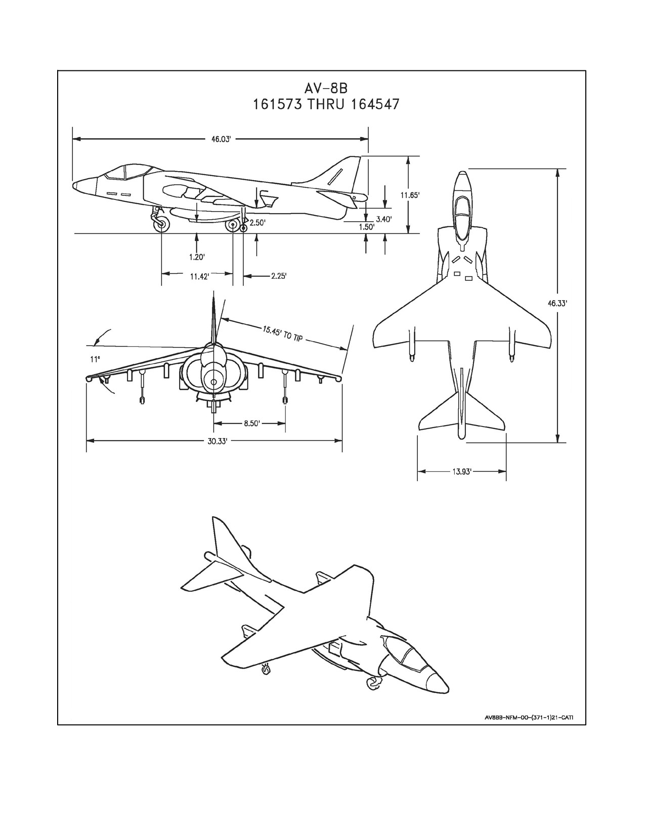
A1-AV8BB-NFM-000
ORIGINAL
62
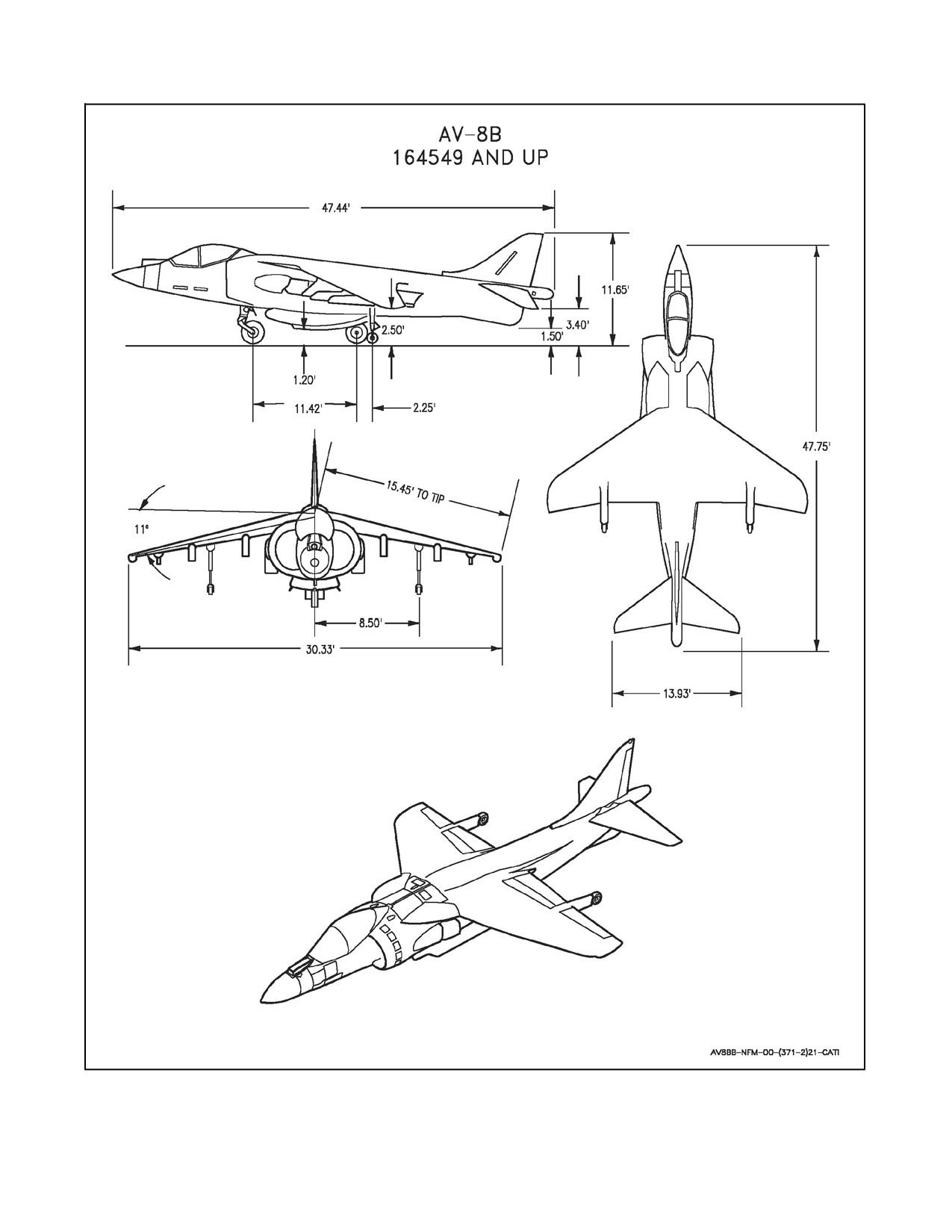
A1-AV8BB-NFM-000
63
ORIGINAL
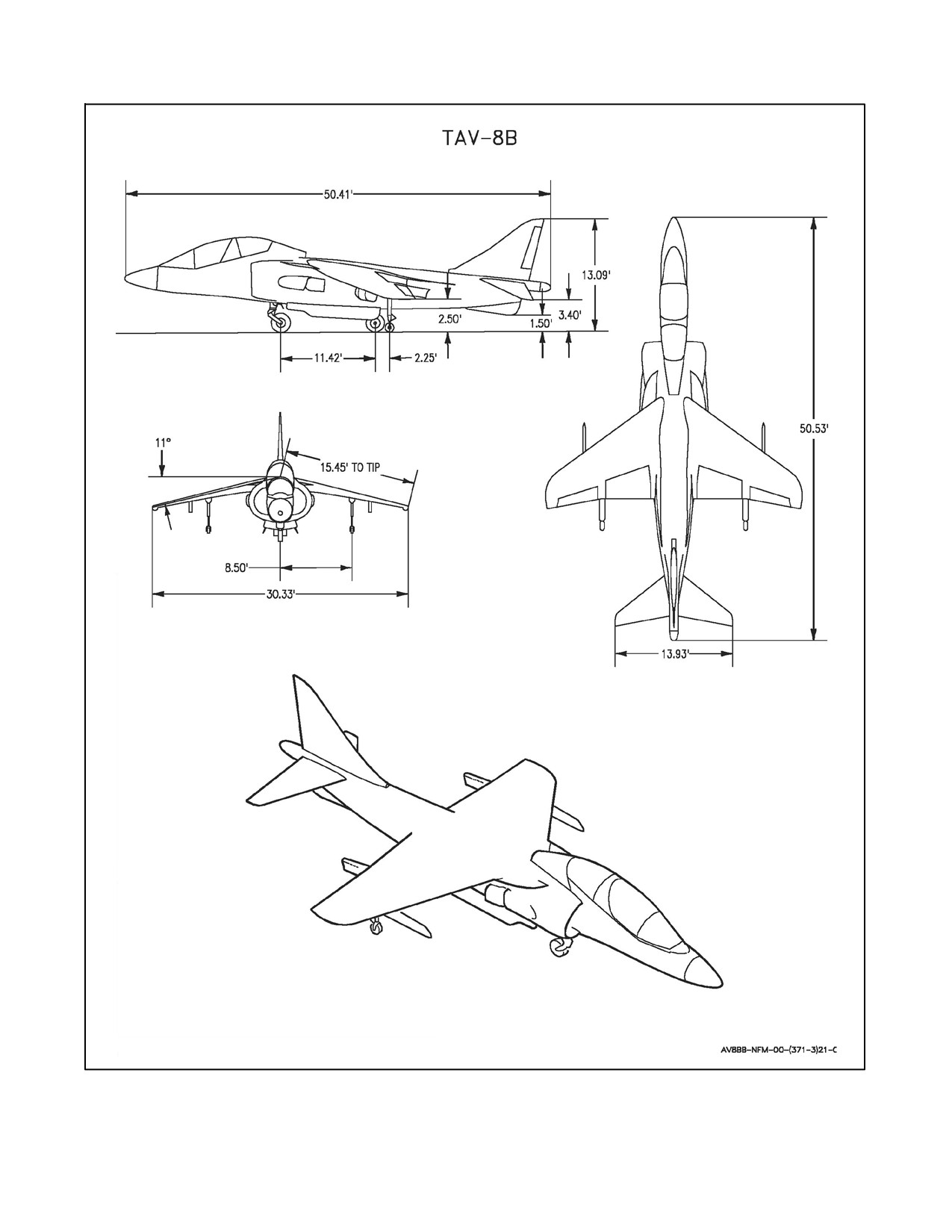
A1-AV8BB-NFM-000
ORIGINAL
64
A1-AV8BB-NFM-000
PART I
The Aircraft
Chapter 1 — Aircraft and Engine
Chapter 2 — Systems
Chapter 3 — Servicing and Handling
Chapter 4 — Operating Limitations
65/(66 blank)
ORIGINAL
//////////////////////////