HELICOPTER, ATTACK, AH-64D LONGBOW APACHE. TECHNICAL MANUAL (2002) - page 10
TM 1-1520-251-10
4.6.7 MANRNG Button. The MANRNG button sets the
active range source to a manually entered value or com-
mands the range source to an automatic mode via the KU.
With auto mode selected the last entered manual range
will remain displayed on the WPN page. This selection is
independent in each crewstation.
4.6.8 SIGHT Select Status Window. The SIGHT select
status window indicates the current state of the sight se-
lect function in that crew station: HMD, TADS (CPG only),
and FCR.
4.6.9 Acquisition (ACQ) Select Status Window. The
ACQ select status window indicates the current state of
the acquisition select function in that crew station; PHS,
GHS, SKR, RFI, FCR, FXD, TADS, TXX, and TRN.
4.6.10 LRFD Status Window. The LRFD status window
indicates the current state of the LRFD Code selection.
4.6.11 LST Status Window. The LST status window in-
dicates the current state of the LST Code selection.
4.7 WPN UTILITY (UTIL) PAGE
LBA0966
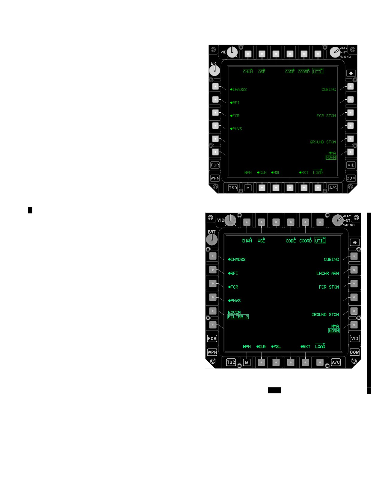
4.7.1
Pilot WPN UTIL Page. The WPN UTIL page
Figure 4-7. Pilot WPN UTIL Page
(figs 4-7 and 4-7A) in the pilot station is as depicted below.
LBA5408
Figure 4-7A.
[
MT
Pilot WPN UTIL Page]
Use or disclosure of this information is subject to the restriction(s) on the title page of this document.
Change 4
4-5
TM 1-1520-251-10
The WPN UTIL page is unique to each crew station and
provides the Pilot the following selections:
• L1
IHADSS button
• L2
RFI Enable button
• L3
FCR button
• L4
PNVS button
• L5
[
MT
EOCCM button]
• R1
CUEING button
• R3
FCR STOW button
• R6
MMA button
a. IHADSS Button. The IHADSS button enables
the IHADSS.
b. RFI Button
The RFI button enables the RFI.
LBA0968
If MMA NORM, the RFI is enabled automatically. If MMA
pinned, the RFI may be enabled manually.
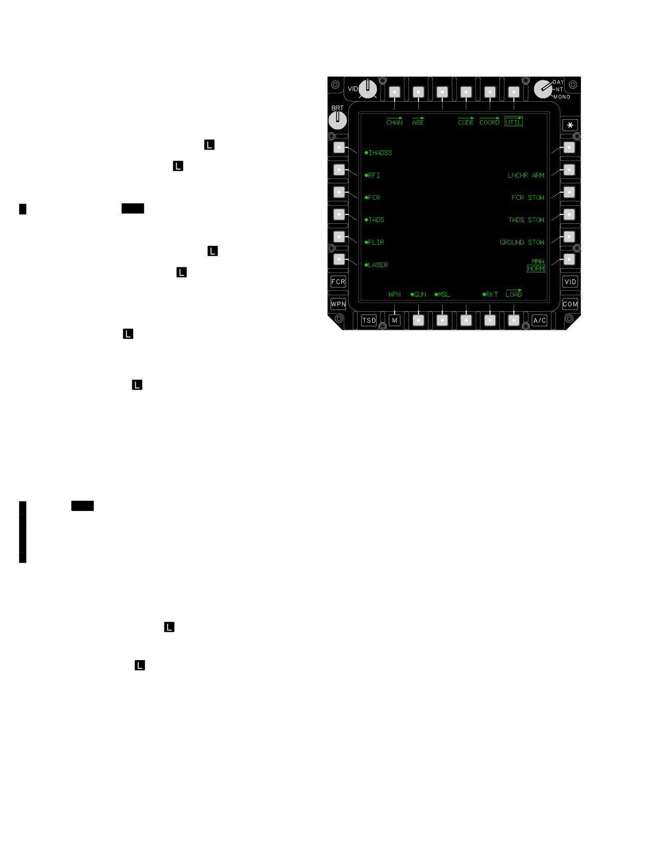
Figure 4-8. CPG WPN UTIL Page
c. FCR Button
The FCR button enables the
FCR. If MMA NORM, this function is selectable.
The WPN UTIL page is unique to each crew station and
provides the CPG the following unique selections:
d. PNVS Button. The PNVS button enables the
PNVS. The PNVS is enabled automatically 1 minute fol-
• L4
TADS button
lowing aircraft power up. This button may be used to en-
• L5
FLIR button
able the PNVS should it become necessary to begin
• L6
LASER button
PNVS powerup sooner than 1 minute.
• R4
TADS STOW button
e.
[
MT
EOCCM Button. The EOCCM button se-
a. TADS Button. The TADS button enables the
lects the type of FLIR EOCCM filter in the pilot station:
TADS. The TADS and FLIR are enabled automatically upon
FILTER 1, CLEAR, or FILTER 2. The selected state is
aircraft power up. The TADS and FLIR are enabled automati-
reflected in the NVS selected status on the flight format on
cally 1 minute following aircraft power up. This button may be
the pilot’s HMD.]
used to enable the TADS should it become necessary to be-
gin TADS/FLIR powerup sooner than 1 minute.
e. CUEING Button. The CUEING button selects
b. FLIR Button. The FLIR button enables the TADS
sensor cueing in the pilot station.
FLIR.
f. FCR STOW Button
The FCR STOW button
c. LASER Button. The LASER button enables the
stows the FCR antenna.
TADS laser transceiver.
d. TADS STOW Button. The TADS STOW button
g. MMA Button
The MMA button selects the
stows the TADS turret.
state of the MMA: NORM or PINNED. For the FCR to be
turned on, MMA NORM must be selected. The default set-
4.8 BORESIGHT PAGE
ting is PINNED. Selecting the MMA button to NORM pow-
ers up the FCR and RFI.
The sight BORESIGHT page accesses IHADSS bore-
sight controls in both crew stations and TADS boresight
4.7.2 CPG WPN UTIL Page. The WPN UTIL page (fig
controls in the CPG station. The sight BORESIGHT page
4-8) in the CPG station is as depicted below.
is unique to each crew station.
Use or disclosure of this information is subject to the restriction(s) on the title page of this document.
4-6
Change 4
TM 1-1520-251-10
4.8.1
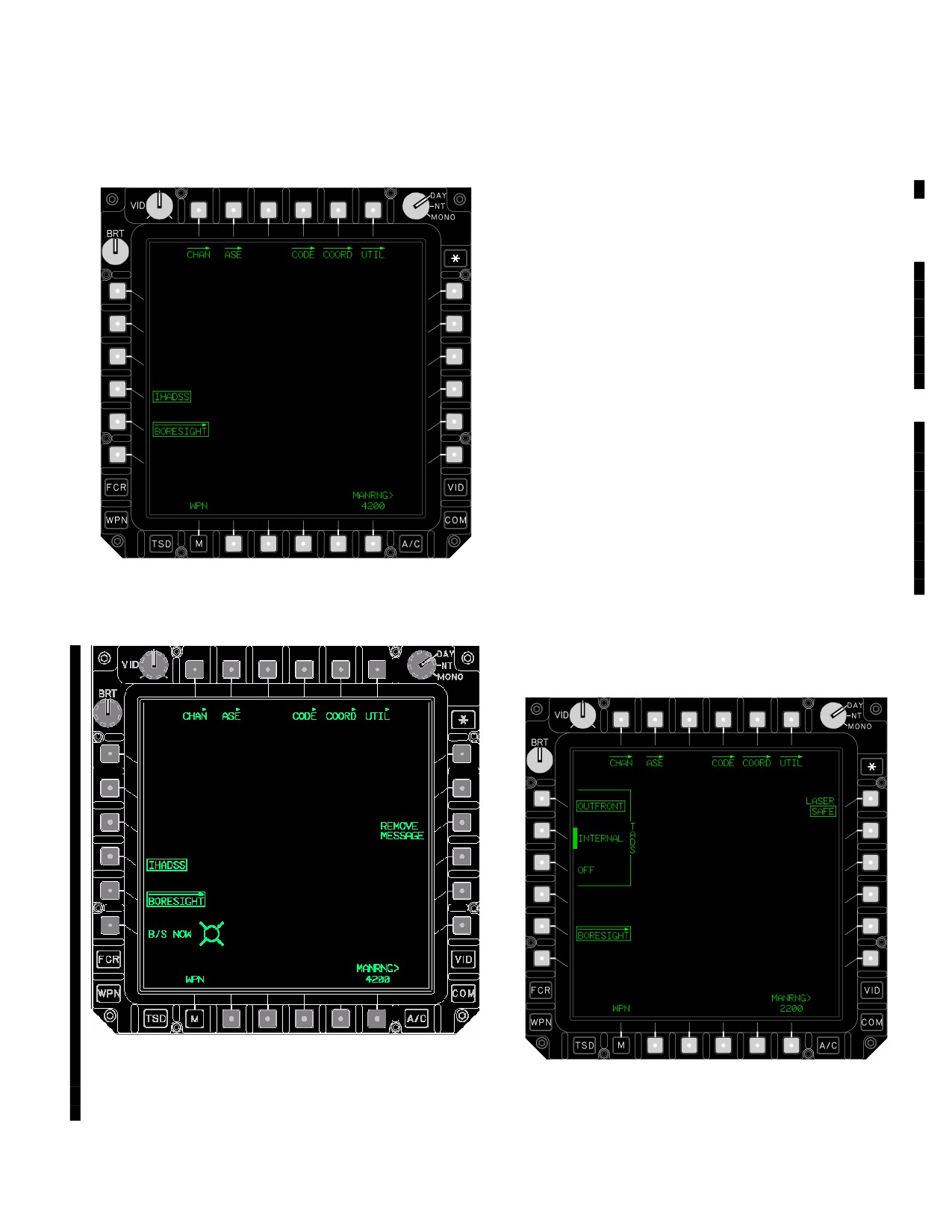
Pilot BORESIGHT Page. The BORESIGHT
• L4
IHADSS button
page (figs 4-9 and 4-9A) in the pilot station provides the
• L5
Sight BORESIGHT button
following selections:
a. IHADSS Button. The IHADSS button is used to
perform IHADSS boresight. Selecting the IHADSS boresight
button causes the IHADSS to enter the boresight mode, turn
on the light in the boresight reticle unit (BRU), and activate
the B/S HMD function on the collective flight control grip.
If the aircraft is equipped with MTADS - MPNVS provi-
sions, selecting the IHADSS boresight button causes the
IHADSS to enter the boresight mode, turn on the light in the
boresight reticle unit (BRU), and display the B/S NOW button
with the MPD cursor within the button selection area (for use
with the collective ENTER switch). The REMOVE MES-
SAGE button is also presented.
b. BORESIGHT Button. The BORESIGHT button
is used to access the BORESIGHT page controls.
c. B/S NOW Button. The B/S NOW button is used to
boresight the IHADSS. Selecting the B/S NOW button stores
IHADSS boresight data.
d. REMOVE MESSAGE Button. The REMOVE
MESSAGE button is used to remove the IHADSS B/S RE-
LBA0554
QUIRED HAD sight status message when the selected sight
is HMD.
Figure
4-9.
Pilot BORESIGHT Page
4.8.2
CPG BORESIGHT Page. The BORESIGHT
page (fig 4-10) in the CPG station provides identical selec-
tions as in the pilot station except for the following:
LBA5492
LBA1019
Figure 4-9A. Pilot BORESIGHT Page (Aircraft
Equipped with MTADS Provisions)
Figure 4-10. CPG BORESIGHT Page
Use or disclosure of this information is subject to the restriction(s) on the title page of this document.
Change 4
4-7
TM 1-1520-251-10
• L1
TADS OUTFRONT button
• L2
TADS INTERNAL button
• L3
TADS OFF button
• R1
LASER button
a. TADS OUTFRONT Button. The OUTFRONT
button is used to perform the outfront boresight proce-
dure. Selecting the TADS OUTFRONT button causes the
TADS to enter the outfront boresight mode. [
MT
This
button is not displayed if the aircraft is equipped with
MTADS.]
b. TADS INTERNAL Button. The TADS INTER-
NAL button is used to perform the internal boresight pro-
cedure. Selecting the TADS INTERNAL button causes
the TADS to enter the internal boresight mode. [
MT
This
selection initiates the automated internal boresight se-
LBA0962
quence (para 4.30).]
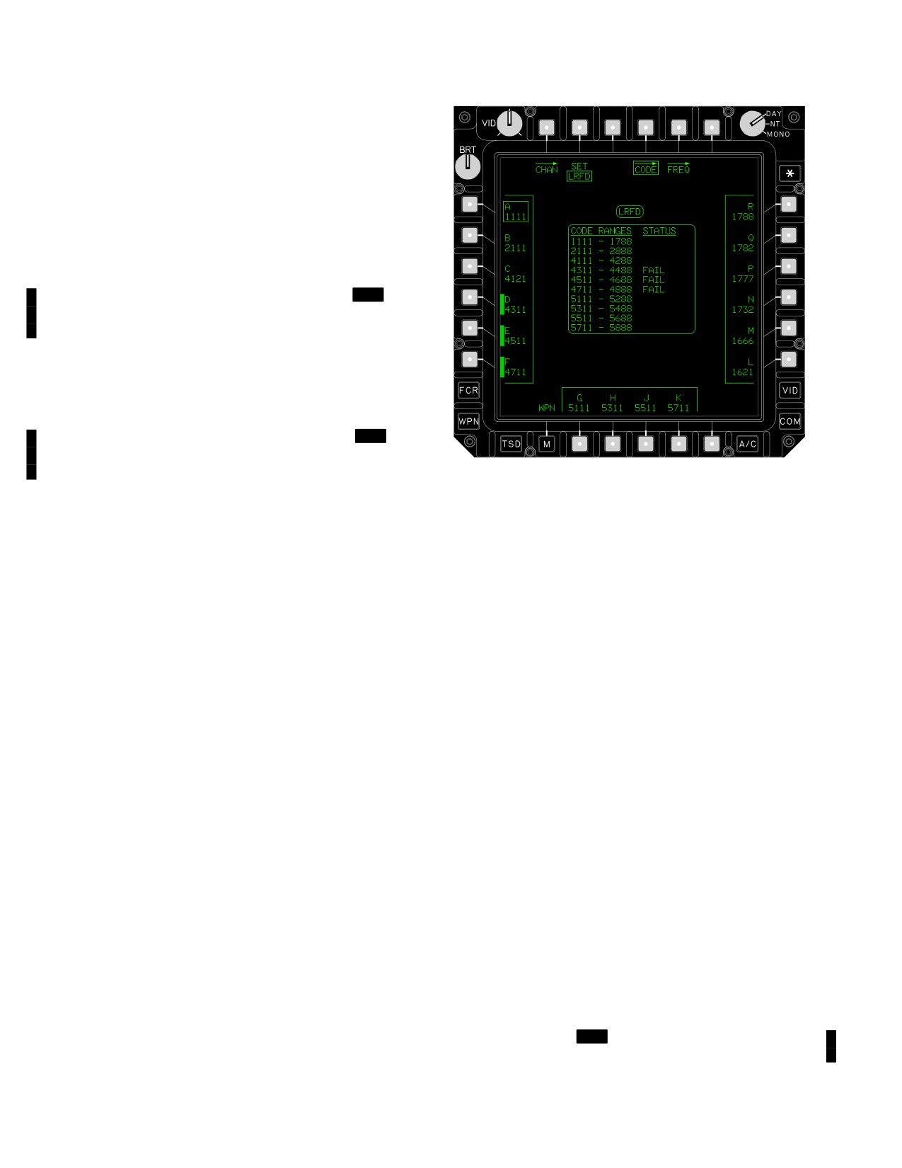
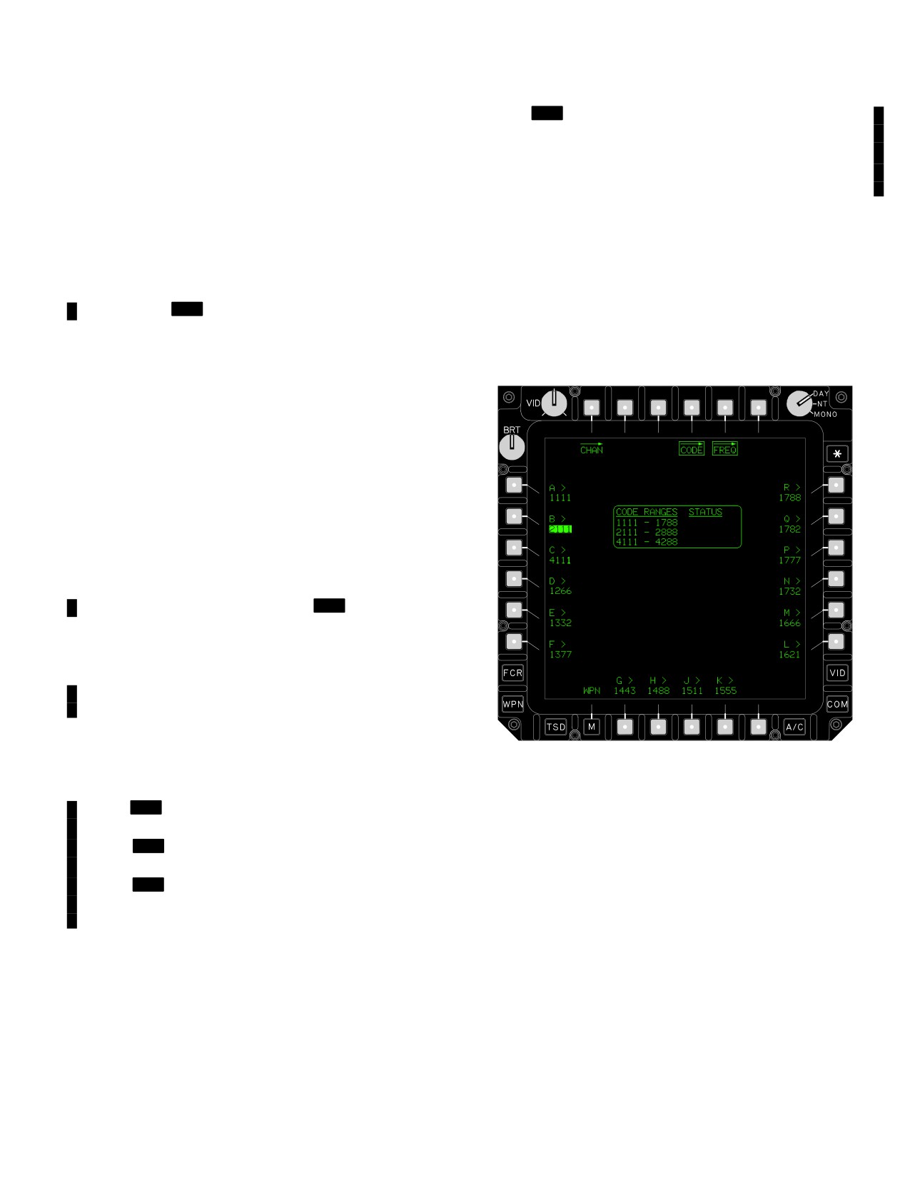
Figure 4-11. CODE Page
c. TADS OFF Button. The OFF button is used to
set the Outfront and Internal boresight modes to off. Se-
• T2
Code SET button
lecting the boresight OFF button causes the TADS to exit
• T4
Laser CODE button
the selected boresight mode.
• T5
Laser FREQ button
• L1 - L6
Code buttons
d. LASER Button. The LASER button is used to
• R1 - R6 Code buttons
ARM and SAFE the LRFD when performing an internal or
outfront boresight procedure. It is displayed in YELLOW
• B2 - B5
Code buttons
when in the ARM state. This button is presented only
4.9.1
SET Button. The laser code SET button sets
when the laser is enabled on the WPN UTIL page and the
which system is to be the recipient of a code selection. Se-
TADS OUTFRONT or TADS INTERNAL option is se-
lecting the SET button sets the state for code selection to
lected. The LASER button will default to the state of the
the LRFD or the LST. This selection is common to both
A/S button on the ARMAMENT panel. When the A/S but-
ton is in the ARM state, the LASER button will be dis-
crew stations.
played with a barrier in the ARM state. When the A/S but-
ton is in the SAFE state, the LASER button is selectable.
4.9.2 Laser Code Buttons.
16 buttons containing the
In the latter case, if the LASER button is in the ARM state
codes and frequencies currently set are used to select the
and a selection is made to leave the BORESIGHT page,
active laser code for the LRFD or LST as selected at the
the LASER button will be set to SAFE.
SET button. A laser code button will be displayed with a
barrier when that code is not available.
4.9 LASER CODE (CODE) PAGE
4.9.3 FREQ Button. The laser FREQ button accesses
stored laser code frequencies.
The laser CODE page (fig 4-11) is used to access 16
4.9.4 LRFD/LST Status Window. The LRFD/LST sta-
stored laser codes. This selection is common to both crew
tus window in the upper area of the laser CODE page indi-
stations. In addition, it is used to provide access to the la-
cates the current LRFD/LST code selections as set by the
ser FREQ page to set the laser frequency for each code.
SET button described above. PIM codes are not available
The CODE page contains the following selections and
for use by the LST. [
MT
PIM codes are available for use
status windows:
by the LST.]
Use or disclosure of this information is subject to the restriction(s) on the title page of this document.
4-8
Change 4
TM 1-1520-251-10
4.9.5
CODE RANGE and KEYWORD STATUS Win-
[
MT
LST/MSL ONLY Indicates that only the LST
dow. The CODE RANGE and STATUS window is lo-
and the Hellfire subsystem is capable of using this
cated in the center area of the laser CODE, FREQ and
code range.
CHAN pages.
“?“ Indicates that data for display of keyword data
is not valid.]
a. CODE RANGE. The CODE RANGE indicates
the laser code ranges which are supported by the laser
4.10 LASER FREQUENCY (FREQ) PAGE
keywords resident on the DTC. The helicopter is capable
of supporting the Tri - Service pulse repetition frequency
The laser FREQ page (fig 4-12) provides access to the la-
(PRF) laser codes and USAF, Hellfire and Copperhead
ser code frequency buttons to change the frequency of
pulse interval modulation (PIM) laser codes. In order for
available laser codes. Selecting the laser FREQ button
the LRFD, [
MT
LST] and Hellfire subsystem to use a
calls up the laser code frequency data entry buttons which
PIM laser code the appropriate keyword, for the specific
appear with respect to the same 16 locations as the laser
code range, is required:
buttons described above.
1111 - 1788
Tri - Service .
PRF
2111 - 2888
USAF .
PIM
4111 - 4288
Hellfire - A .
PIM
4311 - 4488
Hellfire - B .
PIM
4511 - 4688
Hellfire - C .
PIM
4711 - 4888
Hellfire - D .
PIM
5111 - 5288
Copperhead - A .
PIM
5311 - 5488
Copperhead - B .
PIM
5511 - 5688
Copperhead - C .
PIM
5711 - 5888
Copperhead - D .
PIM
b. STATUS Area. The STATUS area indicates the
code range status for the LRFD, [
MT
LST] and Hellfire
subsystems.
FAIL Indicates the DTC laser keyword for this
code range has a checksum error.
N/A Indicates that no equipment is capable of us-
ing this code range.
MSL ONLY Indicates that only the missile subsys-
tem is capable of using this code range.
LBA5244
LRFD ONLY Indicates that only the LRFD is capa-
ble of using this code range.
Figure
4-12.
FREQ Page
[
MT
LST ONL Indicates that only the LST is ca-
pable of using this code range.]
[
MT
LRFD/LST ONLY Indicates that only the
4.10.1
Laser Code Frequency Buttons.
The 16 laser
LRFD and LST is capable of using this code range.]
code frequency buttons are used in conjunction with the
[
MT
LRFD/MSL ONLY Indicates that only the
KU to enter laser code frequencies for each of the avail-
LRFD and the Hellfire subsystem is capable of using
able laser codes. Each character of the four digit entry is
this code range.]
limited in range as listed in paragraph 4.9.5.a.
Use or disclosure of this information is subject to the restriction(s) on the title page of this document.
Change 4
4-8.1/(4-8.2 blank)
TM 1-1520-251-10
HDU shall be stored in the holster located on the right con-
sole. The DEU provides power and video signals to each
4.11 IHADSS DESCRIPTION
crewmember HDU through DAP located in each crew sta-
tion. The BRU in each crew station is used to boresight
the crewmember helmet. Adjustments on the HDU permit
WARNING
image rotation (leveling), collimation with the crewmem-
ber LOS (centering), and focusing. Both crewmembers
In the event of IHADSS failure with gun
can adjust symbol brightness, video brightness, and con-
selected and the HMD as the selected
trast. The CPG controls are on the ORT or TEDAC panel,
sight, the gun will remain at its last com-
while the pilot uses the VIDEO panel.
mand position. Gun firing is inhibited.
When the gun is de-actioned, it will re-
4.13 IHADSS SYMBOLOGY FORMATS
turn to the stowed position.
IHADSS symbology is displayed in one of two formats: the
The IHADSS (fig 4-13) establishes the crewmember line
flight symbology format or the weapons symbology for-
of sight (LOS). The pilot/CPG LOS is provided to the
mat. The flight symbology format consists of those sym-
weapons processor for sensor pointing, symbol genera-
bols, scales, and digital readouts required for pilotage.
tion, ranging, and/or weapons aiming. It also provides the
The weapons symbology format consists of the symbolo-
display of TADS/PNVS video and symbology. The
gy required for employment of the sight and weapons sys-
IHADSS consists of the Integrated Helmet Unit (IHU), the
tems by the CPG. Weapons engagements can be con-
Helmet Display Unit (HDU), Sensor Survey Units (SSU),
ducted using either weapons or flight symbology. Unique
Sight Electronics Unit (SEU), Display Electronics Unit
weapon symbols are displayed in either format when the
(DEU), Display Adjustment panel (DAP), and a Boresight
respective weapon is selected in a crew station. Pilot sta-
Reticle unit (BRU). HMD symbology is generated and
tion HMD provides pilot flight symbology in all normal (2
then mixed with any sensor video underlay by the display
display processor) operating modes. CPG station HMD
processor.
provides CPG flight symbology when the CPG selected
sight is HMD or the CPG NVS MODE switch is set to the
4.12 HELMET DISPLAY UNIT (HDU)
NORM or FIXED position. CPG station HMD provides pi-
lot flight symbology when the ORT video select switch has
The HMD is provided on the HDU in each crew station.
been set to PNVS or the TEDAC PNV video select button
The HDU consists of a CRT with optical elements which
is selected. CPG station provides Weapons symbology
project the selected symbology and sensor imagery onto
whenever it has not been out - prioritized by Flight symbol-
a combining lens. The HDU is attached to the right side of
ogy: When the selected sight is TADS or FCR, the NVS
the helmet during normal use. The attached HDU is ro-
MODE switch is set to OFF; and the ORT video select
tated in front of the right eye for viewing of the display or
switch is set to TADS, FCR, or GS or the TEDAC TAD,
can be rotated vertically away from the eye when not in
FCR, or G/S video select button is selected. Single DP op-
immediate use. When not attached to the helmet, the
eration of the IHADSS is described in paragraph 4.50.3.
Use or disclosure of this information is subject to the restriction(s) on the title page of this document.
Change 3
4-9
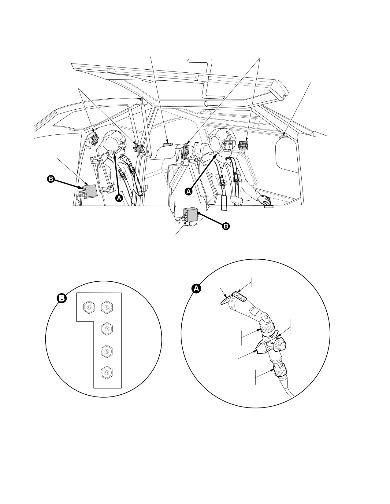
TM 1-1520-251-10
PILOT BORESIGHT
CPG SENSOR
RETICLE UNIT
SURVEYING UNITS
CPG BORESIGHT
PILOT SENSOR
RETICLE UNIT
SURVEYING UNITS
DISPLAY ADJUST
PANEL
DISPLAY ADJUST
PANEL
COMBINER
SLIDING
LENS
CLIP
HORIZON−
TAL
SIZE CTRG
HDU
V
ROTATION
E
STOP
IMAGE
R
ROTATION
SIZE
T
COLLAR
I
C
A
L
HDU CLIP
CTRG
INFINITY
FOCUS
COLLAR
FOCUS
DISPLAY ADJUST PANEL
HELMET DISPLAY UNIT
LBA2449
Figure 4-13. Integrated Helmet and Display Sight System (IHADSS)
Use or disclosure of this information is subject to the restriction(s) on the title page of this document.
4-10
TM 1-1520-251-10
4.14 FLIGHT SYMBOLOGY FORMAT
error greater than 0.3 meters per second exists. The vec-
tor will blank when inertial data is not valid.
Flight symbology provides either crewmember flight in-
2. Acceleration Cue . The Acceleration Cue pro-
formation for use as the primary flight display within the
vides magnitude and direction indication of the aircraft’s
crew station. These flight formats can be configured to ei-
acceleration.
ther Hover (H), Bob-up (B), Transition (T), and Cruise (C)
modes. The flight mode presented can be selected by the
(a) Hover and Bob-up Modes. The origin of the
crewmember using the Cyclic Symbology Select switch.
Acceleration Cue is the outer end of the Velocity Vector
When presented on the HMD, ORT or TEDAC Display
when the vector is at less than maximum scale. The origin
Unit (TDU), all flight symbology is green in color. When
of the Acceleration Cue is the center of the LOS Reticle
presented on the MPD (as can be done using the VIDEO
when the Velocity Vector is at or greater than maximum
Page, VSEL selected), and the MPD is operating in DAY
scale.
or NIGHT mode, the non - green colors noted in the follow-
ing paragraphs will be presented. Conditions under which
(b) Transition Mode. The acceleration cue is al-
flight symbols are presented are defined in paragraphs
ways referenced to the tip of the velocity vector. The sym-
4.13 and 4.50.3.
bol flashes when a greater than 0.3 meters per second er-
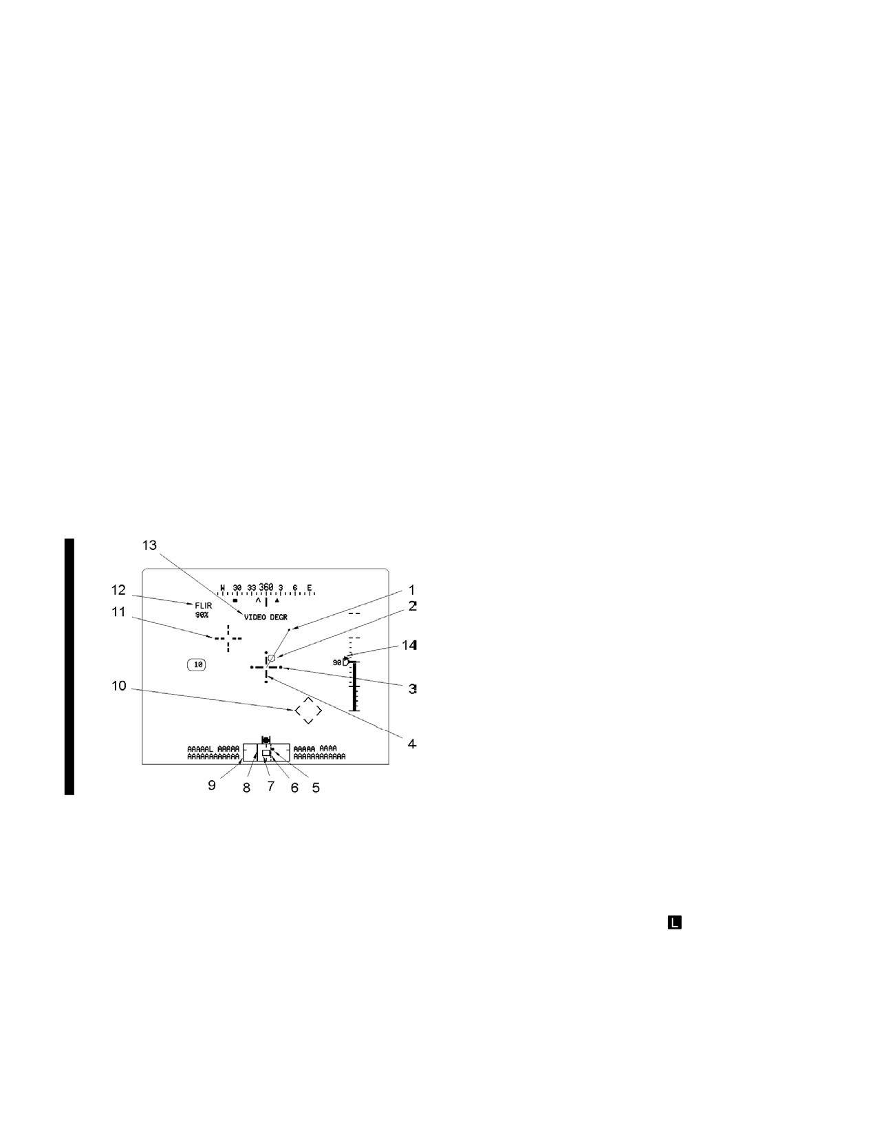
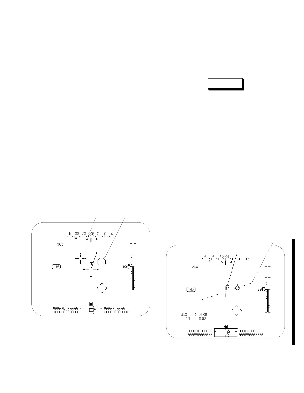
4.14.1 Hover Mode Symbology. The following sym-
ror in inertial data exists and blanks when inertial data is
bols are provided within the Hover Mode symbol set (fig
not valid.
4-14).
3. Cueing Dots. Cueing dots are displayed at the
NOTE
outer tips of the LOS Reticle, and indicate the quadrant
containing the selected acquisition source. A cueing dot
Items not described below function as de-
appears at the upper or lower tip of the reticle when a
scribed in Chapter 2, Section XIV.
change in elevation is required and, appears at the left or
right tip when a change in azimuth is required. They ap-
pear at all four tips of the LOS Reticle and flash when the
IHADSS B/S REQUIRED message is present within the
High Action Display’s Sight Status field. The cueing dots
do not appear when the acquisition source is within 4° of
the line of sight.
4. LOS Reticle . The LOS Reticle is a cross-hair lo-
cated in the center area of the flight format. It represents
the LOS of the crewmember’s selected sight and is used
as an aiming reticle. It is also used as a reference for bore-
sighting as well as for the Head Tracker, the Horizon Line,
the Velocity Vector, the Acceleration Cue, and the Hover
Position Box. The LOS Reticle flashes when the crew-
member’s LOS is invalid or his selected PNVS or TADS
sensor is at its limit. It also flashes when the gun is the se-
lected weapon and the gun system has failed and is not
following the crewmember’s head.
Figure 4-14. Flight Symbology - Hover Mode
5. Cued LOS Dot . The CUED LOS dot is a dynam-
ic dot symbol displayed within the sensor field of regard. It
1. Velocity Vector . The Velocity Vector symbol in-
represents the active acquisition LOS. It is edge limited to
dicates the magnitude and direction of the aircraft velocity
the current field of regard.
relative to the nose of the aircraft. It represents 6 kts
ground speed during hover and bob-up modes and 60 kts
6. FCR Last Centerline
The FCR last scan
ground speed in transition mode. The velocity vector is a
centerline is a dashed, vertical line displayed within the
solid line whose origin is the center of the LOS Reticle.
sensor field of regard. It is displayed to represent the FCR
The line orients in the direction of the helicopter move-
centerline of the most recent scan for which target in-
ment. It extends and withdraws (in length) from the origin
formation is currently being displayed. It is only visible
to indicate longitudinal and lateral velocities of ground
when the current centerline has been repositioned from
movement. The symbol flashes when an inertial velocity
the azimuth of the most recent scan, and the FCR is valid.
Use or disclosure of this information is subject to the restriction(s) on the title page of this document.
Change 4
4-11
TM 1-1520-251-10
7. Field of View Box . The field of view box is a
90°
0°
90°
+30°
+30°
small, dynamic box displayed within the field of regard. it
represents the relative position of the TADS/PNVS 30° X
0°
0°
40° field of view within the field of regard. It is edge limited
to the currently displayed field of regard. The field of view
box is not presented if the field of regard is not presented.
The field of view box represents the pilots HMD on the pi-
60°
60°
lot’s flight formats. It represents the CPG’s HMD when the
90°
0°
90°
120°
120°
CPG’s selected sight is HMD. It represents the TADS
LBA2558
when the CPG’s selected sight is TADS or FCR
Figure 4-16. TADS Field Of Regard
8. FCR Current Centerline
The FCR current
10. Head Tracker . The Head Tracker indicates the
centerline is a solid, vertical line within the current sensor
pilot head position relative to the aircraft datum line. This
field of regard. This line represents the current centerline
is a virtual symbol whose range of display is 30° vertically
of the FCR.
and 40° horizontally about the nose of the helicopter.
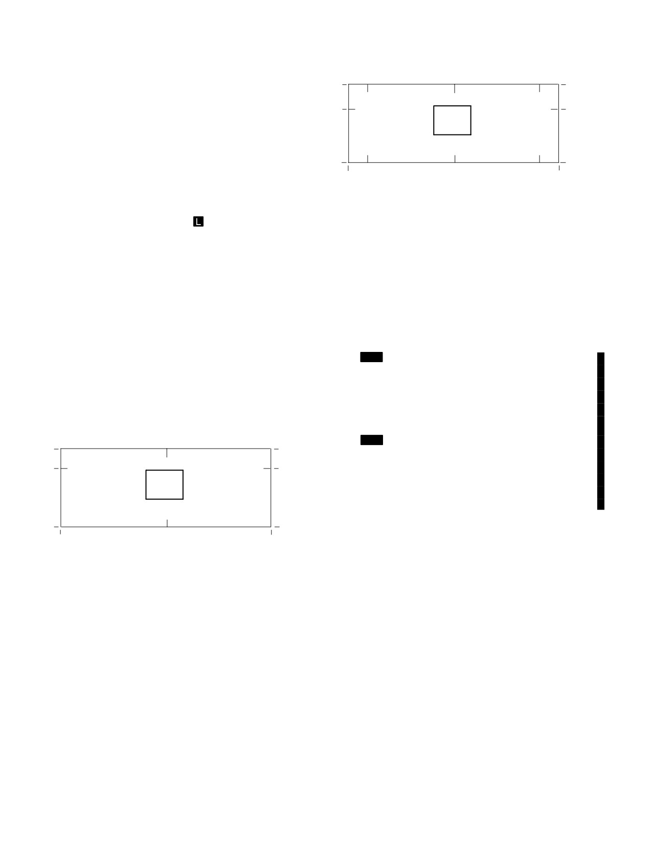
9. Field of Regard. A box representing the selected
11. Cued LOS Reticle . The Cued LOS reticle is a
sensor’s field of regard (FOR) is displayed at the bottom
dashed crosshair symbol which represents the crewmem-
of the flight symbology format. The FOR box edges mark
bers selected acquisition source. In the pilots station the
the AZ limits for each sensor.
Cued LOS reticle is only presented when the CUEING
button is selected.
(a) PNVS FOR. The PNVS field of regard (fig
12.
[
MT
Selected PNVS Sensor. The PNVS se-
4-15) represents the following: The top of the box marks
lected sensor data field presents the name of the selected
+20°, the horizontal tic marks indicate the 0° position, and
PNVS sensor: TV or FLIR. The selected EOCCM FLIR fil-
the bottom of the box marks - 45°. The left side of the box
ter is incorporated into this status: 1FLIR (filter 1). 2FLIR
marks - 90°, the center vertical tic marks indicate 0°, and
(filter 2), or FLIR (clear). TV status is a growth provision
the right side of the box marks +90°.
for an image intensification system.]
13.
[
MT
Video Degraded/Frozen Status. The
0°
+20°
+20°
VIDEO DEGRADED or VIDEO FROZEN status is dis-
played when the respective condition is detected (para
0°
0°
4.50.4A). This status is displayed as confirmation, when
experiencing either condition, that it has been detected by
the system.]
14. Rate of Climb . The rate of climb scale and indi-
45°
45°
0°
cator triangle are located to the left and adjacent to the ra-
90°
90°
dar altitude vertical scale. The scale is presented with a
LBA2557
filled triangle pointer indicating the current rate of climb.
Tic marks designate rates of climb or descent at 100 fpm
Figure 4-15. PNVS Field Of Regard
increments to +/ - 500 fpm, and a single tic mark desig-
nates the 1000 fpm location. When the triangle is in the
(b) TADS FOR. The TADS field of regard (fig
1000 fpm descent limit position, a WHITE data field indi-
4-16) represents the following: The top of the box marks
cating the current rate of descent is presented adjacent to
+30°, the horizontal tic marks indicate the 0° position, and
the triangle. The data field shall present the rate of de-
the bottom of the box marks - 60°. The left side of the box
scent to the nearest 100 fpm when the rate of descent ex-
marks - 120°, the left vertical tic marks indicate - 90°, the
ceeds 1000 fpm. The rate of climb limit data field is re-
center vertical tic marks indicate 0°, the right vertical tic
served for barometric altitude. Rates of climb/descent are
marks indicate +90°, and the right side of the box marks
not presented if the EGI is not providing valid vertical
+120°.
speed information.
Use or disclosure of this information is subject to the restriction(s) on the title page of this document.
4-12
Change 4
TM 1-1520-251-10
15. Additional Symbols. The following symbols are
Scale. It represent the heading of the helicopter upon the
defined in chapter 2 for the FLT Page:
initiation of the Bob-up Mode. It remains at that heading
until the Bob-up Mode is disengaged or heading becomes
• Airspeed
invalid. If heading was not valid upon bob-up initiation or
• Altitude Hold
the heading scale is not presented, this symbol is not dis-
• Attitude Hold
played.
• Engine Torque
• G Status
WARNING
• Heading Scale
• ADF Bearing
The Bob-up box may drift in a stationary
• Alternate Crew member Sensor Bearing
hover. Outside cockpit visual cues must
be the principle source of rotor clear-
• Command Heading
ance.
• FCR Centerline Bearing
• Lubber Line
2. Bob-up Box. The bob-up box is a dynamic box
displayed in the shape of an octagon. It initializes at the
• Radar Altitude
center of the LOS Reticle upon selection of the Bob-up
• Radar Altitude HI
Mode. The bob-up box moves about the format to indicate
• Radar Altitude LO
the relative position of the helicopter to the spot on the
• Radar Altitude Vertical Scale
earth where the box was initialized. If the bob-up box
moves to the maximum displacement on the format, it
• Rate of Climb
hangs at the edge and continues to move about the edge
• Skid/Slip Ball
of the format to indicate the relative direction to the initial-
• Turbine Gas Temperature (TGT)
ization point. The bob-up box shows an approximately 12
ft square area on the ground. Maximum displacement to
4.14.2 Bob-up Mode Symbology. The Bob-up Mode
the edge of the format represents approximately 40 ft lat-
symbols (fig 4-17) consist of the Hover Mode symbols,
erally or 40 ft longitudinally. The symbol is not presented
with the following additions:
when inertial data is not valid.
1
2
4.14.3 Transition Mode Symbology. The Transition
Mode symbols (fig 4-18) consist of the Hover Mode sym-
bols, with the following additions:
1
LBA2025A
Figure 4-17. Flight Symbology - Bob-up Mode
LBA0444B
1. Bob-up Heading. The bob-up heading chevron
is presented along the bottom of the magnetic Heading
Figure 4-18. Flight Symbology - Transition Mode
Use or disclosure of this information is subject to the restriction(s) on the title page of this document.
Change 4
4-13
TM 1-1520-251-10
NOTE
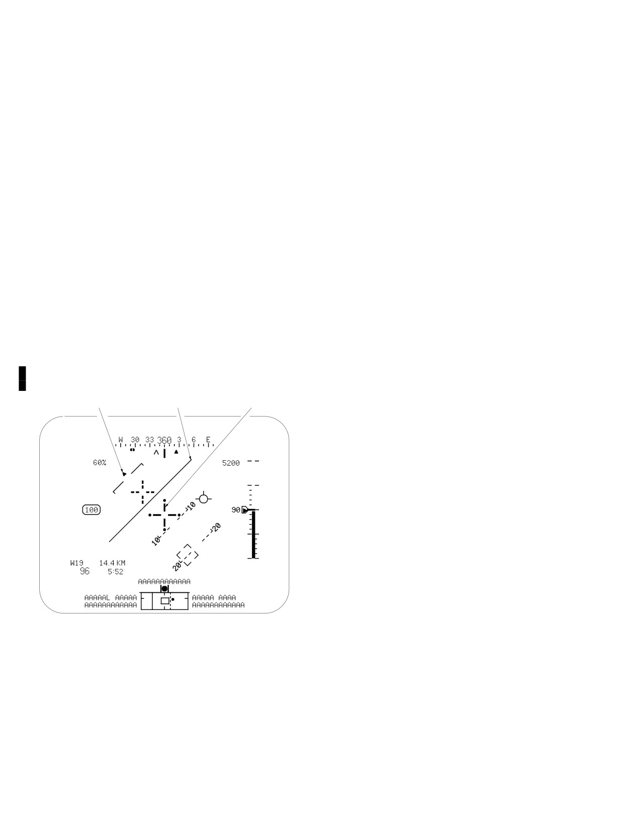
4.14.4 Cruise Mode Symbology. The Cruise Mode
The horizon line and attitude indicator hori-
symbols (fig 4-19) consist of the Transition Mode symbols,
zon bar will appear to jump when changing
with the following additions or changes:
between transition and cruise modes. This
1. Bank Angle. The bank angle presentation oper-
is due to the difference in display scaling/
ates as described in chapter 2 for the FLT page. However,
rate of movement between the horizon line
the bank angle triangle is presented without the
(2:1 movement) and the horizon bar (4:1
associated tic mark scale on the Cruise Mode flight for-
movement).
mat.
1. Horizon Line. The horizon line is a brown dy-
namic split dashed line positioned horizontally in the cen-
NOTE
ter of the format about the center of the LOS reticle. It rep-
The horizon line and attitude indicator hori-
resents an artificial horizon relative to the LOS reticle. The
zon bar will appear to jump when changing
symbol moves within ±30° in pitch, and hangs at the end
between transition and cruise modes. This
positions of this range for pitch attitudes greater than
is due to the difference in display scaling/
±30°. The horizon line is not presented when inertial data
rate of movement between the horizon line
is not valid
(2:1 movement) and the horizon bar (4:1
2. Additional Symbols. The following symbols are
movement).
defined in chapter 2 for the FLT Page:
2. Attitude Indicator. The attitude indicator pre-
• Destination Point
sentation operates as described in chapter 2 for the FLT
• Distance to Go
page, however, to offer less obstruction of the real-world
• Time to Go
or imagery backg2round, 5° tic marks are not presented,
• Groundspeed
and the scaling has been changed.
• Flight Path
3. LOS Reticle. In Cruise Mode, the LOS reticle is a
• Nav Fly - To
bold cross-hair located in the center of the cruise mode
1
2
3
flight format. It represents the LOS of the pilots selected
sight and is used as an aiming reticle. It is also used as a
reference for boresighting and the pilot head tracker. The
reticle flashes when the pilots line of sight is invalid or the
selected sensor is at its limit. It also flashes when the gun
is selected and the gun system has failed.
LBA0445A
Figure 4-19. Flight Symbology - Cruise Mode
Use or disclosure of this information is subject to the restriction(s) on the title page of this document.
4-14
Change 4
TM 1-1520-251-10
4. Barometric or Inertial Altitude. The barometric
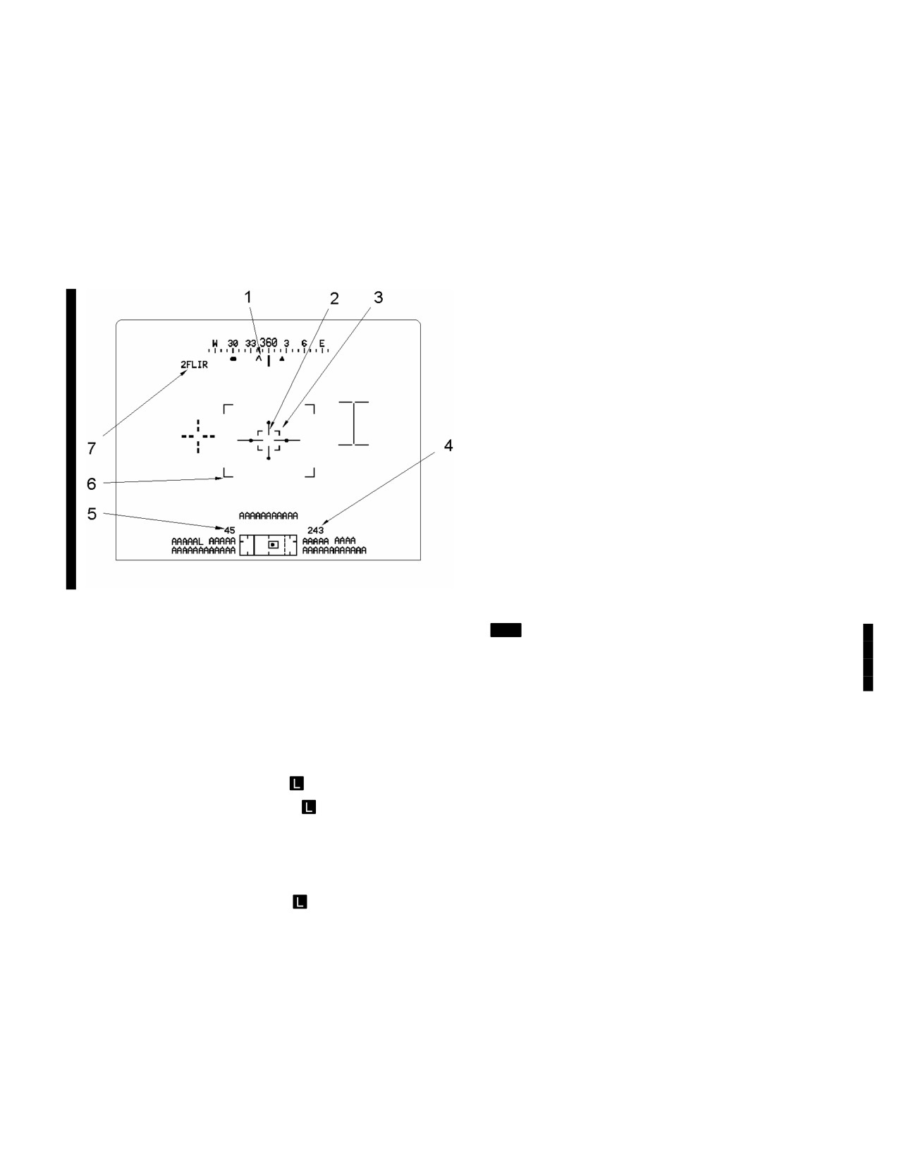
4.15.1 Weapon Symbology. When presented on the
or inertial altitude, is defined in chapter 2 for the FLT page.
HMD or ORT, all weapon symbology is green in color. When
presented on the MPD (as can be done using the VIDEO
4.15 WEAPON SYMBOLOGY FORMAT
Page, VSEL selected), and the MPD is operating in DAY or
The weapon symbology format (fig 4-20) is displayed in
NIGHT mode, the non-green colors noted in the following
the CPG station on the TDU, ORT HOD/HDD and HMD
paragraphs will be presented.
when FCR or TADS is the selected sight, and the HMD is
1. CPG LOS Bearing. The CPG LOS Bearing is a
not being used for NVS, as described in paragraphs 4.13
chevron displayed along the bottom of the magnetic head-
and 4.50.3.
ing scale (in place of the command heading). It represents
the LOS direction of the CPG HMD or TADS sensor in de-
grees of azimuth. If FCR is the CPG selected sight, it rep-
resents the LOS direction of the TADS sensor. If the head-
ing scale is not presented, this symbol is not displayed.
2. TADS LOS Reticle. The TADS LOS Reticle is a
crosshair symbol which represents the TADS line of sight.
It is internally generated by the TEU and is displayed as a
part of TADS imagery. The TADS LOS reticle will flash
when the gun is the selected weapon and the gun system
has failed. The TADS LOS reticle color corresponds to the
video color.
3. Image Auto Track Gates. The Image Auto Track
(IAT) gates are a set of four dynamic gate symbols dis-
played only when the IAT/OFS switch is activated. The
IAT gates originate at the TADS LOS reticle and move out
in the format to capture a selected object with FLIR or
DTV imagery. The IAT gates will attempt to capture an ob-
ject contrast according to the position of the IAT POLAR-
ITY switch. The IAT gates color corresponds to the video
color.
Figure 4-20. Weapons Symbology Format
[
MT
Unique primary and secondary track symbols are dis-
played when activating the IAT/OFS switch. Objects are
The following symbols, defined in Chapter 2 for the FLT
tracked using edge tracking and inertial tracking (para
Page, are also presented in the Weapon format and in
4.26.2).]
Chapter 4 for the flight symbology format:
• Cued LOS reticle
4. Radar Altitude. The radar altitude presentation
operates as described in chapter 2 for the FLT page. It is
• Cueing dots
located to the right of the field of regard, above the high
• Cued LOS dot
action display.
5. Airspeed. The airspeed presentation operates as
• FCR current centerline
described in chapter 2 for the FLT page. Its location on the
• FCR last scan centerline
weapon format is to the left of the field of regard, above
• Field of view box
the high action display.
6. TADS FOV Brackets. The TADS FOV brackets
• TADS FOR box
are displayed in the center area of the format surrounding
• Heading scale
the LOS reticle. They appear as corner marks on the dis-
• FCR centerline bearing
play to indicate the amount of the currently displayed
imagery of TADS that will be displayed in the next narrow-
• Alternate sensor bearing
er field of view (FOV). They only appear when a next nar-
• LOS reticle
rower FOV is available, and TADS imagery is presented
• Lubber line
on the format.
Use or disclosure of this information is subject to the restriction(s) on the title page of this document.
Change 4
4-15
TM 1-1520-251-10
7. TADS Selected Sensor. The TADS selected sen-
when pylon articulation is in process. The cursor shall be
sor data field presents the name of the selected TADS sen-
dashed when a safety or performance inhibit (Table 4-5) is
sor: DVO (ORT only), DTV, or FLIR. [
MT
The selected
in force, indicating crew action is required prior to firing
EOCCM FLIR filter is incorporated into this status: 1FLIR
rockets. A gap in the center vertical line indicates the py-
(filter 1). 2FLIR (filter 2), or FLIR (clear).] The TADS se-
lons are in ground stow position (Figure 4-21) shows the
lected sensor data field is not presented if there is no TADS
four possible appearances of the rocket steering cursor:
video shown.
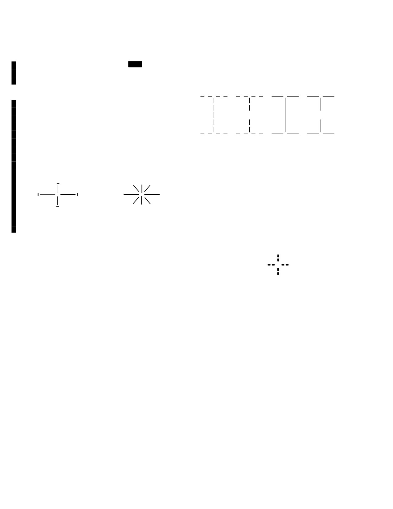
8. LMC On Indicator. The LMC On (fig 4-20A) sym-
bol consists of four short end - cap lines displayed near the
end of the TADS LOS reiticle lines. If the aircraft is
equipped with MTADS - PNVS provisions, this indicator is
displayed when LMC is on.
9. Laser Firing Indicator. The Laser Firing indica-
(1)
(2)
(3)
(4)
LBA1999
tor (fig 4-20A) consists of a large “X” symbol displayed in
conjunction with the TADS LOS reticle. If the aircraft is
Figure 4-21. Rocket Steering Cursors
equipped with MTADS - PNVS provisions, this indicator is
(1) Articulating/inhibited rocket steering cursor.
displayed when the LRFD is lasing.
(2) Stowed/inhibited rocket steering cursor.
(3) Articulating rocket steering cursor.
(4) Stowed rocket steering cursor.
LMC On
Laser Firing Indicator
b. Fixed Gun Aiming Reticle. The fixed gun aiming
reticle (fig 4-22) is the same graphically as the cued LOS
Figure 4-20A. LMC On and Laser Firing Indicators
reticle. It represents a fixed impact point for a given range.
It is presented only when the crewmember actions the gun
4.15.2 Weapon Symbols. Unique weapons symbols are
in the fixed mode.
presented on the flight and weapon formats to indicate
weapon aiming and status information.
a. Rocket Steering Cursor. The rocket steering
cursor is a dynamic I-beam symbol which indicates the
delivery mode and how to point the aircraft for the rocket
LBA2000
delivery. If the CPG has actioned rockets, the rocket steer-
ing cursor is presented on both pilot and CPG formats. If
Figure 4-22. Fixed Gun Aiming Reticle
the pilot has actioned rockets, the pilots rocket steering
cursor is presented only on the pilot’s displays. The cursor
c. Gun DH Reticle. The Gun DH Reticle is the same
moves about in the format to indicate the azimuth and
graphically as the cued LOS reticle. The position of this
elevation position of the helicopter in relation to the se-
symbol is controlled by the MAN TRK thumb force control-
lected sight LOS to provide a steering cue to the crew-
ler to designate the impact point/area of the gun rounds
member. The cursor is displayed with a solid vertical line
following dynamic harmonization gun firing.
Use or disclosure of this information is subject to the restriction(s) on the title page of this document.
4-16
Change 4
TM 1-1520-251-10
d. Missile Constraints Box. The Hellfire missile
(1)
(2)
constraints box (fig 4-23) is used to indicate the delivery
mode and direction to orient the aircraft for the Hellfire
missile launch. A dashed line type indicates the missiles
are out of constraints. A solid line indicates the missiles
are in constraints. If a SAL missile is actioned but not
tracking, the constraints box size is set to LOAL (small
box). If the missile transitions into TRACK mode, the
constraints box will be set to LOBL (large box). RF missile
(3)
(4)
LBA2001
constraints box is based on target handover data, which
determines actual missile trajectory mode. If the missile
Figure 4-23. Missile Constraint Boxes
does not enter a LOBL RADAR mode, the constraints box
(1) LOAL out-of-constraints missile box.
is set to LOAL. The constraints box size does not directly
(2) LOAL in-constraints missile box.
correlate to an angle (such as seeker FOV). For SAL mis-
(3) LOBL out-of-constraints missile box.
siles, the allowable angle is larger for LOBL (20°) than for
(4) LOBL in-constraints missile box.
LOAL (7.5°). Alignment of the aircraft to the target LOS is
4.15.3 C-Scope Symbols
. FCR symbols are present-
not as critical so the LOBL constraints box is larger. For
ed in the C-Scope format on the flight and weapon symbolo-
RF missiles in either LOAL or LOBL trajectory mode, the
gy formats. Target symbols are displayed in GTM, RMAP, or
allowable angle is 20°. If the RF missile is tracking and the
ATM. Terrain profile lines and obstacle symbols are displayed
target range is w
1 km, the allowable angle is 20°. If the
in TPM.
RF missile is tracking and the target range is t
1 km, the
a. FCR Target Symbols. Target symbols (fig 4-24)
allowable angle is 5°.
are provided to indicate the azimuth and elevation loca-
tion of targets detected during last scan. Target symbol
color is IAW the FCR page presentation of targets de-
scribed in para 4.44.4
Use or disclosure of this information is subject to the restriction(s) on the title page of this document.
Change 4
4-16.1/(4-16.2 blank)
TM 1-1520-251-10
W
30
33
360
3
6
E
75%
FLIR
ÓÓ
ÓÓ
90
ÓÓ
Ó ÓÓ
ÓÓ
AAAAAAAAAAAA
47
90
AAAAA
L
AAAAAL AAAAA
AAAAAAAAAAAA
AAAA
AAAAAAAAAA
LBA2005A
LBA2002A
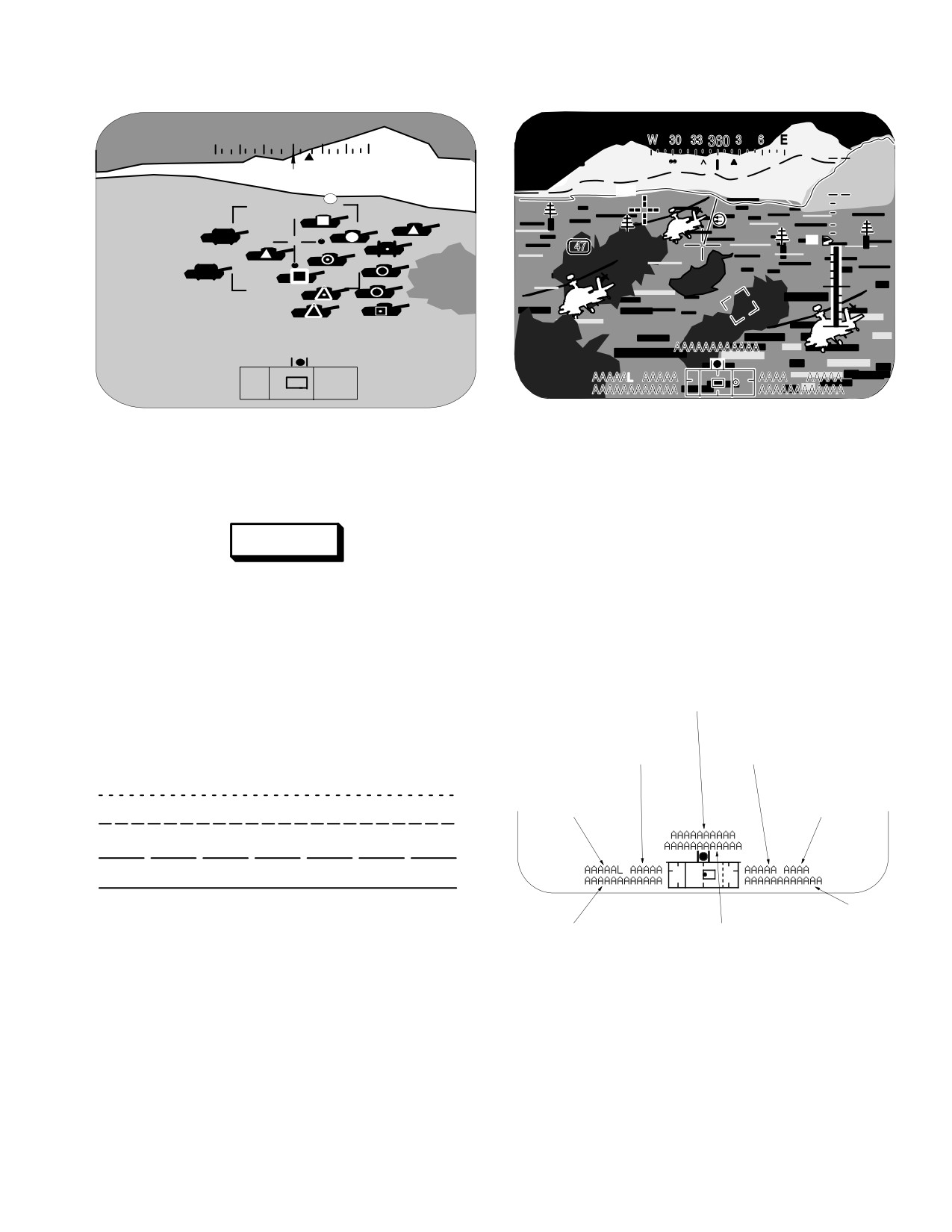
Figure 4-26. FCR Profile Lines and Obstacles in
Figure 4-24. FCR Target Symbols in C - Scope
C-Scope
(example TADS FLIR WFOV)
4.16 HIGH ACTION DISPLAY (HAD) FORMAT
WARNING
The HAD is located along the bottom of the weapons and
flight symbology formats (fig 4-27). It is subdivided into
The terrain profiling mode of the FCR
seven status message fields and provides information in-
shall not be relied upon for primary pilot-
dependently by crew station. The messages are typically
age information.
presented in priority order based on the selected sight
and/or weapon system. Messages on MPD will be in
b. Profile Line Symbols. Terrain profile lines (fig
green unless otherwise indicated in the following tables.
4-25) are provided to indicate the greatest elevation at up
to four ranges from the helicopter. The number of lines
OWNER CUE
displayed is selected on the FCR page, TPM Format. The
solid (nearest) line is shown WHITE in color.
RANGE AND
WEAPON
RANGE SOURCE
CONTROL
FURTHEST FROM HELICOPTER
ACQUISITION
SIGHT SELECT
SELECT STATUS
STATUS
NEAREST HELICOPTER
WEAPON
STATUS
LBA2003
SIGHT STATUS
WEAPON INHIBIT
LBA2006A
Figure 4-25. Terrain Profile Line Dash Patterns
Figure 4-27. Pilot and CPG HAD Format
c. Obstacle Symbol. Obstacle symbols are pro-
vided to indicate towers or other items with significant
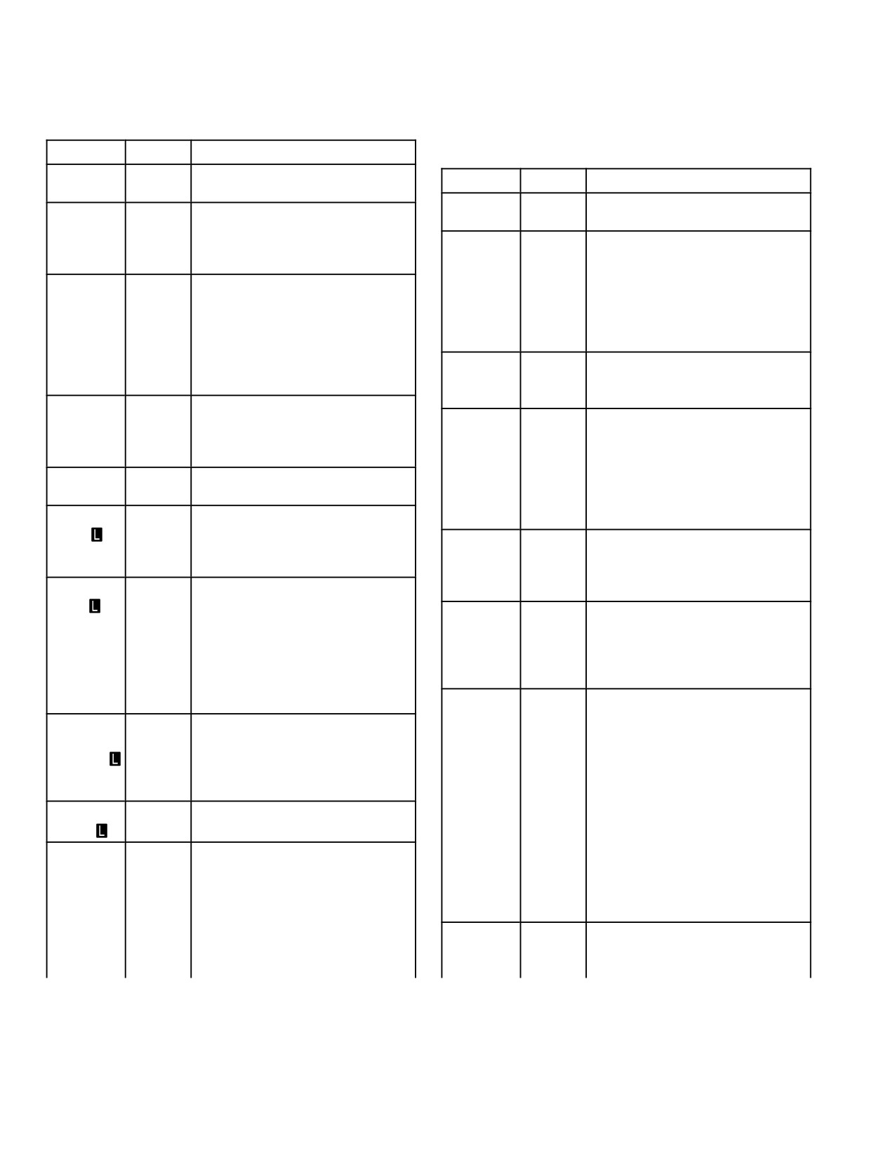
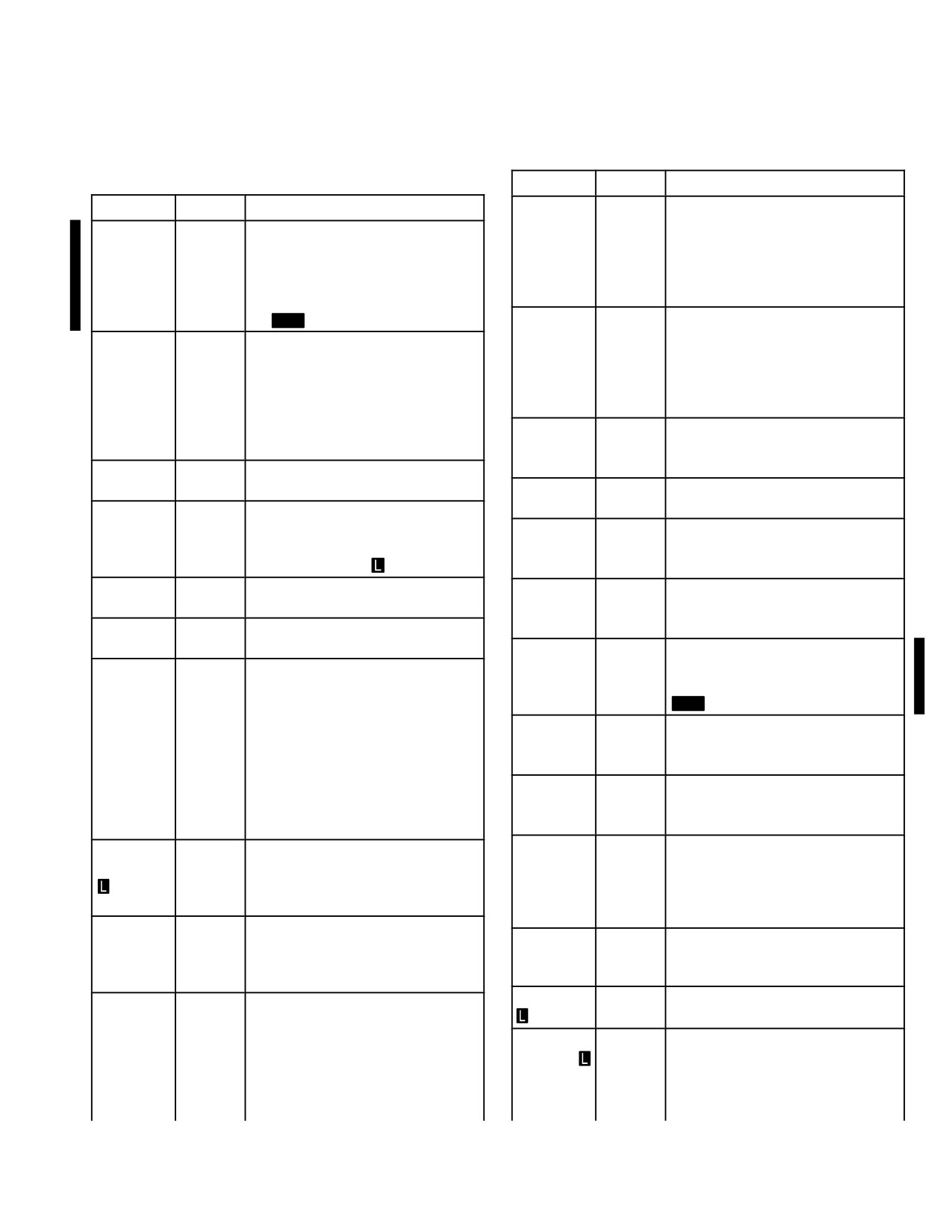
4.16.1 Sight Status Field. The HAD sight status field
changes in vertical elevation plus radar cross section and
(Table 4-1) is located on the bottom left of the display field
minimum height detected by the FCR in Terrain Profiles
and occupies 12 character spaces. This field provides
mode (fig 4-26). The obstacles are YELLOW in color. Ob-
sight status messages in the priority order based on the
stacles are not presented if FCR data is not valid.
crew station and selected sight.
Use or disclosure of this information is subject to the restriction(s) on the title page of this document.
4-17
TM 1-1520-251-10
Table 4-1. HAD Sight Status Field Messages
Table 4 - 1. HAD Sight Status Field Messages (cont)
Message
Color
Description
BOT
(Beginning of Tape) The tape is
Message
Color
Description
at the beginning position.
FIXED
The selected sight (FCR/TADS)
CHK
White
The VCR door is not latched or
is in the fixed position.
the tape presence is not de-
FLIR
The TADS FLIR has not cooled
tected. The crewmember should
check the tape or tape door.
NOT
down sufficiently for optimum
COOL
performance; cool down should
CUE
The TADS cue update boresight
not exceed 15 minutes. The
UPDT
has been selected by placing
message alternates (FLIR, then
the IAT in MANUAL and the
NOT COOL) at the alternating
SLAVE switch OFF when
text rate. Applies only to CPG.
BORESITE has been selected
FLIR OFF
The FLIR has been turned OFF,
via the MPD. Applies only to
the TADS is still powered. Ap-
CPG
plies only to CPG.
ENERGY
Laser energy has been detected
LOW
as low. Presented only when la-
HF TOF-
Indicates time (in seconds) until
ser is firing. Applies only to
NN
missile impact for a remote
CPG.
launch. If more than one missile
is in flight, the display will show
EOT
(End of Tape) The VCR tape is
TOF for the missile first
at the end; no tape remains.
launched, then the subsequently
FCR FAIL
White
The FCR has been detected as
launched missiles.
NO - GO, and the FCR antenna
IHADSS
IHADSS boresight required. This
defaults to fixed forward, if pos-
B/S RE-
message alternates (IHADSS
sible.
QUIRED
B/S, then REQUIRED) at the al-
FCR HOT
Yellow
An impending overtemperature
ternating text rate.
condition exists (80 - 90% of
IHADSS
White
The IHADSS has been detected
overheat threshold) within the
FAIL
as NO - GO for that crewstation
FCR components. The FCR will
by the DMS. The IHADSS LOS
automatically shut down when
defaults to fixed forward for the
the temperature limit is exceed-
affected crewstation.
ed unless the FCR TEMP
ORIDE button is selected.
IHADSS
White
This condition is caused by any
LOS
one of the following conditions:
FCR
White
The FCR is not available be-
INVALID
IHADSS failure, IHADSS power
NOT
cause of BIT or Power-Up. The
being off, blockage of the line-of-
READY
message alternates (FCR, then
sight between the SSU and hel-
NOT READY) at the alternating
met, or the head of the crew-
text rate.
member being outside the head-
FCR
The FCR is transmitting.
motion box. The IHADSS LOS is
XMIT
frozen at the last valid computa-
tion until the LOS is computed
FIRE
The minimum interval between
as valid. The message alter-
MSLS
launches has elapsed in a rapid
nates (IHADSS LOS, then IN-
fire Hellfire missile engagement,
VALID) at the alternating text
and more than one missile is
rate.
present in the priority channel
after launch of a missile. This
INTER-
The TADS internal boresight has
message is displayed for 2 se-
NAL B/S
been selected via the MPD. Ap-
conds.
plies only to CPG.
Use or disclosure of this information is subject to the restriction(s) on the title page of this document.
4-18
Change 3
TM 1-1520-251-10
Table 4 - 1. HAD Sight Status Field Messages (cont)
Table 4 - 1. HAD Sight Status Field Messages (cont)
Message
Color
Description
Message
Color
Description
NVS B/S
White
The weapon processor has de-
ERR
tected an alteration of internal
INTER-
White
The system has determined a
values affecting the PNVS align-
NAL B/
TADS internal boresight is nec-
ment. The PNVS will function
S.. RE-
essary. The boresight will be re-
normally but without alignment
QUIRED
quired at system power - up and
correction.
once every 50 minutes thereaf-
ter
MT
NVS
White
The TADS Electronics Unit has
DIRECT
been detected as NO - GO. The
LASE NN
The laser designator must be
PNVS turret is being directed by
TRGT
lasing the target for missile ter-
the weapons processor and its
minal guidance. The message is
azimuth is limited to 75° left and
displayed for 4 seconds starting
right.
at TOF=12 calculated missile
time of flight during LOAL
NVS FAIL
White
DMS has determined the PNVS
launches.
turret or electronics or the TADS
(if it is the NVS) as NO - GO.
LASER
White
Indicates LRF/D Failure.
FAIL
Applies only to CPG.
NVS
The operator has selected the
FIXED
NVS fixed mode.
LIMITS
The selected sight, TADS, FCR,
or PNVS (in NVS mode) is at a
NVS NOT
White
The PNVS FLIR or TADS FLIR
limit. Also applies to TADS or
COOL
has not cooled down for opti-
FCR when linked
mum performance.
LRFD
White
The selected LRFD laser code is
OUT-
The TADS outfront boresight
CODE ?
not usable. Applies only to CPG.
FRONT
has been selected via the MPD.
B/S
Applies only to CPG.
LST
White
The selected LST laser code is
CODE ?
not usable. Applies only to CPG.
PNVS
White
At power - up, the PNVS is per-
ARTY
Indicates time (in seconds) until
SBIT..IN
forming a 30 second functional
TOF = NN
artillery rounds impact for a call
PROG-
test of electronic equipment
for fire mission. Time of flight
RESS
MT
countdown will begin when the
RECORD
White
The video tape recorder is com-
message is opened and is
FAIL
manded to record video, but it is
based on estimated TOF deter-
not recording.
mined by the sender. If more
RE-
The video tape recorder is re-
than one “shot” time is issued,
time of flight is based upon the
CORD-
cording video.
ING
most recently opened message.
REMOTE
The Hellfire missile system is set
MMA
The operator has indicated to
up for remote missile launch,
PINNED
the system that the MMA is
i.e., the priority missile channel
pinned in a fixed forward posi-
does not match the LRFD code.
tion.
Applies only to CPG.
MSL
Indicates tactical missile launch
RFI
White
The FCR has been commanded
LAUNCH
for a remote designator. This
DATA?
to perform a cued search and no
message is displayed for 2 se-
threat data is available.
conds.
RFI FAIL
White
The RFI has been detected as
NAV
White
The FCR has been selected as
NO - GO.
DATA
the active sight and the RF
INVALID
handover data recently received
RFI NOT
White
The RFI is not available be-
has been detected as outside
READY
cause of BIT or Power-up. The
the optimum navigational pa-
message alternates (RFI, then
rameters for weapons engage-
NOT READY) at the alternating
ment. Safety inhibit.
text rate.
Use or disclosure of this information is subject to the restriction(s) on the title page of this document.
Change 4
4-19
TM 1-1520-251-10
Table 4 - 1. HAD Sight Status Field Messages (cont)
Table 4-2.
HAD Range and Range Source Status
Field Messages
Message
Color
Description
SA-
White
Indicates TADS or PNVS is per-
Message
Color
Description
NUC..IN
forming SANUC during ground
PROG-
initialization
MT
*XXXX
Indicates range source is laser.
RESS
Range is displayed in meters,
maximum value is 9999. The as-
SA-
White
During TADS or PNVS initializa-
NUC..RE-
tion, the system has determined
terisk is present when the laser
QUIRED
that a SANUC should be per-
is firing and the Weapons Pro-
formed and the crew is in control
cessor is receiving valid range
MT
data from the laser rangefinder/
of a sensor other than FLIR
designator. The asterisk flashes
SIM
Indicates training missile launch
when a multi-target condition is
LAUNCH
for a remote designator. This
detected in the range data.
message is displayed for 2 se-
conds.
1.5
The weapon processor is using
the default range in the pilot sta-
TADS B/S
White
The weapon processor has de-
tion because the selected range
tected an alteration of internal
source is not valid.
values affecting TADS align-
ment. The TADS will function
3.0
The weapon processor is using
normally without alignment
the default range in the CPG
correction. Applies only to CPG.
station because the selected
range source is not valid.
TADS
White
The TADS has been detected as
FAIL
NO - GO. Applies only to CPG.
AXX.X
The weapon processor is using
TADS
White
At power - up, the TADS is per-
an autorange solution . It is
SBIT..IN
forming a 30 second functional
based on selected sight LOS
PROG-
test of electronic equipment
and radar altitude. Range dis-
RESS
MT
played is in km, maximum value
is 50 km.
TARGET
White
Indicates no target data is avail-
DATA?
able.
MXX.X
The weapon processor is using
WET
White
The VCR has detected moisture
a manual range entered at the
KU in the pilot station. Range
on the tape. The VCR can con-
displayed is in km (entered in
tinue to play or record, but to do
meters at the KU). The maxi-
so may damage the VCR and/or
mum value is 50 km.
tape. Recommend turning VCR
off to unthread the tape.
NXX.X
The weapon processor is using
?
White
An error has occurred. An illogi-
a valid navigational range value
cal and invalid condition has
to the target, waypoint/hazard,
been identified.
or control point in the acquisition
source option. The range value
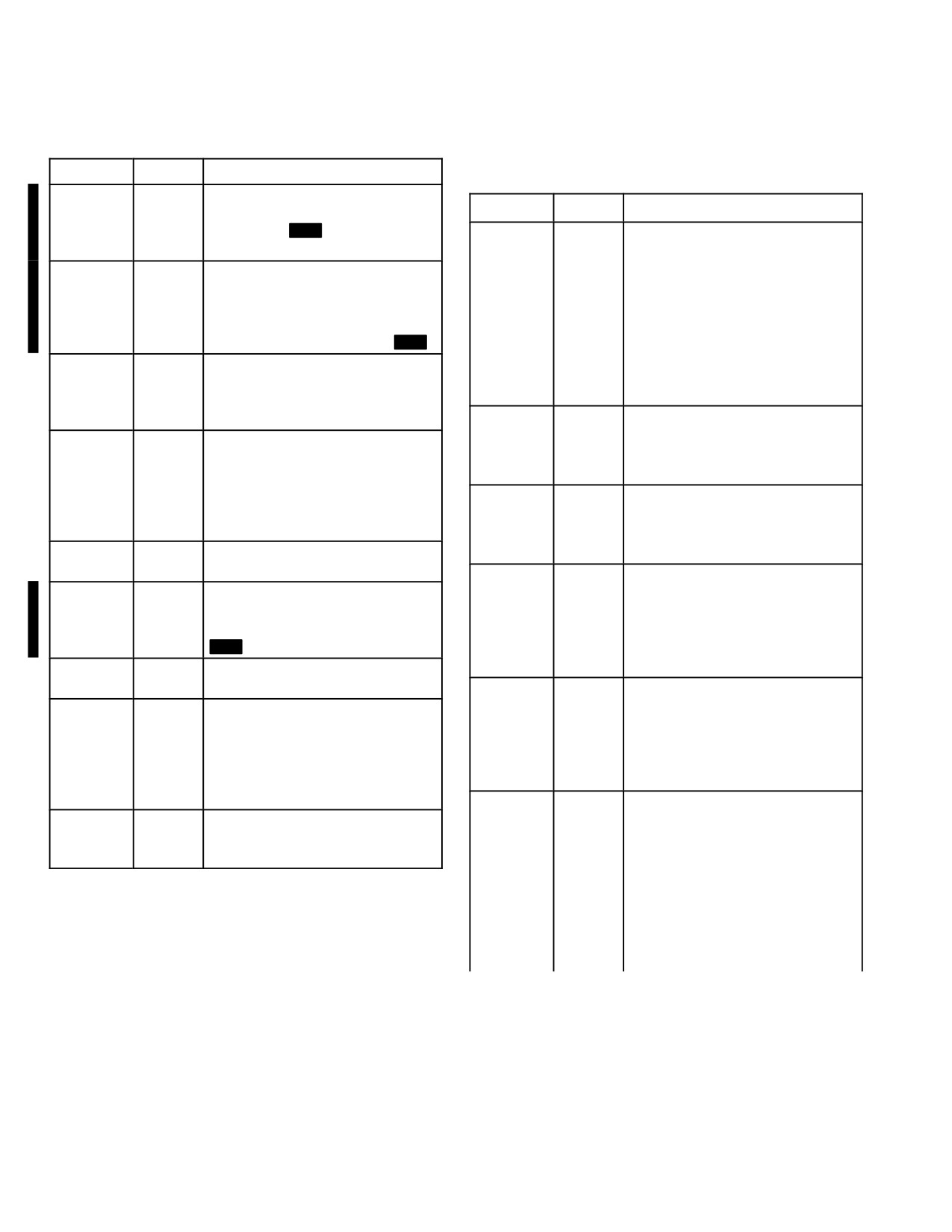
4.16.2 Range and Range Source Status Field. The
will increase or decrease based
HAD range and range source field (table 4-2) is located on
on helicopter movement or posi-
the top left of the display field and occupies five character
tion changes. Range displayed
spaces. This field provides range and range source mes-
is in km, maximum value is 32
sages based on the crew station.
km.
Use or disclosure of this information is subject to the restriction(s) on the title page of this document.
4-20
Change 4
TM 1-1520-251-10
Table 4-2. HAD Range and Range Source Status
Table
4-4. Weapon Status Field Messages
Field Messages (cont)
Message
Color
Description
Message
Color
Description
2 CHAN
Indicates priority and alternate
TRACK
channels are tracking.
RX.X
The weapon processor is using
radar range as a result of em-
ALT
Indicates alternate channel is
ploying the FCR in the pilot sta-
CHAN
tracking.
tion. Range is displayed in km,
TRK
maximum value is 9.9 km.
ALT
White
Indicates selected code for alter-
?
White
?An error has occurred. An illog-
CODE ?
nate channel is unusable. This is
ical and invalid condition has
due to the lack of PIM Code/
been identified.
Keyword correlation or the SAL
SEL is AUTO, the selected code
4.16.3 Weapon Control Status Field. The HAD weap-
is PIM and no SAL 2 missiles
on control status field (table 4-3) is located on the top right
are available but SAL 1 missiles
of the display field and occupies 5 character spaces. This
are available. Only displayed in
field provides the status of the selected weapon in the op-
ripple mode.
posite crew station.
DIR MAN
HF Missile trajectory is set to
DIR and missile MODE is set to
Table 4-3. Weapon Control Status Field Messages
MAN.
DIR
HF Missile trajectory is set to
Message
Color
Description
NORM
DIR and missile MODE is set to
NORM.
CGUN
CPG has actioned GUN system.
DIR RIPL
HF Missile trajectory is set to
CMSL
CPG has actioned Missile sys-
DIR and missile MODE is set to
tem.
RIPL.
COOP
Both PILOT and CPG have ac-
FIRE
The minimum interval between
tioned the Rocket system.
MSLS
launches has elapsed in a rapid
CRKT
CPG has actioned Rocket sys-
fire HF missile engagement, and
tem.
more than one missile is present
PGUN
PILOT has actioned Gun sys-
in priority channel after launch of
tem.
a missile.
PMSL
PILOT has actioned Missile sys-
GUN B/S
White
The gun has not been bore-
tem.
sighted or failed the boresight
verification. The gun will function
PRKT
PILOT has actioned Rocket sys-
normally but without boresight
tem.
corrections.
?
White
An error has occurred. An illogi-
GUN
White
The gun system has been ac-
cal and invalid condition has
FAIL
tioned but has been detected as
been identified.
NO - GO. Recycle the GUN Sys-
4.16.4 Weapon Status Field. The HAD weapon status
tem- ON/OFF power button. If
field (table 4-4) is located on the bottom right of the display
the fault message clears, contin-
ue operation.
field and occupies 12 character spaces. This field pro-
vides weapon status messages based on the selected
GUN JAM
White
The gun has been detected as
weapon system.
jammed.
Use or disclosure of this information is subject to the restriction(s) on the title page of this document.
Change 4
4-21
TM 1-1520-251-10
Table 4 - 4. Weapon Status Field Messages (cont)
Table 4 - 4. Weapon Status Field Messages (cont)
Message
Color
Description
Message
Color
Description
HANG-
Yellow
The fire signal was sent but um-
LOBL
Missile TRAJ is set to LOBL and
FIRE
bilical separation did not occur.
NORM
missile MODE is set to NORM.
This message is displayed for 6
LOBL
Missile trajectory is set to LOBL
seconds, during which time all
RIPL
and missile MODE is set to
HF missiles on that side of the
RIPL.
helicopter become “not avail-
able” and are inhibited from fir-
MISFIRE
Yellow
Indicates a HF misfire has oc-
ing.
curred. The fire signal was sent
but umbilical separation did not
HF
Indicates time (in seconds) until
occur at the predicted time. This
TOF=NN
missile impact. If more than one
message is displayed for 2 se-
missile is in flight, the display will
conds.
show TOF for the missile first
launched, then the subsequently
MSL
Indicates launch commanded in
launched missiles.
LAUNCH
the tactical mode. This message
is displayed for 2 seconds.
HI MAN
Missile trajectory is set to HI and
missile MODE is set to MAN.
MSL SE-
Missiles have been actioned, but
LECT
no primary channel has been
HI NORM
Missile trajectory is set to HI and
selected.
missile MODE is set to NORM.
HI RIPL
Missile trajectory is set to HI and
MSL
White
Indicates no missiles of the se-
missile MODE is set to RIPL.
TYPE?
lected type (RF or SAL) are
available.
LASE NN
The message is displayed for 4
TRGT
seconds starting at TOF =12
NO AC-
White
Indicates the RF missile has
calculated missile time of flight
QUIRE
completed its attempts to ac-
during LOAL launches.
quire the target and has re-
turned to ready mode.
LIMITS
White
Indicates pylons commanded to
elevation limit.
NO MIS-
White
Indicates no missiles (RF or
SILES
SAL) are available.
LO MAN
Missile trajectory is set to LO
and missile MODE is set to
NO
White
Indicates available rocket quan-
MAN.
ROCK-
tity is 0.
ETS
LO
Missile trajectory is set to LO
NORM
and missile MODE is set to
PRI
Indicates priority channel is
NORM.
CHAN
tracking.
TRK
LO RIPL
Missile trajectory is set to LO
and missile MODE is set to
PRI
White
Indicates selected code for the
RIPL.
CODE ?
priority channel is unusable.
This is due to lack of PIM Code/
LOAL
RF missile trajectory is defaulted
Keyword correlation or the SAL
MAN
to LOAL and missile MODE is
SEL is AUTO, the selected code
set to MAN.
is PIM and no SAL 2 missiles
are available but SAL 1 missiles
LOAL
RF missile trajectory is defaulted
are available.
NORM
to LOAL and missile MODE is
set to NORM.
DEF
Indicates the selected lethal
SCHEME
ranges in use is the default data
LOBL
Indicates LOBL INHIBIT mode is
X
(within FCR) and the selected
INHIBIT
selected.
priority scheme (A - G) for the
LOBL
Missile trajectory is set to LOBL
FCR. This message is only giv-
MAN
and missile MODE is set to
en when no weapon is actioned
MAN.
and FCR is the selected sight.
Use or disclosure of this information is subject to the restriction(s) on the title page of this document.
4-22
Change 4
TM 1-1520-251-10
Table 4 - 4. Weapon Status Field Messages (cont)
Table 4-5. HAD Weapon Inhibit Status Field
Messages
Message
Color
Description
MOD
Indicates selected lethal ranges
Generic Inhibits
SCHEME
in use is the modified data (from
X
the DTC) and the selected prior-
ALL
White
Displayed for 4 seconds to indi-
ity scheme (A - G) for the FCR.
TRKS
cate all TADS target tracks have
This message is only given
DEL
been deleted by the CPG
MT
when no weapon is actioned
LIVE
Yellow
Indicates live ammunition has
and FCR is the selected sight.
AMMO
been detected (or gun round en-
PYLON
White
Weapon has not been bore-
tered in rounds counter) when
B/S
sighted or failed the boresight
powering up a TESS missile.
verification. Subsystems will
Safety inhibit.
function normally but without py-
TRK X
White
Displayed for 4 seconds to indi-
lon CBHK corrections.
DEL
cate TADS target track number
RF MSL
Indicates an RF missile is track-
X has been deleted by the CPG
TRACK
ing.
MT
RKT
Indicates time (in seconds) until
TRK X
White
Displayed for 4 seconds to indi-
TOF=NN
rocket impact. If more than one
DROP
cate TADS target track number
volley is in flight, the display will
X has been dropped by the
show TOF for the last volley
MT
tracker
launched.
?
White
An error has occurred. An illogi-
ROUNDS
The gun system has been ac-
cal and invalid condition has
NNNN
tioned and the NNNN indicates
been identified.
the number of rounds remaining
and will count down one unit for
Message
Color
Description
each firing PULSE.
HELLFIRE Inhibits
SAL
White
Indicates the selected SAL mis-
ACCEL
White
Indicates the vertical accelera-
SEL?
sile type is unavailable. Only dis-
LIMIT
tion is less than or equal to .5
played in SAL1 or SAL2 SAL
Gs and may cause the main ro-
SELECT modes.
tor blades to obstruct the trajec-
SIM
Indicates launch commanded in
tory of the weapon. Safety inhib-
LAUNCH
the training mode. This mes-
it.
sage is displayed for 2 seconds.
ALT
White
Indicates an alternate launch is
TYPE?
White
Indicates no rocket type se-
LAUNCH
in progress. Safety inhibit.
lected.
BACK-
White
Indicates, based on Missile
WEAP-
White
The weapons trigger has been
SCAT-
Seeker vs TADS LOS, the seek-
ON?
pulled without a weapon being
TER
er is not tracking the TADS La-
actioned.
ser designation. Safety inhibit.
?
White
An error has occurred. An illogi-
BAL LIM-
White
Indicates range or other en-
cal and invalid condition has
IT
gagement parameters exceed
been identified.
the ballistics processing capabil-
ity of the system.
4.16.5 Weapon Inhibit Status Field. The HAD weap-
on inhibit field (table 4-5) is located in the center area of
the display field just above the Sensor FOR box and occu-
pies 12 character spaces. This field provides an indication
of safety or performance inhibit messages based on the
selected weapon system.
Use or disclosure of this information is subject to the restriction(s) on the title page of this document.
Change 4
4-23

TM 1-1520-251-10
Table 4-5. HAD Weapon Inhibit Status Field
Table 4-5. HAD Weapon Inhibit Status Field
Messages (cont)
Messages (cont)
HELLFIRE Inhibits (cont)
Message
Color
Description
Message
Color
Description
HELLFIRE Inhibits (cont)
PYLON
White
Indicates that the commanded
DATA IN-
White
This weapon has been actioned,
LIMIT
pylon position exceed the pylon
VALID
the FCR has been selected as
articulation limits (+4° to - 5° on
the active sight and the RF
ground) (+4° to - 15° in air). Per-
handover data recently received
formance or safety inhibit de-
has been detected as outside
pendent on air/ground status.
the navigational performance
parameters for weapons en-
RATE
White
Indicates the aircraft pitch, roll or
gagement. Safety inhibit.
LIMIT
yaw rate or acceleration is ex-
cessive. Performance inhibit.
GUN
White
Indicates the missiles resident
ROLL
White
Indicates the aircraft roll position
OB-
on inboard launchers are inhib-
LIMIT
is excessive. Performance inhib-
STRUCT
ited from launch because the
it.
gun is out of coincidence and
may obstruct the trajectory of
SKR LIM-
White
Indicates the missile seeker azi-
the missile. Safety inhibit.
IT
muth or elevation gimbal limit
has been reached. Performance
LASER
White
The ST/UPDT switch on the
inhibit.
RANGE?
LHG has been selected to the
UPDT position and the current
TRAIN-
White
Indicates the weapon training
range source is other than laser.
ING
mode is active, or the TESS is
enabled, and the armament con-
LOS
White
Indicates the selected LOS is ei-
trol is in the ARM state and a
INVALID
ther failed or invalid. Selection of
weapon is actioned in either
HMD as the sight when HMD
crew station.
symbology belongs to the alter-
nate crewmember will also gen-
TXX
White
Displayed for 4 seconds to indi-
erate this inhibit. This condition
cate file address in which the
can occur either when the CPG
coordinate data has been stored
selects presentation of the pilot
(TADS/FCR target store switch
information using the ORT VID
on LHG).
SEL select or TEDAC PNV
YAW
White
Indicates yaw position of the air-
switch, and can also occur dur-
LIMIT
craft with respect to the target is
ing single display processor op-
excessive. Applies to LOAL
erations. Safety inhibit.
mode only. Performance inhibit.
MSL NOT
White
No HF missiles are ready for
GUN Inhibits
RDY
launch: no SAL missile priority
channel selected or RF missile
ALT
White
Indicates a Rocket or Hellfire
transfer alignment not complete.
LAUNCH
launch is in progress. Safety in-
hibit.
PYLON
White
Indicates the pylon position is u
AZ
White
Indicates the gun is positioned
ANGLE
10 ° from the optimum launch
LIMIT
at an azimuth limit. Safety inhib-
position or that pylon position is
it.
unknown. Performance inhibit.
BAL
White
Indicates range or other en-
PYLON
White
Indicates the aircraft is on the
LIMIT
gagement parameters exceed
ERROR
ground and the pylons position
the ballistics processing capabil-
is unknown or that the pylons
ity of the system.
are positioned such that the mis-
sile may strike the ground near
COINCI-
White
Indicates the gun is currently out
the aircraft. Safety inhibit.
DENCE
of coincidence. Safety inhibit.
Use or disclosure of this information is subject to the restriction(s) on the title page of this document.
4-24
Change 4
TM 1-1520-251-10
Table
4-5. HAD Weapon Inhibit Status Field
Table 4-5. HAD Weapon Inhibit Status Field
Messages (cont)
Messages (cont)
ROCKET Inhibits (cont)
Message
Color
Description
PYLON
White
Indicates that the commanded
LIMIT
pylon position exceed the pylon
GUN Inhibits (cont)
articulation limits (+4° to - 5° on
ground) (+4° to - 15° in air). Per-
EL
White
Indicates the gun is positioned
formance or safety inhibit de-
LIMIT
at an elevation limit. Safety in-
pendent on air/ground status.
hibit.
SAFE
White
Indicates the weapon system
LOS
White
Indicates the selected LOS is ei-
has not been ARMed through
INVALID
ther failed or invalid. Safety in-
the ARMAMENT control panel.
hibit.
TRAIN-
White
Indicates the weapon training
SAFE
White
Indicates the weapon system
ING
mode is active, or the TESS is
has not been ARMed through
enabled, and the armament con-
the ARMAMENT control panel.
trol is in the ARM state and a
weapon is actioned in either
TRAIN-
White
Indicates the weapon training
crew station.
ING
mode is active, or the TESS is
TXX
White
Displayed for 4 seconds to indi-
enabled, and the armament con-
cate the file address in which the
trol is in the ARM state and a
coordinate data has been
weapon is actioned in either
stored.
crew station.
TYPE
White
Indicates that no rocket type is
TXX
White
Displayed for 4 seconds to indi-
SELECT
selected. Safety inhibit.
cate the file address in which the
coordinate data has been
4.16.6 Sight Select Status Field. The HAD sight se-
stored.
lect status field (table 4-6) is located on the top left of the
display field and occupies 5 character spaces. This field
ROCKET Inhibits
provides status of the state of the selected sight in that
station. The LINK status
displays when the FCR and
ACCEL
White
Indicates that the vertical accel-
TADS are operating in a linked mode.
LIMIT
eration is less than .5 G’s and
may cause the main rotor
Table 4-6. HAD Sight Select Status Field Messages
blades to obstruct the trajectory
of the rockets. Safety inhibit.
Message
Color
Description
ALT
White
Indicates that a Hellfire launch is
P-FCR/
White
The PLT or CPG has selected
LAUNCH
in progress. Safety inhibit.
C-FCR
FCR as the active LOS.
GUN
White
Indicates the rockets resident on
P-FCRL/
White
FCR is the selected sight and
OB-
inboard launchers are inhibited
C-FCRL
TADS is linked to the FCR NTS.
STRUCT
from launch because the gun is
If a missile is tracking, TADS is
out of coincidence and may ob-
linked to the missile LOS.
struct the trajectory of the rock-
P-HMD/
White
The PLT or CPG has selected
ets. Safety inhibit.
C-HMD
HMD as the active LOS.
LOS
White
Indicates that the selected LOS
TADS
White
The CPG has selected TADS as
INVALID
is either failed or invalid. Safety
the active LOS.
inhibit.
TADSL
White
TADS is the selected sight and
FCR is linked to the TADS.
PYLON
White
Indicates that the pylon eleva-
ERROR
tion position is not equal to the
?
White
An error has occurred. An illogi-
commanded pylon position.
cal and invalid condition has
Safety inhibit.
been identified.
Use or disclosure of this information is subject to the restriction(s) on the title page of this document.
Change 3
4-25
TM 1-1520-251-10
4.16.7 HMD FORMAT OWNER CUE. During single DP
EOCCM filters and growth provisions for an image intensi-
operations, the HMD FORMAT OWNER CUE will read
fication system to compliment the FLIR. This system per-
PLT FORMAT or CPG FORMAT. This will flash for 3 sec-
mits the pilot to fly nap-of-the-earth (NOE), and enhances
onds whenever the ownership changes, and upon entry/
navigation at night or in limited adverse weather. The
exit into single DP operations. Refer to paragraph 4.50.3.
PNVS provides the pilot or CPG with a high resolution
FLIR video.
4.16.8 Acquisition Select Status Field. The HAD ac-
4.18 PNVS OPERATION
quisition select status field (table 4-7) is located on the top
right of the display field and occupies 4 character spaces.
When NVS NORM is selected, the turret is slaved to the
This field provides status of the selected acquisition
helmet LOS. During normal operations, the pilot has con-
source in that crew station.
trol of the PNVS turret. However, if the pilot becomes inca-
pacitated, the CPG may take control of the PNVS.
4.18A [
MT
FLIR SCENE ASSISTED
Table 4-7.
HAD Acquisition Status Field Messages
NON - UNIFORMITY CORRECTION (SANUC)
Message
Color
Description
The SANUC process is performed in order to assure full
convergence of the NUC coefficients to fully optimize
FCR
The operator has selected FCR
FLIR image quality for PNVS and TADS.
as the acquisition source.
FXD
The operator has selected FXD
Standard Process Initialization
as the acquisition source.
• The standard SANUC process will be automatical-
GHS
The operator has selected GHS
ly performed following FLIR cool - down. No imag-
as the acquisition source.
ery will be displayed during cool - down and
PHS
The operator has selected PHS
SANUC. Once the SANUC is completed (approxi-
as the acquisition source.
mately 14 seconds). FLIR imagery will be dis-
RFI
The operator has selected RFI
played and the sensor will become available for
as the acquisition source.
use.
SKR
The operator has selected SKR
• During SANUC, the optics are defocused to
as the acquisition source.
remove high frequency scene content and SA-
TADS
The operator has selected TADS
NUC thresholds are opened up to allow rapid
as the acquisition source.
update of both gain and level coefficients.
For PNVS, this operation requires the gimbal to
TXX, or
The operator has selected TXX,
move to fixed forward and dither in elevation for
CXX, or
CXX, WXX, or HXX as the ac-
several seconds so that the FLIR sensor sees a
WXX, or
quisition source.
variety of temperatures in the scene.
HXX
For TADS, the turret will move to fixed forward and
TRN
The operator has selected Ter-
dither in elevation for several seconds.
rain Point as the acquisition.
• If the turret is in use with a TV sensor when FLIR
?
White
An error has occurred. An illogi-
cool - down is complete, SANUC will not be
cal and invalid condition has
performed until FLIR is selected as the sensor.
been identified.
One - Touch Process Initialization
4.17 PNVS DESCRIPTION
•
The one- touch SANUC process will be performed
for FLIR power - up in the air. It will take approxi-
NOTE
mately one second to perform a single point
correction at the scene temperature when FLIR
If using EXT PWR TADS/PNVS will not pow-
cool - down is complete. No imagery will be dis-
er up automatically.
played during cool - down, however, imagery will
be available during the one - touch and the opaque
The PNVS consists of a FLIR sensor contained in a stabi-
filter will be visible. The opaque filter is used as the
lized rotating turret mounted above the TADS. The aircraft
single reference for the one - touch, which corrects
may be equipped with legacy PNVS or Modernized PNVS
for offset errors, but not gain or quadratic coeffi-
(MPNVS) which includes an improved FLIR sensor with
cient errors.
Use or disclosure of this information is subject to the restriction(s) on the title page of this document.
4-26
Change 4
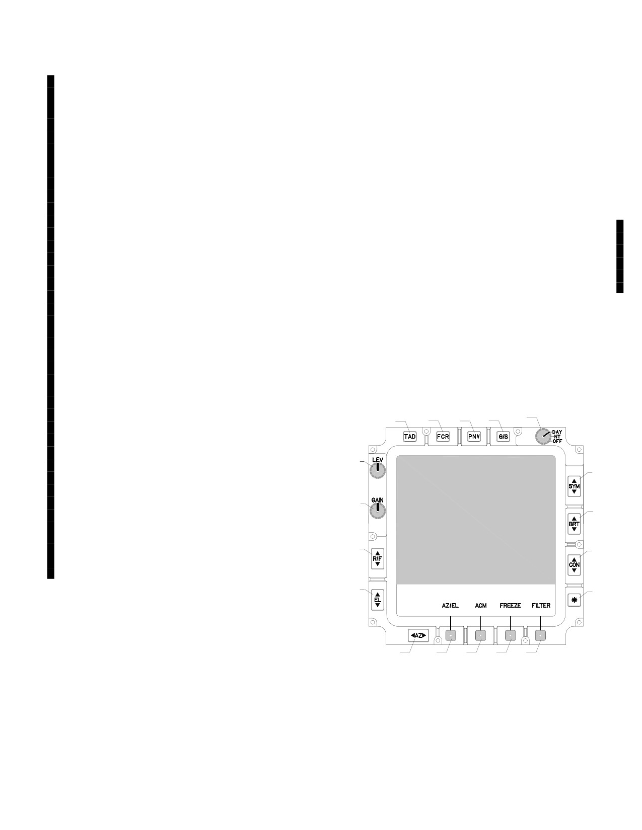
TM 1-1520-251-10
The SANUC process is performed under the following cir-
4.20 TADS DESCRIPTION
cumstances:
NOTE
• For normal ground initialization, the standard
If using EXT PWR TADS/PNVS will not pow-
SANUC initialization process that involves gimbal
er up automatically.
slewing remains for normal TADS FLIR power - up
on the ground.
The TADS assembly is an Electro-Optical system that
uses direct view optics (DVO)(ORT only), a day television
• For rapid/emergency departure/power interrup-
(DTV) sensor, a laser spot tracker (LST), a laser range-
tions/in - flight initialization, a quick one - touch
finder/ designator (LRF/D), and a forward looking infrared
procedure is implemented for use while the aircraft
(FLIR) sensor for day, night, and limited adverse weather
is in the air. The weight - on - wheels signal being
operations. The aircraft may be equipped with legacy
sent form the aircraft to the M - TEU or M - PEU is
TADS or Modernized TADS (MTADS) which includes an
used to determine which procedure will be per-
improved FLIR sensor and, in addition to the components
formed.
listed above, automated internal boresight, EOCCM fil-
The SANUC coefficients change during operation
ters, a multi - target tracker and growth provisions for an
to remove residual fixed pattern noise and are able
extended range (XR) zoom FOV.
to pull the image in over the next few minutes.
During the remainder of the flight, additional
4.20A TADS ELECTRONIC DISPLAY AND CONTROL
one - touch updates are performed.
(TEDAC) CONTROLS
• For IBIT, a commanded SANUC update is inte-
The TEDAC bezel panel (fig 4-27A) provides access to
grated into the IBIT process (for ground testing).
the controls necessary to adjust video on the TEDAC Dis-
Also, a commanded one - touch update is inte-
play Unit (TDU) and the CPG HMD.
grated into the IBIT process (for flight testing).
• For TADS internal boresight, in the case of the
TADS FLIR, a one - touch is used to perform a
1a.
1b.
1c.
1d.
2
near - term SANUC coefficient update for bore-
sighting.
Typical in - flight boresight is performed twice per
flight. Integrating an additional one - touch update
3
7
into the beginning of the internal boresight process
provides the best - compensated image prior to
delivering weapons. This is an automatic step in
4
8
the boresight process and is performed during the
gimbal slew time.
• For standby (turret in stow), one touch update is
5
9
performed upon exit. This is a quick, easy method
to recalibrate the image.
6
10
4.19
PNVS ANTI-ICE
11
12
13
14
15
LBA5501
When the pilot or CPG selects anti-ice using the aircraft
UTIL page ANTI-ICE SENSOR button and the helicopter
Figure 4-27A. TEDAC Controls
is off the ground, 115 Vac is applied to the PNVS shroud
window and a shroud frame heater. When the anti-ice is
turned on (automatically or manually) and the aircraft is in
1. Video Select Buttons. These bezel pushbuttons
the air, power is applied to the PNVS window and shroud
select the video source to be displayed to the CPG on the
frame heaters. PNVS anti-ice can be selected when the
TDU. The default video upon initialization is based on the
aircraft is on the ground by using the GND button.
default sight selection of HMD (flight format, no video).
Use or disclosure of this information is subject to the restriction(s) on the title page of this document.
Change 4
4-26.1
TM 1-1520-251-10
Subsequently selecting one of these pushbuttons will pro-
NOTE
vide the selected video.
Symbol Brightness (SYM), Display Bright-
ness (BRT) and Display Contrast (CON)
a. TAD. The TAD pushbutton selects TADS as the
rocker switches operate in three different
video source.
modes:
Step Input - Momentarily pressing and re-
leasing the switch will cause a single step
b. FCR. The FCR pushbutton selects the FCR tar-
change.
geting format to be displayed.
Slow Rate Input - Pressing and holding the
switch for 1/2 second will cause change
c. PNV. The PNV pushbutton selects PNVS as the
continually at the slow rate.
video source.
Fast Rate Input - Pressing and holding the
switch for more than one second will cause
d. G/S. The G/S pushbutton activates the grayscale for
change continually at a fast rate.
the video display. The G/S format will completely fill the dis-
play area and the bottom bezel button labels will be removed.
7. Symbol Brightness. The SYM switch adjusts
the intensity of the TADS LOS reticle, IAT gates and FCR
2. Day/Night/Off Mode. The DAY/NT/OFF control
targeting format symbology brightness. The adjustment
knob selects the TEDAC day, night and off modes of op-
varies form black to white.
eration.
8. Display Brightness. The display BRT switch ad-
justs the grayscale and/or image brightness intensity.
a. DAY. The day mode provides a brighter day
mode luminance with a white backlight color. Video ap-
9. Display Contrast. The CON switch adjusts the
pears as shades of gray.
grayscale and/or image contrast intensity.
10. Asterisk (*) Button. The (*) pushbutton adjusts the
b. NT. The night mode extinguishes the backlight
brightness and contrast to nominal settings to rapidly regain
brightness and provides a lower night mode luminance
visibility of the selected video. The settings are unique to the
with a green NVG compatible backlight. Video appears as
day or night selection of the DAY/NT/OFF control.
shades of green.
11. Azimuth Adjust. The AZ adjust switch is used
c. OFF. The off position extinguishes all iluminating
for various boresight adjustments. It is active only when
backlight even though the video is routed to the TDU.
the AZ/EL boresight enable pushbutton is selected.
12. AZ/EL Boresight Enable. The AZ/EL boresight
enable button is used to enable boresight controls. Select-
3. FLIR Level. The FLIR LEV control adjusts FLIR
ing the pushbutton will cause the AZ/EL label to become
level for the TADS or PNVS FLIR imagery as selected at
boxed and enable the EL and AZ bezel switches for vari-
the NVS select switch.
ous boresight adjustments.
13. Automatic Contrast Mode (ACM). The ACM
4. FLIR Gain. The FLIR GAIN control adjusts FLIR
button is used to activate the ACM. Selecting the ACM
gain for the TADS or PNVS FLIR imagery as selected at
pushbutton will cause the ACM label to become boxed
the NVS select switch.
and activate the ACM. In this mode, FLIR LEV and GAIN
controls are disabled and FLIR gain and level are auto-
matically adjusted to compensate for scene thermal con-
5. Range Focus. The R/F switch adjusts video fo-
tent changes and switching polarities.
cus in DTV or FLIR video. The minimum distance that may
NOTE
be focused is 500m for FLIR NFOV or MFOV; 1500m for
DTV NFOV.
All other switches/pushbuttons on the TE-
DAC bezel remain active when the display is
in a FREEZE state. Any inputs/adjustments
6. Elevation Adjust. The EL adjust switch is used
made when the display is in this state will
for various boresight adjustments. It is active only when
become visible when the FREEZE button is
the AZ/EL boresight enable button is selected.
deselected.
Use or disclosure of this information is subject to the restriction(s) on the title page of this document.
4-26.2
Change 4
TM 1-1520-251-10
14. Display Freeze. The FREEZE button is used to
protection. Selecting the FILTER pushbutton will cause the
freeze the video imaging on the TDU. Selecting the
FILTER label to become boxed when Filter 1 or 2 is selected.
FREEZE button will cause the FREEZE label to become
Selections are set sequentially to Filter 1, Clear, Filter 2,
boxed and freeze the currently selected video. The video
Clear, Filter 1, etc. The selected state is reflected in the se-
image may be returned to normal by deselecting the
lected sensor status on the weapon format on the TDU/
FREEZE button or by selecting another video source.
HMD The filter should be inserted when a circular type
pattern containing saturated pixels and encompassing
15. Sensor Filter. The FILTER button is used to select
approximately 1/5 the FOV is observed. A reduced size in
between the two spectral filters in the TADS FLIR sensor. The
the circular type pattern will result.]
FLIR filters are used as countermeasures protection. Select-
ing the FILTER pushbutton will cause the FILTER label to be-
16. TEDAC Display Unit (TDU). The TDU is used
come boxed and set the FLIR filter to maximum. The filter
for viewing images generated by the TADS DTV or FLIR,
may be returned to clear by deselecting the FILTER button.
FCR
or VCR. It is an active matrix liquid crystal display
The TADS FLIR filter is functional only on aircraft equipped
(AMLCD) with a viewable area 5 inches square. Video im-
with the Optically Improved (OI) TADS.
agery is presented in a 4x3 aspect display area in the up-
[
MT
The FILTER button is used to select between the
per portion of the viewable area. Control labels for the AZ/
three spectral filters in the TADS FLIR sensor: Clear, Filter 1,
EL, ACM, FREEZE, and FILTER buttons are displayed in
and Filter 2. The FLIR filters are used as countermeasures
the lower portion of the viewable area.
Use or disclosure of this information is subject to the restriction(s) on the title page of this document.
Change 4
4-26.3/(4-26.4 blank)
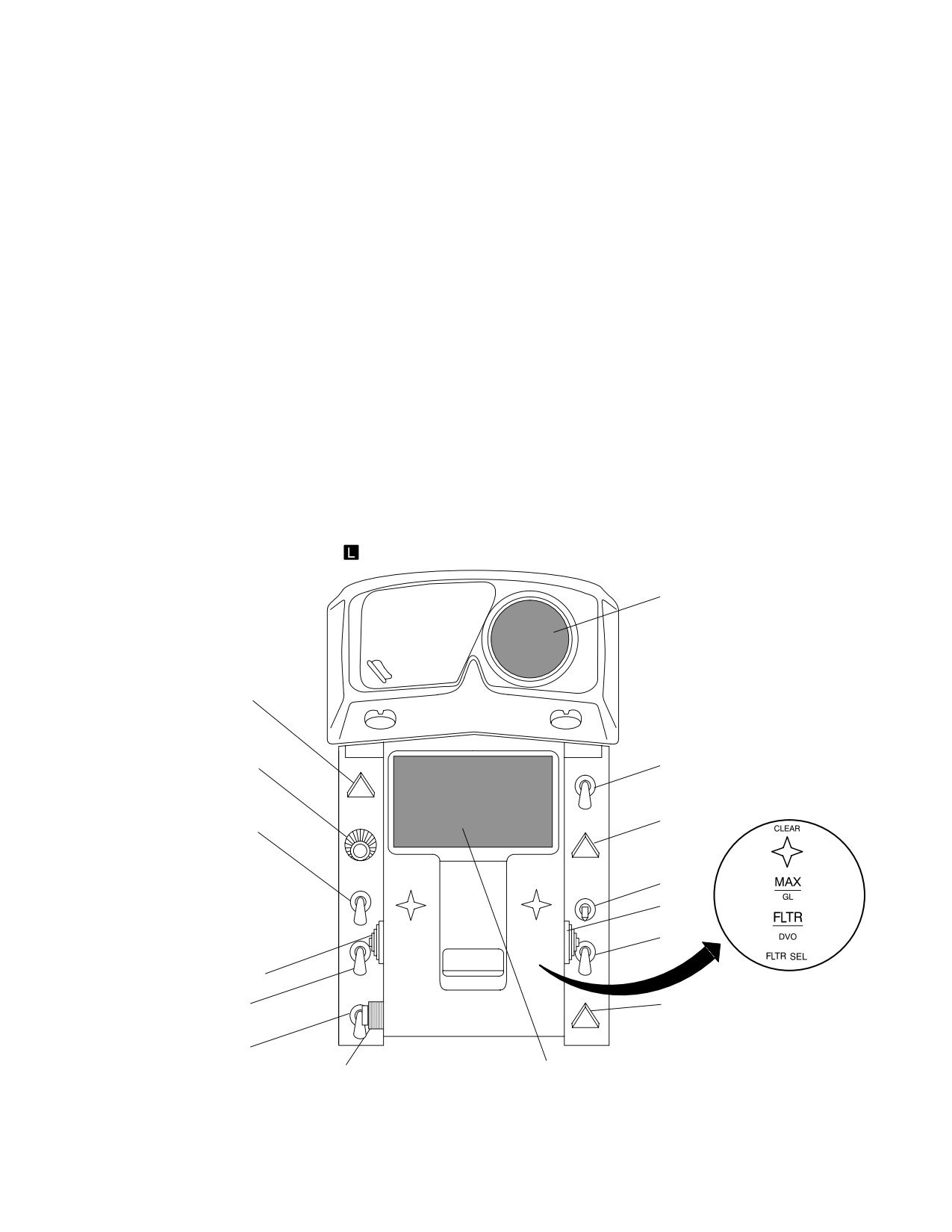
TM 1-1520-251-10
4.21 OPTICAL RELAY TUBE (ORT) CONTROLS
5. Grayscale. The GS switch activates the grays-
cale for the ORT HOD or HDD video displays. The grays-
The ORT control panel (fig 4-28) provides access to the
cale is displayed on these displays based on the selection
controls necessary to adjust video on the HOD/HDD and
of the HDD switch located on the ORT RHG.
the CPG HMD. The adjustable faceplate includes an opti-
cal eyepiece with adjustable focus.
6. Visor Retract. Inactive.
1. FLIR Level. The FLIR LVL control is used to ad-
7. Night Mode. The NT switch activates the night
just FLIR level for the TADS or PNVS FLIR imagery as se-
filter. Momentarily pressing the NT pushbutton switch
lected at the NVS select switch.
toggles the red night filter for the HDD.
2. FLIR Gain. The FLIR GAIN control adjusts FLIR
gain for the TADS or PNVS FLIR imagery as selected at
8. Automatic Contrast Mode (ACM). The ACM
the NVS select switch.
control provides automatic FLIR gain and level control.
The ACM position disables the FLIR gain and level con-
trols and automatically adjusts FLIR gain and level control
3. Range Focus. The RNG FOC switch adjusts vid-
to compensate for scene thermal content changes and
eo focus in DTV or FLIR video. The minimum distance
switching polarities. The down position (no label) disables
that may be focused is 500m for FLIR NFOV or MFOV;
ACM and enables the FLIR GAIN and FLIR LVL knobs.
1500m for DTV NFOV.
4. Video Select. The VID SEL switch selects the
9. Symbol Brightness. The SYM BRT control ad-
video source to be displayed to the CPG on the ORT
justs the intensity of the ORT format, TADS LOS reticle,
HOD/HDD. Placing the switch to one of three positions will
and IAT gate symbology brightness. The adjustment va-
select the video source: TADS, FCR
, or PNVS.
ries from black to white.
15
1
2
LVL
8
ACM
9
GAIN
3
SYM
BRT
TADS
10
RNG
CLEAR
G
BRT
F
H
H
L
11
C
A
A
A
R
Z
Z
PNVS
R
FOC
E
GLARE
E
E
DSPL
12
GS
VID
FLTR
SEL
SEL
4
CONT
FLTR SEL SWITCH FOR
V/RET
AND
OPTICALLY IMPROVED TADS
5
13
NT
BRT
6
7
14
LBA1021
Figure 4-28. ORT Control Panel
Use or disclosure of this information is subject to the restriction(s) on the title page of this document.
4-27
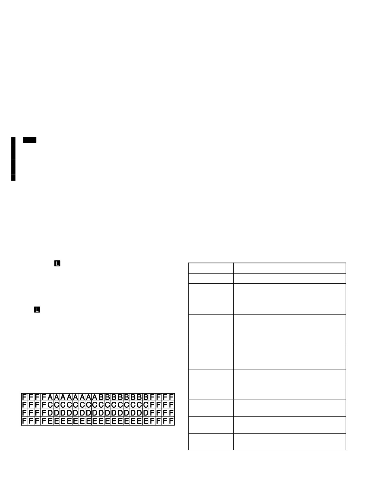
TM 1-1520-251-10
10. Display Brightness. The display BRT control
The status fields (sections) displayed in the AND are:
adjusts the grayscale and/or image brightness intensity.
a. Sight Status Field.
11. Filter Select. The FLTR SEL switch located on
the right side of the ORT control panel selects a filter for
b. Weapon Status Field.
the DVO. Placing the switch to one of two positions will se-
lect the DVO filter: CLEAR, HAZE GLARE, GLARE, or
HAZE. In the Optically Improved (OI) TADS, filter selec-
c. Tracker Status Field.
tion can also be made when sensor select is FLIR. The
FLIR filters are used as countermeasures protection.
d. LRFD and LST Code Status Field.
There are two selections: CLEAR and MAX.
e. Enhancement Display Status Field.
[
MT
The FLTR SEL switch located on the right side of
the ORT control panel selects between the three spectral
f. Missile Inventory and Status Field.
filters in the TADS FLIR sensor: Clear, Filter 1, and Filter 2.
The FLIR filters are used as countermeasures protection.
The selected state is reflected in the selected sensor sta-
4.22.1
AND Messages. Messages will be centered
tus on the weapon format on the ORT/HMD.]
within the appropriate status field.
12. Display Contrast. The DSPL CONT control ad-
4.22.2 AND Sight Status Field. The AND sight status
justs the grayscale and/or image contrast intensity.
field is located on the top left of the display adjacent to the
left missile status and inventory field and occupies 8 char-
13. Alphanumeric Display (AND) Brightness. The
acter spaces. Messages and their definitions are con-
AND BRT control adjusts the brightness intensity of the
tained in table 4-8.
AND.
14. Head Out Display (HOD). The HOD is used for
Table 4-8. Sight Status Field Messages
viewing images generated by the DTV, TADS FLIR,
PNVS, FCR
, and VCR.
MESSAGE
DEFINITION
15. Head Down Display (HDD). The HDD is viewed
CSCOPE
C-scope has been turned ON.
through the faceplate eyepiece. It is used for direct view-
FLIRFAIL
FLIR has been detected as NO - GO.
ing of real world images through the DVO as well as view-
Night side capabilities are lost includ-
ing of images generated by the DTV, TADS FLIR, PNVS,
ing use of the TADS for NVS pilotage.
FCR
, and VCR. It is also used to view the AND status
CPG must use DVO or DTV.
messages.
IMPEND
The laser is approaching conditions
LASER
which will prohibit it from firing. The
4.22 ORT ALPHANUMERIC DISPLAY (AND)
INHIBIT
message alternates (IMPEND, then
LASER, then INHIBIT).
The alphanumeric display (AND) is located below the
LASER
The laser has been inhibited from fir-
head down display in the ORT. It consists of a light emit-
INHIBIT
ing. The message alternates (LASER,
ting diode array of 24 character spaces long and 4 spaces
then INHIBIT).
high (fig 4-29). The AND provides information to the CPG
LRFD
TADS LRF/D power is ON and the
for use in the operation of sight and weapons systems.
COOLANT
transceiver coolant level detected as
low. The message alternates (LRFD,
then COOLANT).
LSTCODE?
The selected LST laser code is not us-
able.
PLT TADS
The pilot controls the TADS as the
LBA2560
NVS sensor through LINK.
RFDCODE?
The selected LRFD laser code is not
Figure 4-29. Alphanumeric Display
usable.
Use or disclosure of this information is subject to the restriction(s) on the title page of this document.
4-28
Change 4
TM 1-1520-251-10
Table 4-8. Sight Status Field Messages (cont)
Table 4-9. Weapon Status Field Messages
(WAS =MSL) (cont)
MESSAGE
DEFINITION
DIR RIPL
Missile trajectory is direct; missile
TADSFAIL
TADS has been detected as NO - GO
mode is ripple.
and the TADS LOS defaults to fixed
FIRE
Minimum time between launch has
forward.
MISSILES
elapsed in rapid fire Hellfire missile
engagement, and one or more mis-
TADS NOT
TADS is selected and turret internal
siles are present in the PRI channel
READY
temperature has not reached operat-
after launch of a missile. The mes-
ing temperature. The message alter-
sage alternates (FIRE, then MIS-
nates (TADS NOT, then READY).
SILES).
TADSTEMP
TADS is selected and the turret inter-
HANGFIRE
Fire signal sent but umbilical separa-
nal temperature is detected as over-
heating.
tion did not occur at predicted time.
Message is displayed for 6 seconds,
TGT LOS
The LOS to the selected TXX acquisi-
during which time all missiles on that
INVALID
tion source is invalid. The message
side of the aircraft become “not avail-
alternates (TGT LOS, then INVALID).
able” and are inhibited from firing.
TV FAIL
TADS has been detected as NO - GO.
Replaces “MSL LNCH/TOF = NN”.
CPG must use DVO or FLIR.
HFTOF=NN
Indicates time (in seconds) until mis-
sile impact. If more than one missile
is in flight, displays TOF for first mis-
4.22.3 AND Weapon Status Field. The AND weapon
sile launched, then subsequent mis-
status field is located between the sight status field and
siles.
the right missile status and inventory field and occupies
HI NORM
Missile trajectory is high; missile
eight character spaces. Messages and their definitions
mode is normal.
are contained in tables 4-9 through 4-11.
HI RIPL
Missile trajectory is high; missile
mode is ripple.
HI MAN
Missile trajectory is high; missile
mode is manual.
Table 4-9.
Weapon Status Field Messages
LASE NN
Cue to lase target for terminal missile
(WAS = MSL)
TARGET
guidance. Displayed for 4 seconds
starting at TOF=12. Calculated TOF
in place of “TOF = NN” message is
MESSAGE
DEFINITION
displayed if actual trajectory is not
ALT CHAN
Alternate missile channel tracking.
LOBL. The message alternates
TRACK
The message alternates (ALT
(LASE NN, then TARGET).
CHAN, then TRACK).
LOAL MAN
Missile launch mode is LOAL; missile
mode is manual.
ALTCODE?
Indicates selected code for the alter-
nate channel is unusable. This is due
LOALNORM
Missile launch mode is LOAL; missile
to the lack of PIM Code/Keyword cor-
mode is normal.
relation or the SAL SEL is AUTO, the
LOBL INH
The LOBL inhibit mode is selected
selected code is PIM and no SAL 2
(RF missile launch).
missiles are available but SAL 1 mis-
siles are. Only displayed in ripple
LOBL MAN
Missile launch mode is LOBL; missile
mode.
mode is manual.
DIR MAN
Missile trajectory is direct; missile
LOBLNORM
Missile launch mode is LOBL; missile
mode is manual.
mode is normal.
DIR NORM
Missile trajectory is direct; missile
LOBLRIPL
Missile launch mode is LOBL; missile
mode is normal.
mode is ripple.
Use or disclosure of this information is subject to the restriction(s) on the title page of this document.
4-29
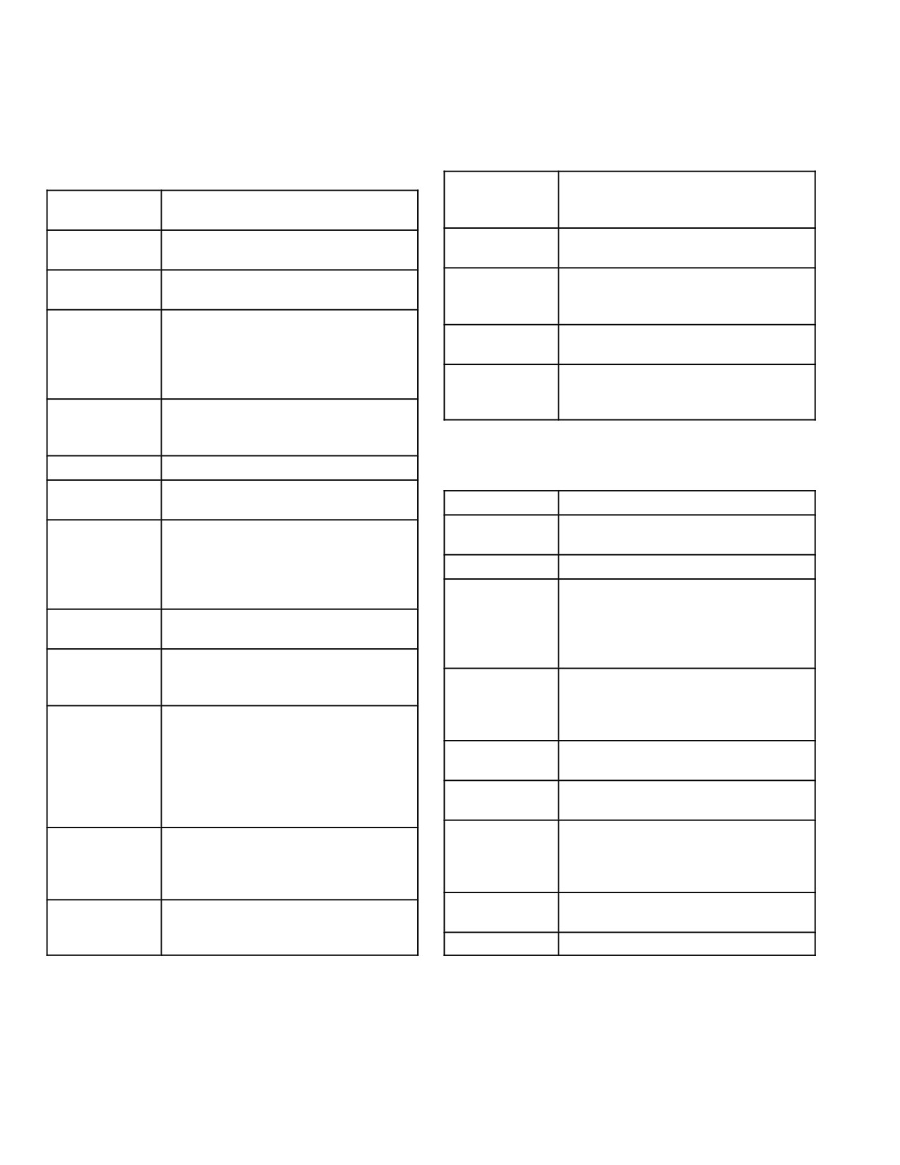
TM 1-1520-251-10
Table 4-9. Weapon Status Field Messages
Table 4-9. Weapon Status Field Messages
(WAS =MSL) (cont)
(WAS =MSL) (cont)
SAL SEL?
Indicates the selected SAL missile
LO MAN
Missile trajectory is low; missile mode
type is unavailable. Only displayed in
is manual.
SAL1 or SAL2 SAL SELECT modes.
LO NORM
Missile trajectory is low; missile mode
SIGHT?
Sight selected for HF missile launch
is normal.
is not valid or has failed.
LO RIPL
Missile trajectory is low; missile mode
SIM LNCH
Missile launch commanded in train-
is ripple.
ing mode. Message is displayed for 2
seconds.
MISFIRE
Indicates a HF misfire has occurred.
The HF launch sequence was initi-
TGTDATA?
No target data available for RF mis-
ated and aborted prior to missile
sile launch.
launch. This message is displayed
2CHAN...
Priority and alternate missile chan-
for 2 seconds.
TRACK
nels tracking. The message alter-
MSL LNCH
Missile launch commanded in tactical
nates (2CHAN, then TRACK).
mode. Message is displayed for 2 se-
conds.
Table 4-10.
Weapon Status Field Messages
MSL SEL
No priority channel selected.
(WAS=RKT)
MSLTYPE?
Indicates no missiles of the selected
MESSAGE
DEFINITION
type (RF or SAL) are available.
LIMITS
The wing pylons have articulated to
NO...
The RF missile has completed at-
the elevation limit.
ACQUIRE
tempts to acquire the target and has
returned to the standby mode. The
NO RKTS
The rocket quantity available is 0.
message shall alternate (NO, then
PYLON B/S
The pylons have not been bore-
ACQUIRE).
sighted or have failed the boresight
NO MSLS
Indicates missiles have been ac-
verification. Subsystems will function
tioned, but no RF missiles available.
normally but without pylon boresight
corrections.
PRI CHAN..
Priority missile channel tracking. The
TRACK
message alternates (PRI CHAN,
RKT BIT...
The rocket system components are
then TRACK).
INPROG
undergoing a power - on BIT. The
message alternates (RKT BIT, then
PRICODE?
Indicates selected code for the pri-
INPROG).
mary channels is unusable. This is
due to lack of PIM Code/Keyword
RKT G - S
The wing pylons are commanded to
correlation or the SAL SEL is AUTO,
ground stow.
the selected code is PIM and no SAL
RKT NORM
The rocket system is operating in the
2 missiles are available but SAL 1
normal articulation mode.
missiles are.
RTOF=NN
Indicates time (in seconds) until rock-
PYLN B/S
Pylons have not been boresighted, or
et impact. If more than one volley is
have failed boresight verification.
in flight, the display will show TOF for
Subsystems will function normally but
the volley last launched.
without pylon boresight corrections.
SIGHT?
The sight selected for rocket launch
RF MSL...
RF missile channel tracking. The
is not valid or it has failed.
TRACK
message alternates (RF MSL, then
TRACK).
TYPE?
No rocket warhead type is selected.
Use or disclosure of this information is subject to the restriction(s) on the title page of this document.
4-30
TM 1-1520-251-10
Table 4-11.
Weapon Status Field Messages
Table 4-12. AND Tracker Status Field (cont)
(WAS=GUN)
IAT BREAK-
The image auto tracker has broken
MESSAGE
DEFINITION
LOCK
track.
GUN B/S
The gun has not been boresighted or
IAT OFFSET
IAT offset tracking is engaged.
has failed the boresight verification.
IAT TRACK
IAT tracking is engaged and tracking.
The gun will function normally but
without pylon boresight corrections.
IAT B/W
IAT polarity is black on white.
GUN FAIL
The gun has been detected as failed.
IAT W/B
IAT polarity is white on black.
Recycle the GUN system - ON/OFF
IAT AUTO
IAT is in the automatic mode
POWER button. If the fault message
clears, continue operation.
4.22.5 AND LRFD and LST Code Status Field. The
GUN JAM
The gun has been detected as
AND LRFD and LST code status field is located directly
jammed.
below the tracker status field and occupies 16 character
spaces. Messages and their definitions are contained in
RDSNNNN
The gun system is operating in the
selected mode. The NNNN indicates
table 4-13.
the number of rounds remaining and
will count down in real time as the
Table 4-13. AND LRFD and LST Status Field
gun is fired.
SIGHT?
The sight selected for gun firing is not
MESSAGE
DEFINITION
valid or it has failed.
LRFD FIRST
The LRFD has been activated and
WEAPON?
The weapons trigger has been
the LRFD button is set to FIRST.
pressed with no weapon system ac-
LRFD LAST
The LRFD has been activated and
tioned.
the LRFD button is set to LAST.
CODELST=A
LRFD is not operational but the LST
4.22.4 AND Tracker Status Field. The AND tracker
is operational and the selected code
status field is located directly below the sight and weapon
is A.
status fields and occupies 16 character spaces. Mes-
CODELST=
LST is not operational but the LRFD
sages and their definitions are contained in table 4-12.
LRFD=G
is operational and the selected code
is G.
CODELST=A
Both systems are operational and the
Table 4-12. AND Tracker Status Field
LRFD=G
code selected from the CODE Page
is displayed for each.
MESSAGE
DEFINITION
4.22.6 AND Enhancement Display Status Field. The
PNVS STOW
The PNVS is stowed.
AND Enhancement Display status field is located directly
TADS STOW
The TADS is either stowed or in an
below the LRFD and LST code status field and occupies
internal boresight mode.
16 character spaces. Messages and their definitions are
TADS FIXED
The TADS is in the fixed forward
contained in table 4-14.
position.
LST FAIL
The LST has been detected as failed.
Table 4-14. AND Enhancement Display Status Field
LST TRACK
The LST is tracking remotely desig-
nated laser energy.
MESSAGE
DEFINITION
LST SEARCH
The LST is scanning under manual
FIXED
Rockets OR Gun Actioned, Rocket
control.
IMPACT RTCL
launchers stowed/Gun in fixed mode.
LST AUTO
The LST is scanning in the automatic
PRI=?ALT=?
No missiles ready.
SEARCH
search pattern.
PRI=AALT=B
The priority channel code is A with
IAT FAIL
The image auto tracker has broken
missile(s) ready; alternate channel
track.
missiles are ready.
Use or disclosure of this information is subject to the restriction(s) on the title page of this document.
4-31
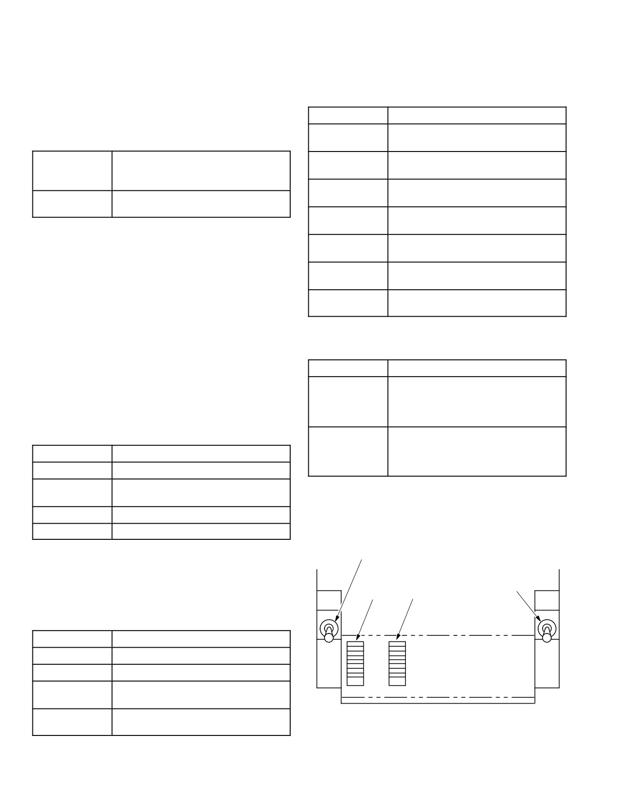
TM 1-1520-251-10
Table 4-14. AND Enhancement Display Status Field
Table 4-17. AND Missile Inventory and Status Field
(cont)
(MISSILE FAULT CONDITION)
MESSAGE
DEFINITION
M
Missile Unlatched on the launcher.
U
PRI=BALT=?
The priority channel code is B with
M
Missile has failed.
missile(s) ready; alternate channel
F
missiles are not ready.
M
Missile launch has aborted/misfired.
AH - 64D
Displayed when no other message is
A
APACHE
displayed.
M
Missile has hangfired.
H
S
Missile launch station has failed.
4.22.7 AND Missile Inventory and Status Field. The
F
AND Missile Inventory and Status fields are located on
both ends of the AND and each field occupies 16 charac-
N
Missile not available.
A
ter spaces, 4 spaces wide and 4 spaces high. Each side is
divided vertically in half to provide space for the status of
O
Missile detected in over-temperature
missiles of 2 launchers on each wing. Each launcher is
T
status.
subdivided into 8 spaces, 2 vertical spaces for each mis-
Table 4-18. AND Missile Inventory and Status Field
sile status message. Messages and their definitions are
(MISSILE STATUS)
contained in tables 4-15 through 4-18.
MESSAGE
DEFINITION
F F
Missile launcher failed.
Table 4-15. AND Missile Inventory and Status Field
A A
I I
(MISSILE TYPE)
L L
S S
Missile launcher ARM/SAFE is in the
A A
SAFE position.
MESSAGE
DEFINITION
F F
L
Laser missile.
E E
A THROUGH
Code of missile in place of L.
4.23 ORT BOTTOM CONTROLS
R
The ORT bottom controls (fig 4-30) consists of those con-
R
RF Missile.
trols necessary to perform certain TADS boresight adjust-
T (STEADY)
Missile seeker in a track state.
ments.
1
Table 4-16. AND Missile Inventory and Status Field
2
3
(MISSILE STATUS)
4
MESSAGE
DEFINITION
S
Missile selected.
R (STEADY)
Missile ready.
R
Priority missile for LOAL engage-
(FLASHING)
ment.
LBA0441
T
Priority missile for LOBL engage-
(FLASHING)
ment.
Figure 4-30. ORT Bottom
Use or disclosure of this information is subject to the restriction(s) on the title page of this document.
4-32
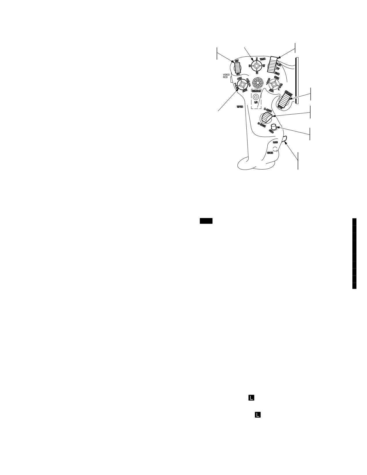
TM 1-1520-251-10
4.23.1 BORESIGHT ENABLE (1). The BORESIGHT
TADS FOV SWITCH
TADS SENSOR
IAT/
SELECT SWITCH
ENABLE switch enables sensor boresighting functions.
OFFSET
SWITCH
Placing the switch to the UP position enables the azimuth
and elevation knobs for various boresight adjustments.
Placing the switch to the CENTER position disables the
azimuth knob, elevation knob, and DVO boresight switch.
Placing the switch to the DOWN position enables the DVO
STORE/
boresight adjust switch.
UPDATE
SWITCH
FCR
4.23.2 DVO Boresight Adjust (2). The DVO BRSIT
SCAN
FCR MODE
switch is used for boresight adjustment to the DVO cross-
SWITCH
SWITCH
hairs. Placing the switch to the UP position causes the
CUED
DVO crosshairs to rotate clockwise. Placing the switch to
SEARCH
the DOWN position causes the DVO crosshairs to rotate
SWITCH
counterclockwise in a helical motion.
LINEAR
MOTION
4.23.3 Azimuth Adjust (3). The azimuth adjust knob is
COMPENSATION
a knurl potentiometer knob used for various boresight ad-
SWITCH
justments.
LBA1038
Figure 4-31. LHG
4.23.4 Elevation Adjust (4). The elevation adjust knob
is a knurl potentiometer knob used for various boresight
4.24.1 Image Auto Track/Offset. The IAT/OFS switch
adjustments.
engages or disengages the image autotracker and offset
tracking.
4.24 LEFT HANDGRIP (LHG)
[
MT
The IAT/OFS switch is used to control the multi - tar-
get tracker (MTT). The IAT position engages the tracker to
The LHG (fig 4-31) in the CPG station provides access to
establish a primary target track. Pressing and holding the
the various sight subsystem control functions.
switch in the IAT position for longer than 0.6 seconds will
initiate manual sizing control of the tracking gates. This
position is also used to adjust an aim point within the pri-
mary tracking gates. The OFS position returns the TADS
LOS to the primary track when offset tracking. This posi-
tion also deletes target tracks when the LOS is on a prima-
ry or secondary track (see 4.26.2).]
4.24.2 TADS Field of View (FOV) Select. The TADS
FOV select switch selects a field of view for the selected
sensor. Placing the switch momentarily to the desired
position will select the respective TADS FOV: Wide (W),
Medium (M), Narrow (N) , or Zoom (Z). The fields of view
available are dependent on the sensor selected.
4.24.3 TADS Sensor Select. The TADS sensor select
switch selects the desired TADS sensor for sighting or ac-
quisition of targets. Placing the switch to the desired posi-
tion will select the respective TADS sensor: FLIR, TV, or
DVO(ORT only).
4.24.4 Store/Update. The STORE/UPDT performs the
update or store function of waypoint/targeting.
4.24.5 FCR Scan
Functions as described on the
collective mission grip (para 4.5.6).
4.24.6 Cued Search
Functions as described on the
collective mission grip (para 4.5.7).
Use or disclosure of this information is subject to the restriction(s) on the title page of this document.
Change 4
4-33
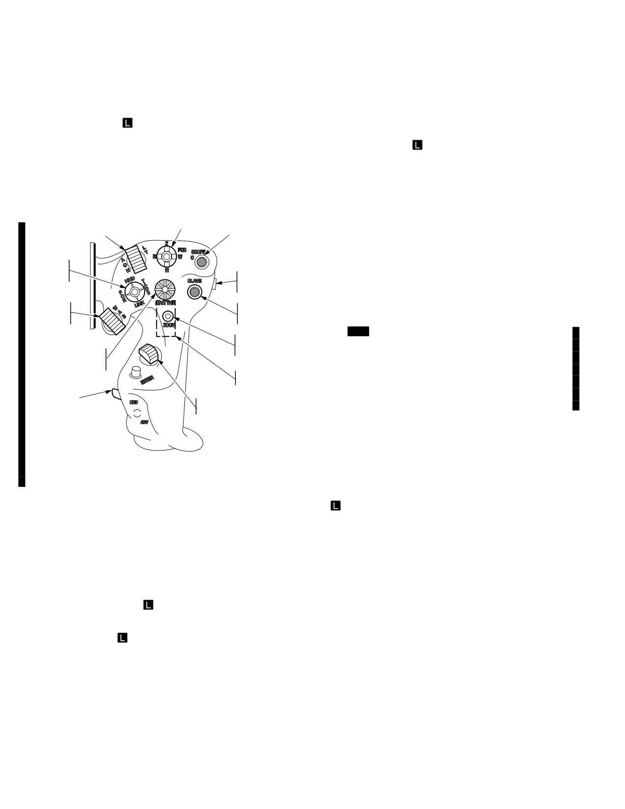
TM 1-1520-251-10
4.24.7
Linear Motion Compensation. The LMC
4.25.6 Sight Slave. The sight SLAVE switch is used to
switch is used to aid in tracking. It compensates for heli-
slave the selected sight and/or provide cueing to the se-
copter movement as well as target movement.
lected acquisition LOS. The SLAVE state remains ON un-
til the SLAVE switch is toggled OFF or an acquisition
4.24.8 FCR Mode
Functions as described on the
selection is made.
collective mission grip (para 4.5.3 ).
4.25.7 Display Zoom
The display ZOOM switch is
4.25 RIGHT HANDGRIP (RHG)
used to view FCR targeting information at approximately a
6:1 zoom display. Pressing the pushbutton causes the se-
The RHG (fig 4-32) in the CPG station provides access to
lected FCR targeting format to be displayed in a zoom for-
the various sight subsystem control functions.
mat centered about the designated next-to-shoot (NTS)
target symbol. Pressing the ZOOM switch again will return
the display to the normal targeting format.
FCR SCAN SIZE SWITCH
LASER TRACKER
CSCOPE
MODE SWITCH
4.25.8 LRFD Trigger. The LRFD trigger is used to ob-
tain laser range and/or to designate a target for laser-
SIGHT
guided munitions. Pressing the trigger to the first detent
SELECT
FLIR
activates the laser transmitter to transmit a series of laser
SWITCH
POLARITY
ranging pulses. Pressing the trigger to the second detent
SWITCH
activates the laser transmitter for ranging and target de-
IAT
SIGHT
signation.
POLARITY
SLAVE
SWITCH
SWITCH
4.25.9 [
MT
Spare Switch. The Spare Switch is used
DISPLAY
ZOOM
to select sequentially through multiple target tracks.
SIGHT
SWITCH
Pressing forward moves the TADS LOS to the next secon-
MANUAL
TRACKER
dary track in sequence and promotes it to primary. Press-
URFD
TRIGGER
ing aft moves the TADS LOS to the previous secondary
track in sequence and promotes it to primary (see
HDD SWITCH
SPARE
4.26.2).]
[MTADS] TRACK PRO−
MOTE
4.25.10 Head Down Display Select. The HDD select
switch is used to select the HDD display for viewing.
LBA1037A
Pressing the HDD pushbutton alternately selects between
the HDD and HOD.
Figure 4-32. RHG
4.25.11
Sensor Manual Tracker. The MAN TRK
thumb force controller is used to control the TADS turret or
FCR
antenna (centerline) to move during manual track-
4.25.1 Sight Select. Functions as described on the col-
ing.
lective mission grip (para 4.5.5).
4.25.12 IAT Polarity. The IAT polarity switch is used to
4.25.2 Laser Tracker Mode. The LT mode switch is
select the FLIR/DTV contrast polarity for the image auto
used to select the mode of the laser spot tracker. Placing
tracker. Placing the switch momentarily to the desired
the switch to the desired position selects the respective
position selects the respective tracker polarity: White (W),
mode: Automatic (A), Off (O), or Manual (M).
Auto (A), or Black (B).
4.25.3 FCR Scan Size
Functions as described on
4.26 TADS TARGET TRACKING
the collective mission grip (para 4.5.4).
Target track mode or cued (predetermined) turret position
commands are generated manually through CPG use of
4.25.4 C - SCOPE
The C - SCOPE switch is used to
the RHG MAN TRK control or electronically by the WP
activate the C - scope display of FCR target information on
and the TEU. Maximum TADS turret gimbal movement is
flight and weapons symbology formats.
+120° and -180° in azimuth, +30° and -60° in elevation.
4.25.5 FLIR Polarity. The FLIR PLRT switch is used to
Target track mode is selected with LHG and RHG
change FLIR polarity.
switches.
Use or disclosure of this information is subject to the restriction(s) on the title page of this document.
4-34
Change 4
TM 1-1520-251-10
4.26.1 Manual Track. Manual tracking is selected by
DTV and FLIR while tracking the target, however, the tar-
pressing the RHG SLAVE switch. To track the target in
get will still be tracked in the original sensor. If the sensor
manual, the CPG operates the RHG MAN TRK control in
is changed while tracking the target, symbology will offset
the direction needed to keep the TADS pointed at the tar-
due to internal paralax correction. The digital image track-
get. If the aircraft or target is moving, the use of LMC will
er functions based on the edge of the target. It also incor-
greatly reduce CPG workload.
porates an inertial track filter which uses previous track in-
formation to determine predicted target locations.
NOTE (ORT)
A primary target track is selected by setting the LHG IAT/
If IAT is selected while DVO is the selected
OFS switch to IAT. The primary autotrack function sur-
sensor and FLIR is on, the DVO FOV will
rounds the target with tracker gates, sizes the gates
default to NFOV and the TEU will use FLIR
based on target edge detection techniques, and initiates
video for tracking the target. DTV video will
automatic tracking. The track number will be displayed
be displayed on the HOD. Since FLIR video
below and to the right of the gates. Pressing and holding
is used to track the target and DVO does not
the switch in the IAT position for longer than 0.6 seconds
display IAT tracker gates, impending break-
will initiate manual sizing control of the tracking gates.
locks cannot be detected and IAT track crite-
Gates will start near the LOS recticle center, then expand
ria cannot be evaluated by the CPG.
and shrink back down, and then begin the growth cycle
again. Sizing will continue until the switch is released at
4.26.2 IAT. IAT automatically tracks targets detected
the desired size. Size will not exceed 50% of the FOV.
with DTV or FLIR. Operation is basically the same using
Once a primary track is established, the TADS LOS may
either sensor. IAT should be used to track, designate, and
be manually slewed to acquire additional tracks or to allow
engage targets when there is sufficient target-to-back-
for offset lasing during Hellfire missile engagements/rang-
ground contrast. IAT is selected by setting the LHG IAT/
ing. The amount of slewing (offset tracking) allowed is lim-
OFS switch to IAT. IAT identifies a target by contrast, sur-
ited to the extent that the primary track cannot be forced
rounds the target with tracker gates, and calculates the
out of the current FOV.
difference between target centerline and selected FOV
center point. Good track criteria (video parameters eva-
Setting the IAT/OFS switch to IAT, when the TADS LOS is
luated by IAT) must be established for proper IAT opera-
within the primary tracking gates, will adjust the ’aim point’
tion. When IAT tracker gates start to flash, an impending
symbol to the desired location on the target/object. Setting
IAT breaklock condition exists. While the impending
the IAT/OFS switch to IAT when the TADS LOS is not
breaklock condition exists, IAT will try to reacquire the tar-
within the primary tracking gates will cause the MTT to at-
get. If IAT does not reacquire the target, within a required
tempt a primary target track as described above.
period of time, IAT enters a stop mode. In the stop mode,
Selecting a second target track will establish that track as
IAT gates change to 4 solid rectangles. When in the stop
the primary track and the previous track will become a
mode, the CPG has manual track control of the TADS
secondary track. A unique flag and flag post symbol will
LOS. If LMC is off when the IAT enters the stop mode,
be displayed in conjunction with the secondary track. The
LOS will stop. If LMC is on, the LOS will continue to move
track number will be displayed within the flag symbol. In
at the last commanded slew rate. Once IAT is selected,
addition, the total number of target tracks will be displayed
setting the IAT/OFS switch to OFS will engage the IAT off-
in the upper right area of the weapon format when the
set tracking capability. In this mode, the MAN TRK thumb-
MTT is in use.
force controller is re-enabled so the TADS may be manu-
ally tracked away from the target to allow for offset lasing
When the TADS LOS is not within the primary tracking
during Hellfire missile engagements/ranging. Actioning
gates, setting the IAT/OFS switch to OFS for less than 0.5
the IAT/OFS switch again to OFS will disengage offset
seconds will disengage offset tracking and slew the TADS
tracking and the TADS will resume automatic tracking of
LOS to the primary track. At this point, the TADS LOS may
the target. Actioning the IAT/OFS switch again to IAT will
again be manually slewed as required. Placing the TADS
disengage automatic tracking and re-enable the MAN
LOS on a primary or secondary track (symbol bolds) and
TRK thumbforce controller for manual tracking.
setting the IAT/OFS switch to OFS will delete that track. If
the primary track is deleted, the previously selected sec-
[
MT
MTT. The TADS multi - target tracker is capable of
ondary track will become the primary track. Pressing and
tracking one primary and two secondary targets using
holding the switch in the OFS position for longer than 0.5
DTV or FLIR. Operation is basically the same using either
seconds anywhere within the FOV will delete all target
sensor, however, tracks can be maintained in only one
tracks. Track delete messages will be displayed in the
sensor at a time. The sensor may be changed between
HAD Weapon Inhibit message field.
Use or disclosure of this information is subject to the restriction(s) on the title page of this document.
Change 4
4-35
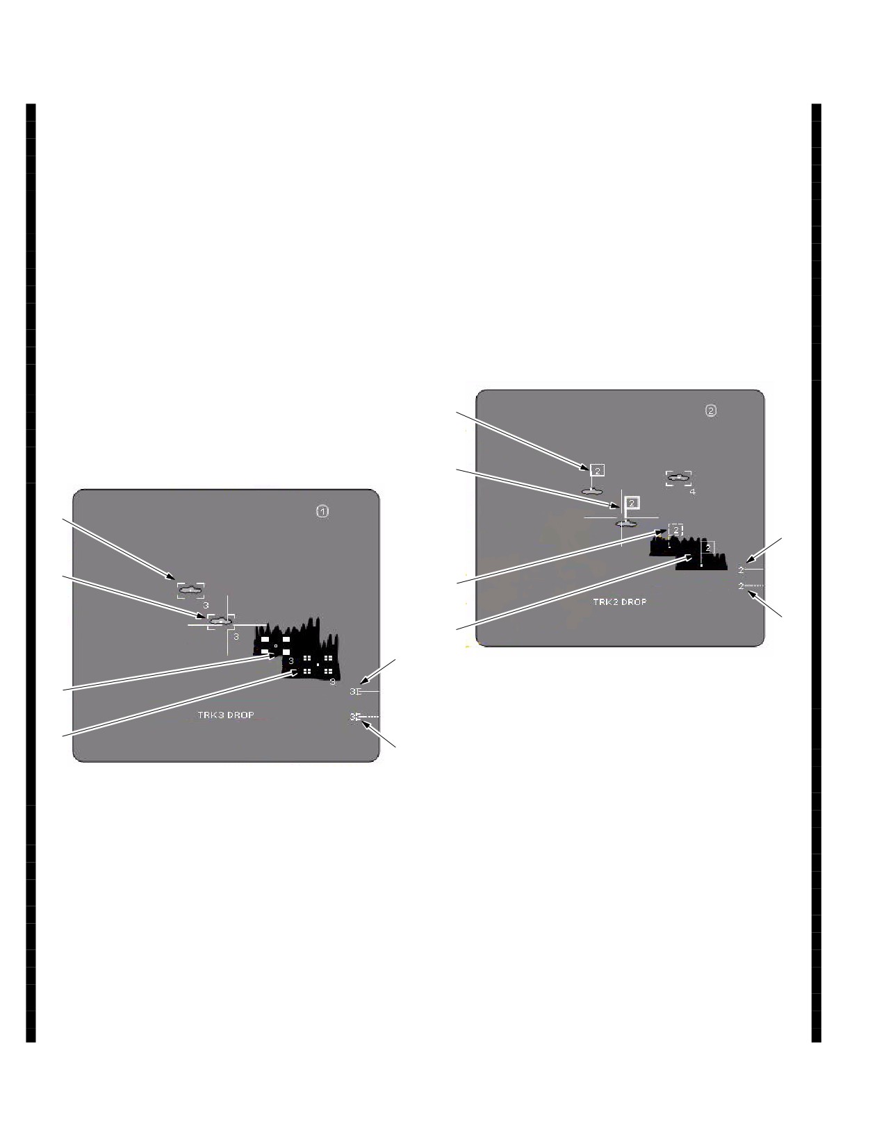
TM 1-1520-251-10
When tracking multiple targets, the RHG SPARE Switch
smaller boxes after 5 seconds of inertial tracking. The
may be used to select sequentially through multiple target
track will be dropped after 10 seconds.
tracks. Pressing forward moves the TADS LOS to the next
5. Inertial Bar An inertial bar symbol with a small
secondary track in sequence and promotes it to the prima-
bracket at the end and associated track number will be
ry track. Pressing aft moves the TADS LOS to the pre-
displayed at the edge of the FOV when an inertial track is
vious secondary track in sequence and promotes it to pri-
out of the FOV.
mary
6. Low Confidence Bar A low confidence dashed
If the selected sight is changed to HMD or FCR when the
bar/bracket and associated track number will be displayed
MTT is in use, tracks will continue to be maintained until
at the edge of the FOV after 10 seconds of inertial tracking
dropped. It is possible to change the selected sight back
out of the FOV. The track will be dropped after 15 sec-
to TADS and resume tracking tasks. If the SLAVE or LINK
onds.
functions are activated, all tracks will be deleted.
b. Secondary Track Symbols. Secondary Track
Primary tracking gates and secondary track symbols are
Symbols (fig 4-32B) are described below.
symbol coded to provide feedback for various track
states.
a. Primary Track Gates. Primary Track Symbols (fig
1
4-32A) are described below. Primary track gates will flash
when approaching 50% of the FOV, limited at FOV edge,
or when the gates are extremely small.
2
1
5
2
3
6
4
5
LBA - 5997
3
Figure 4-32B. Secondary Track Gates
4
6
1. Normal Gate The normal flag symbol is dis-
LBA - 5996
played just above the track aim point.
2. Bold Gate The flag symbol becomes bold
Figure 4-32A. Primary Track Gates
when the TADS LOS is within the symbol’s selectable
area.
1. Normal Gate The normal gates are displayed
3. Inertial Gate The inertial flag symbol is dis-
around the target image; updated based on image proc-
played in dashed lines when the track is being maintained
essing.
inertially because of an obscuration within the FOV.
2. Bold Gate The gates become bold when the
4. Low Confidence Gate The low confidence flag
TADS LOS is within the gates selectable area.
symbol is displayed in small dotted lines after 5 seconds
3. Inertial Gate Inertial gates are displayed as
of inertial tracking. The track will be dropped after 10 sec-
four box symbols when the track is being maintained iner-
onds.
tially because of an obscuration within the FOV.
5 Inertial Bar An inertial bar symbol and associ-
4. Low Confidence Gate Low confidence gates
ated track number will be displayed at the edge of the
are displayed as four box symbols segmented into 4
FOV when an inertial track is out of the FOV.
Use or disclosure of this information is subject to the restriction(s) on the title page of this document.
4-36
Change 4
TM 1-1520-251-10
6. Low Confidence Bar A low confidence dashed
is adjusted internally, then outfront boresight must be per-
bar and associated track number will be displayed at the
formed following the cue update. Cue update procedure is
edge of the FOV after 5 seconds of inertial tracking out of
contained in para 4.55.
the FOV. The track will be dropped after 15 seconds.]
4.30 TADS INTERNAL BORESIGHT
4.26.3 Laser Spot Tracker (LST). The LST provides
The internal boresight aligns the DTV and FLIR sensors to
the CPG with the capability of searching for and tracking
the laser and the DVO (ORT only) to the DTV sensor line of
reflected laser energy of the selected code. The LT mode
sight. Internal boresight shall be performed as part of preflight
switch on the RHG is used to select the desired LST
procedures prior to any firing of laser or weapons when
mode: Automatic (A), Off (O), or Manual (M). Placing the
TADS is used as imaging sensor. Internal boresight can also
LT switch to the A position arms the LST and commands
be performed in flight to ensure boresight accuracy without
the TADS into an automatic 4-bar scan around the TADS
requiring outfront boresight as a follow-up. Internal boresight
LOS at the point of engagement. Placing the LT switch to
procedure is contained in para 4.55.
the M position arms the LST and allows for manual track-
ing of the TADS to search in the area of interest. In either
[
MT
Internal boresight shall be performed as part of pre-
mode, when laser energy of the selected code is detected
flight procedures prior to any firing of laser or weapons when
by the LST, it will auto-track the TADS about the laser en-
TADS is used as imaging sensor. Internal boresight can also
ergy spot. Placing the LT switch to O will turn the LST off
be performed in flight. Internal boresight errors can develop
and release the TADS to normal control. The LST is only
in-flight due to temperature changes within the internal com-
PRF code capable and therefore will not track PIM coded
ponents of TADS (thermal drift). It is recommended that an
laser energy.
internal boresight be accomplished 2 times per 2.5 hour flight.
4.27 TADS DRIFT NULL
TADS internal boresight is an automated process which inde-
The TADS system has the capability to null the turret ser-
pendently boresights the DTV and FLIR sensors. The DTV
vo drift by either auto or manual drift null. Servo drift can
boresight must be performed successfully before the FLIR
be identified as happening whenever the TADS turret is
boresight can be performed. Once the FLIR boresight is
under manual control, the CPG is not making any inputs
complete, the internal boresight is complete. If an ORT is
with the thumbforce controller and the reticle appears to
installed, the DTV boresight must be performed successfully
drift off the aim point. The aim point should remain within
prior to boresighting the DVO.
the narrow FOV of the DTV for 30 seconds. If it does not,
or a lesser amount of drift is desirable, perform Manual
Initiating an internal boresight automatically sets the CPG se-
Servo Drift Null (para 4.55.5 or 4.55.5A). Auto Drift Null is
lected sight to TADS, the sensor to TV and the FOV to nar-
active from the time the TADS is first turned on. It is only
row. A standby prompt is displayed while the TADS turret
inactive when the manual servo drift procedure is being
slews to the boresight position and prepares for the process.
performed. Auto Drift Null is not as precise as Manual Ser-
At initial powerup, the system will conduct an automatic cue
vo Drift Null so some residual servo drift will always be
search which will take less than 90 seconds before indicating
present when it is active.
it is ready for boresight. Subsequent attempts to perform an
internal boresight under the same powerup will include a
Paragraphs 4.27.1 and 4.27.2 deleted
preparation time of less than 15 seconds as it will not involve
a cue search. During these waits, boresight target images will
4.28 TADS BORESIGHT OPERATION
appear and disappear in TADS video. These images do not
necessarily align with weapon symbology and are not manip-
Boresight aligns TADS sensors to a coincident LOS. Bore-
ulated in any way by the CPG.
sight includes an internal and outfront boresight. TADS
When the system is ready, a laser warning window and bore-
boresight is initiated by selecting the weapon page
sight procedure prompt will be displayed. The CPG will be re-
BORESIGHT button and selecting the internal or outfront
quired to arm the laser and pull the laser trigger during DTV
boresight button. Boresight procedures are contained in
internal boresight, otherwise, no action is required by the
paragraph 4.55.
CPG during FLIR internal boresight. If the TADS FLIR is not
4.29 TADS CUE UPDATE
cooled upon completion of DTV boresight, a not cool status
will be displayed and the process will be ended. In addition,
Performance of cue update ensures that the TADS turret
status windows will be displayed to indicate when the bore-
is in proper position relative to the boresight assembly
sight(s) are in progress, complete, or failed. Internal boresight
prior to firing the laser for internal boresight. If cue update
procedure is contained in para 4.55.]
Use or disclosure of this information is subject to the restriction(s) on the title page of this document.
Change 4
4-36.1
TM 1-1520-251-10
4.31 TADS OUTFRONT BORESIGHT
4.32 TADS MANUAL BORESIGHT
The purpose of the TADS manual boresight is solely to re-
WARNING
capture or center the laser spot. This boresight procedure
should not be considered acceptable for normal flight op-
erations. The manual boresight procedure is contained in
The narrow and zoom FOV TADS FLIR
para 4.55.
imagery has inaccuracies for lasing or
weapons direction following TADS inter-
4.33 TADS ANTI-ICE
nal boresight. TADS outfront boresight
When the pilot or CPG selects anti-ice using the aircraft
validation and adjustment (if necessary)
UTIL page ANTI-ICE SENSOR button and the helicopter
shall be performed prior to using the
is off the ground, 115 Vac is applied to the TADS shroud
TADS FLIR imagery for laser or weapons
window and a shroud frame heater. TADS anti-ice can be
operations.
selected when the aircraft is on the ground by using the
GND button.
Performance of outfront boresight ensures FLIR LOS is in
4.34 FCR DESCRIPTION
coincidence with laser LOS. Outfront boresight should be
NOTE
checked prior to any firing of laser or weapons when
TADS FLIR is used as the imaging sensor. Outfront bore-
The FCR will provide reliable data while ma-
neuvering up to 20° in roll and +20° to - 15°
sight must be performed after a cue update adjustment.
in pitch. Flight outside these parameters
Target requirements for the outfront boresight procedure
may result in degraded FCR performance.
are as follows:
The FCR is an integrated radar system with a mast-
1.
A target a minimum of 0.5 km away from the he-
mounted transmitter and receiver. The FCR detects, lo-
licopter is required. Target must be clearly vis-
cates, and classifies ground and airborne targets and pro-
ible and trackable through both FLIR and TV
vides terrain profile signatures when operating in limited
sensor NFOV. Target must have the same cen-
adverse weather or obscured visibility conditions. The
ter as viewed in both FLIR and TV sensors.
FCR augments the helicopter’s weapon delivery capabili-
ty through the use of a target acquisition fire control radar,
2.
Outfront boresight procedure is contained in
coupled with a Radar Frequency (RF) guided seeker ver-
para 4.55.
sion of the Hellfire missile. A Radar Frequency Interferom-
eter (RFI) is incorporated to provide threat emitter warn-
ing, direction finding, and cueing. These coordinates are
sorted and sent to the display processor for target symbol-
ogy presentation on the FCR page or TSD page. Non-vol-
atile memory is zeroed-out using the MASTER ZEROIZE
Switch described in chapter 2.
4.34.1 Mast Mounted Assembly (MMA). The MMA
(fig 4-33) is mounted to the aircraft on a pedestal tube
which contains a derotation assembly. Electrical power
and signal/RF transmissions pass through the mast by
way of a slipring/rotary joint assembly. The slipring as-
sembly transfers prime power and signal information be-
tween the two portions of the assembly as they are rotated
with respect to each other. The slipring housing also con-
tains the accelerometer sensor assembly for the pedestal.
A rotary joint coupler provides a path for four RF channels.
The MMA to aircraft interface is a blindmate connector.
The MMA dome and baseplate are made of a honeycomb
core sandwiched between carbon graphite fiber/epoxy
prepreg composite. The composites reduce weight and
provide structural integrity. The MMA stands 32 in. high
and weighs 257 lb. The MMA is cooled by air drawn from
the surrounding environment.
Use or disclosure of this information is subject to the restriction(s) on the title page of this document.
4-36.2
Change 4
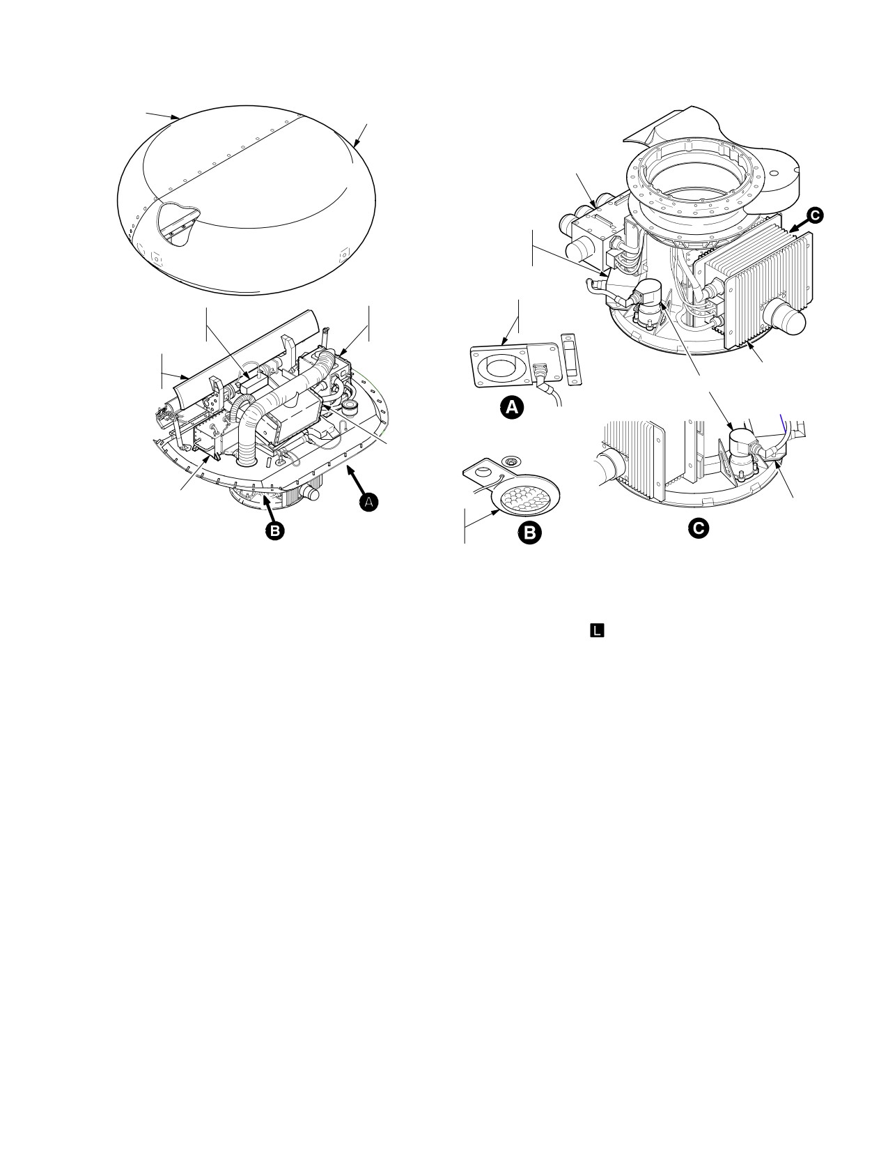
TM 1-1520-251-10
RADOME
AFT DOME
RFI ANTENNA
AZIMUTH
ELECTRONICS
UNIT
MAIN
QUARTZ
POWER
COOLING
RAT
SUPPLY
FA
SENSOR
CONTROLLER
N
ELEVA−
GIMTB
AL
RFI RECEIVER
AS−
AZIMUTH ACTUATOR
SEMBLY
TRANSMITTER
RECEIVER
AZIMUTH
INERTIAL
ELECTRONICS
PARTICLE
UNIT
SEPARATOR
LBA2582
Figure 4-33. MMA Major Components
4.34.2 MMA Components. The MMA is made up of the
4.35 FCR PAGE
following major components:
The FCR page is used to present the display of radar in-
• Power Supply Controller
formation and to functionally control much of the FCR and
RFI moding. It provides the controls, graphics, and sym-
• Transmitter
bols required to operate the selected FCR mode.
• Receiver
4.35.1 FCR Page Selection. The FCR page can be ac-
cessed in one of three ways in either crew station: 1) se-
• Main Cooling Fan
lecting the FCR subsystem bezel button, 2) selecting the
• Inertial Particle Separator
FCR page button from the MENU page, or 3) selecting the
sight select switch to FCR.
• Elevation Gimbal Assembly (EGA)
4.35.2 FCR Page Formats. The FCR page provides in-
• Quartz Rate Sensor (QRS)
formation to the aircrew based on the selected mode of
the radar: Ground Targeting Mode (GTM), Radar Map
• Radome
(RMAP), Air Targeting Mode (ATM), or Terrain Profiles
Mode (TPM). The format of the FCR page is displayed in
• Aft Dome
the Plan Position Indicator (PPI) or B Scope format ac-
cording to the selected FCR mode:
• Azimuth Actuators
• Ground Targeting Mode (PPI format)
• Azimuth Electronics Unit
• Radar Map (B Scope format)
• RFI Antenna
• Air Targeting Mode (PPI format)
• RFI Receiver
• Terrain Profiles Mode (PPI format)
Use or disclosure of this information is subject to the restriction(s) on the title page of this document.
4-37
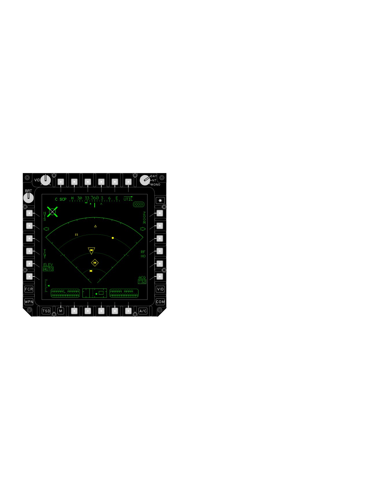
TM 1-1520-251-10
4.35.3 FCR Page Formats on ORT HDD/HOD. The
a. GTM Scan Sector Symbol. The scan sector
FCR page is available on the ORT HOD/HDD by the use
symbol is displayed in the mode selected by the crew-
of the VID SEL switch and the HDD switch. Selections
member (Wide, Medium, Narrow or Zoom). Current mode
from the FCR formats ORT HOD/HDD are accomplished
is displayed in full intensity with other modes displayed in
solely by use of the display cursor ENTER function. Mod-
partial intensity, if applicable. FCR Page - GTM Format
ing of these selections are the same as for FCR page op-
scan sectors function as follows:
erations described in the paragraphs to follow. Control
and placement of the display cursor is described in chap-
b. FCR Footprint. The GTM targeting scan sectors
ter 2.
are displayed in full intensity and are based on the se-
lected scan size: Wide, Medium, Narrow, and Zoom.
4.35.4 FCR Page - GTM Format. The GTM format
(fig 4-34) is displayed in the PPI format made up of a scan
1.
The wide scan sector symbol represents a 90°
sector outline with partial intensity range arc lines and azi-
scan sector (45° either side of centerline). The
muth tic marks which correspond to each scan size. The
wide scan sector displays in partial intensity
scan sector is overlaid onto radar map video. The FCR
when any other scan size is selected.
page buttons function identically in either GTM or RMAP
format.
2.
The medium scan sector symbol represents a
45° scan sector (22.5° either side of centerline).
The wide scan sector displays in partial intensi-
ty.
3.
The narrow scan sector symbol represents a 30°
scan sector (15° either side of centerline). The
wide and medium scan sectors displays in par-
tial intensity.
4.
The zoom scan sector symbol represents a 15°
scan sector (7.5° either side of centerline).The
wide, medium and narrow scan sectors displays
in partial intensity.
5.
RFI tic marks. A single RFI tic mark is displayed
along the outer left and right boundary line of the
GTM and RMAP wide sector scan symbols. The
tic marks represent a reference point 90° left
and right of scan centerline relative to the dis-
play of RFI threat symbols along the perimeter
of the sector scan (helicopter).
LBA2587A
6.
Arcs and tics. Each arc represents a 2 km dis-
tance in even increments (2, 4, 6 and 8) and
each tic mark represents a 2 km distance in odd
Figure
4-34.
FCR Page - GTM Format
increments (1, 3, 5, and 7).
Use or disclosure of this information is subject to the restriction(s) on the title page of this document.
4-38
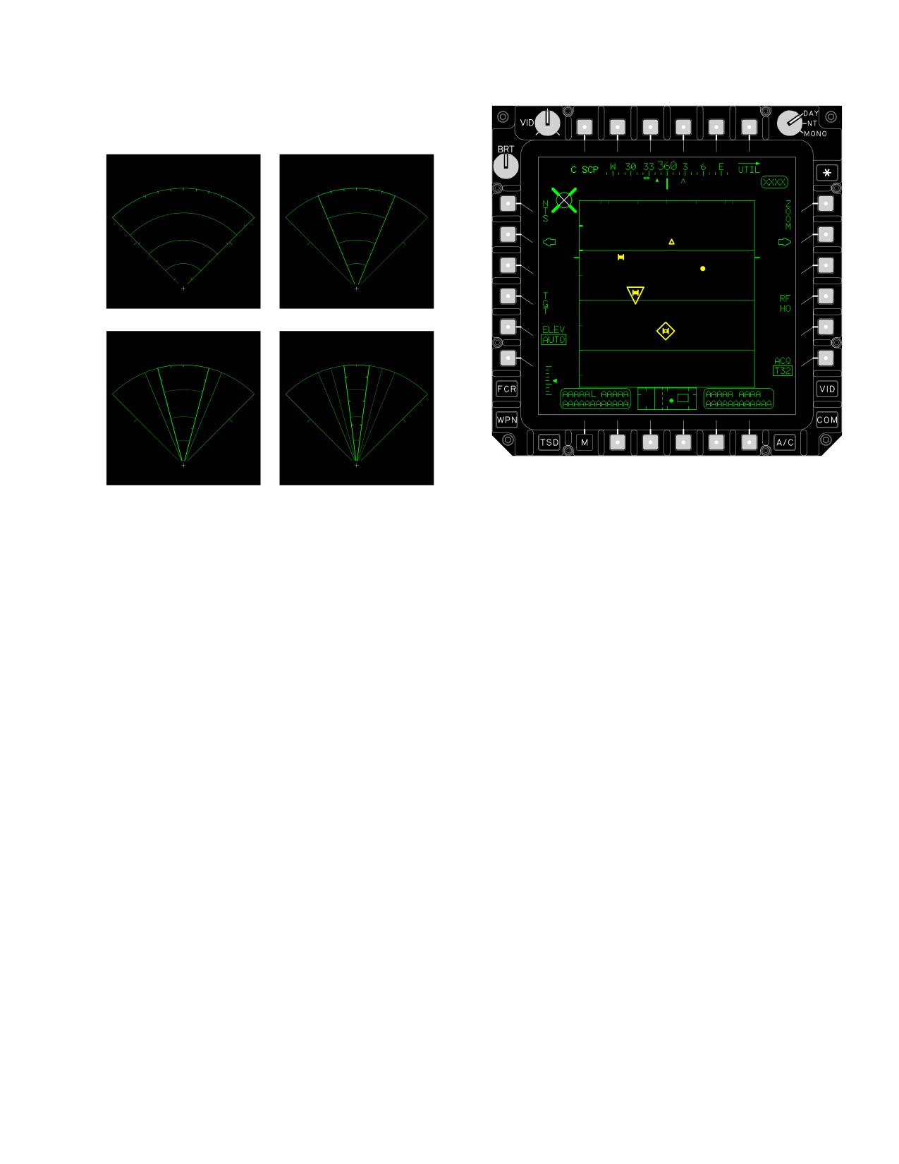
TM 1-1520-251-10
A view of all scan sector modes is shown in figure 4-35.
WIDE SCAN
MEDIUM SCAN
NARROW SCAN
ZOOM
LBA0486A
LBA2591A
Figure 4-36. FCR Page - RMAP Format
a. RMAP Scan Sector Symbol. The scan sector
Figure 4-35. GTM Scan Sectors
symbol is displayed in the mode selected by the crew-
member (Wide, Medium, Narrow or Zoom). Current mode
4.35.5 FCR Page - RMAP Format. The RMAP format
is displayed in full intensity with other modes displayed in
(fig
4-36) provides radar information within a B-scope
partial intensity, if applicable. FCR Page - RMAP Format
(rectilinear format) scan sector outline with partial intensi-
scan sectors function as follows:
ty range lines and azimuth tic marks which correspond to
b. FCR Footprint. The GTM targeting scan sectors
each scan size. The scan sector is overlaid onto radar
are displayed in full intensity and are based on the se-
map video. The FCR page buttons function identically in
lected scan size: Wide, Medium, Narrow, and Zoom.
either GTM or RMAP format.
1. The wide scan sector symbol represents a 90°
scan sector (45° either side of centerline). The
wide scan sector displays in partial intensity
when any other scan size is selected.
2. The medium scan sector symbol represents a
45° scan sector (22.5° either side of center-
line).The wide scan sector displays in partial in-
tensity.
3. The narrow scan sector symbol represents a 30°
scan sector (15° either side of centerline). The
wide and medium scan sectors displays in par-
tial intensity.
4. The zoom scan sector symbol represents a 15°
scan sector (7.5° either side of centerline). The
wide, medium and narrow scan sectors displays
in partial intensity.
Use or disclosure of this information is subject to the restriction(s) on the title page of this document.
4-39

TM 1-1520-251-10
5. RFI tic marks. A single RFI tic mark is displayed
• R4
RFHO button
along the outer left and right boundary line of the
• R6
ACQ button
GTM and RMAP wide sector scan symbols. The
a. C-SCP Button. The C-SCP button is used to call
tic marks represent a reference point 90° left
and right of scan centerline relative to the dis-
up the C-scope target symbols for display on the flight and
play of RFI threat symbols along the perimeter
weapons symbology format. Selecting the C-SCP button
of the sector scan (helicopter).
will cause the display of virtual FCR target symbols on the
HMD in the pilot station, on the HMD and ORT HOD/HDD
in the CPG station, and on the MPDs when the appropri-
6. Lines and tics. Each line represents 2 km dis-
ate video is selected.
tance in even increments (2, 4, 6 and 8) and
each tic mark represents a 2 km distance in odd
b. FCR UTIL Page Button. The FCR UTIL page
increments (1, 3, 5, and 7).
button is used to access FCR system utility functions.
A view of all scan sector modes is shown in figure 4-37.
c. NTS Button. The NTS button is used to select
the next valid target in the priority target list as the NTS
WIDE SCAN
MEDIUM SCAN
target. Selecting an FCR target symbol with the display
cursor will designate that target as the FCR NTS. The
MPD display cursor will automatically be placed in the ac-
tive area of this button at the completion of the first scan of
a scan burst. This allows rapid NTS target selection using
the cursor ENTER function. The cursor operation on the
FCR page is described in chapter 2. This button is only
displayed when valid target data is present.
NOTE
If the Pilot’s selected sight is FCR, the cent-
NARROW SCAN
ZOOM
erline is commanded to the selected acquisi-
tion source. If a left/right arrow button is se-
lected, the centerline is offset as described
below. To force the centerline back to the ac-
quisition LOS, the Pilot must reselect the
FCR sight select switch on the collective.
d. Left/Right Arrow Buttons. The left/right arrow
buttons are only displayed if the FCR is the selected sight.
LBA2590A
They are used to rapidly position the FCR centerline to the
left or right of the helicopter centerline. Selecting the left or
Figure 4-37.
RMAP Scan Sectors
right centerline buttons will cause the FCR centerline to be
adjusted to the left or right based on the selected scan
size. The centerline will be adjusted to the right or left so
4.35.6
FCR Page - GTM/RMAP Format pages. Each
as to effect total scan width coverage of the area adjacent
of the GTM/RMAP pages contains the following unique
to the previously selected area. The FCR centerline will
buttons:
remain heading stabilized at each position until comman-
ded to a new position. If the FCR is slaved, the left/right
• T1
C-SCP button
arrow buttons are barriered in the CPG crewstation. In
• T6
FCR UTIL button
addition, the MAN state allows the antenna azimuth posi-
• L1
NTS button
tion to be manually adjusted using the MAN TRK thumb
force controller.
• L2
Left Arrow button
• L4
TGT button
e. TGT Button. The TGT button is used for the
selection of FCR target data (fig 4-38) to be stored into the
• L5
ELEV button
permanent Target/Threat file. Selecting the TGT button
• R1
ZOOM button
sets the display cursor for selecting/storing any FCR tar-
• R2
Right Arrow button
get symbol and calls up the store status window in the
Use or disclosure of this information is subject to the restriction(s) on the title page of this document.
4-40
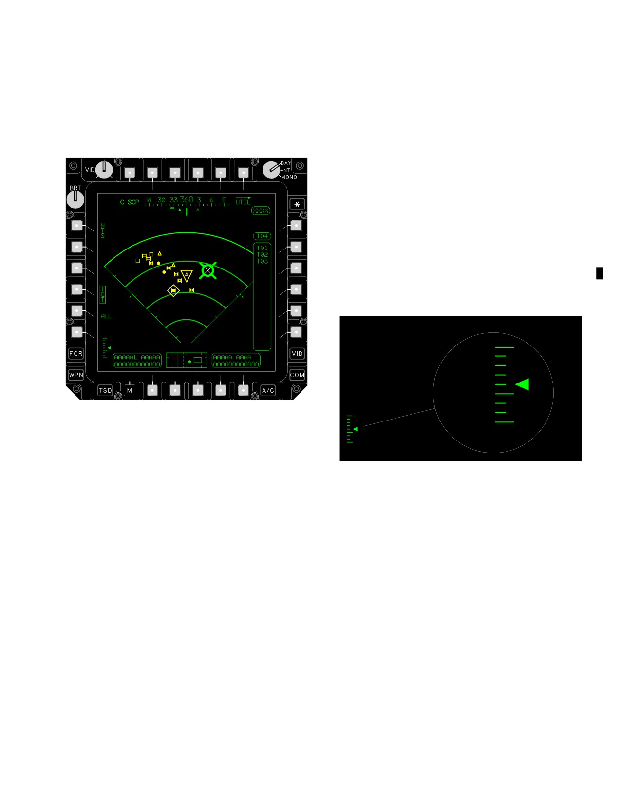
TM 1-1520-251-10
right area of the FCR page. In addition, it calls up the ALL
f. ELEV Button. Antenna elevation control is se-
button. Selecting an FCR target symbol with the display
lected using the ELEV button (fig 4-39) on the FCR page
cursor will store that target data to the target/threat file.
GTM format. Two options are available to the crewmem-
Again selecting the TGT button will exit the target select
ber: AUTO or manual. Depressing the ELEV button while
function and return the format to normal operation. This
in the AUTO mode will remove the AUTO placard and
button is only displayed when valid target data is present.
present up and down arrows on the display for manual
control. Selecting the up arrow button will cause the an-
tenna position to elevate up one setting or to the next
higher setting when starting between settings. Selecting
the down arrow button will cause the antenna to move
down one setting or to the next lower setting when starting
between settings. When the antenna is at the uppermost
setting, the up arrow symbol will not be available. Con-
versely, when the antenna is at the lowest setting, the
down arrow symbol will not be available. If TADS power is
applied, selecting manual will allow the CPG to slew an-
tenna elevation using the RHG MAN TRK control. The de-
grees shown in figure 4-39 are lower bar elevations. The
upper bar elevation will vary with altitude.
25
º
18.75
º
12.5
º
6.25
º
0
º
(Default)
6.25
º
LBA2011A
12.5
º
18.75
º
25
º
Figure 4-38. TGT Store Selection
ELEVATION SCALE
(1) ALL Button. The ALL button is used to rap-
LBA2596
idly store all of the displayed FCR target data. Selecting
the ALL button stores all of the top priority FCR target
Figure 4-39. GTM Elevation Setting
data to the target/threat file and calls up a larger status
window.
g. Display ZOOM Button. Selection of the ZOOM
(2) Store Status Window. The store status win-
button activates the zoom function. When the display cur-
dow provides the file address of the next target to be se-
sor is positioned within the FCR target area, the display
lected/stored (boxed) and the list of file addresses of tar-
cursor symbol is changed to a ZOOM cursor (para
gets stored during the current iteration of TGT selection.
2.21.4). Placement of the ZOOM cursor represents the
This data is displayed for reference by the crew member
area to be zoomed allowing better viewing of target arrays
for future use.
where the targets are in close proximity to each other.
Use or disclosure of this information is subject to the restriction(s) on the title page of this document.
Change 3
4-41
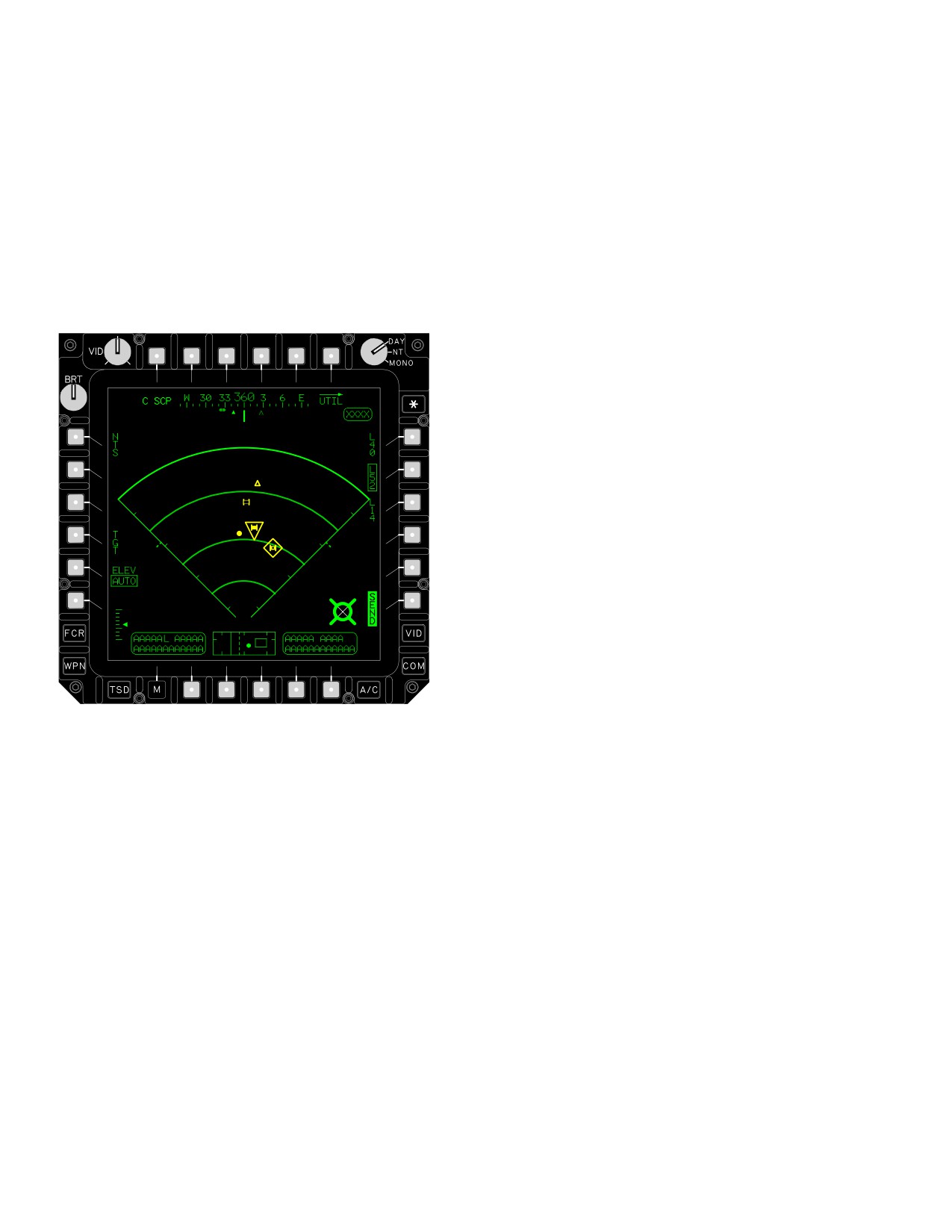
TM 1-1520-251-10
h. RFHO Button. The RFHO button is used for rap-
(2) SEND Button. The SEND button is used to
id transmission of the FCR next-to-shoot (NTS) (fig 4-40)
activate the IDM and transmit the RF handover target data
target information via the IDM to another LBA system for
to the selected subscriber.
engagement. Selecting the RFHO button will select the
FCR NTS target data for transmission and call up the Sub-
(3) ACQ Button. The ACQ button is described
scriber Identifier buttons based on the selected IDM net-
in Section I of this chapter.
work on the right side of the FCR page. Selecting a Sub-
scriber Identifier button will call up the IDM SEND button
4.35.7 GTM Antenna Elevation Control when MMA is
on the right side of the FCR page. This button is only dis-
Masked. In automatic elevation control (fig 4-41), anten-
played when valid target data is present.
na elevation is set to cover FCR minimum and maximum
range based on radar altimeter altitude. In situations
where the FCR is scanning behind a hill or mountaintop,
the radar altitude may be such that the automatic setting
will not cover the desired area of interest. A suggested
method of overcoming this situation requires manual ad-
justment of antenna elevation and multiple scans to
bracket the area of interest.
4.35.8 GTM Manual Elevation Control Operations.
a. Select RMAP with radar video.
b. Set antenna elevation manually to an angle esti-
mated to cover the area of interest or the lowest setting.
c. Conduct a single scanburst and observe RMAP
display.
d. Conduct the following steps until RMAP video
shows ground returns at minimum range with one eleva-
tion setting lower than a blank area presentation.
LBA2010A
(1) If the display presents ground returns at mini-
mum range, set the elevation angle up one setting and
conduct a single scanburst.
Figure
4-40.
RFHO Selection
(2) If the minimum range area still displays ground
returns, set the elevation angle up one setting and con-
• T5 - T6, R1 - R5 Subscriber buttons
duct a single scanburst.
• R6
SEND button
(3) If the minimum range area is blank, set the
(1) Subscriber Identifier Button.
The Sub-
elevation angle down one setting and conduct a single
scriber Identifier buttons are used to select the desired
scanburst. A blank area indicates the main beam is set to
subscriber to which the RF handover target data will be
an angle which does not provide coverage at the minimum
transmitted.
range.
Use or disclosure of this information is subject to the restriction(s) on the title page of this document.
4-42
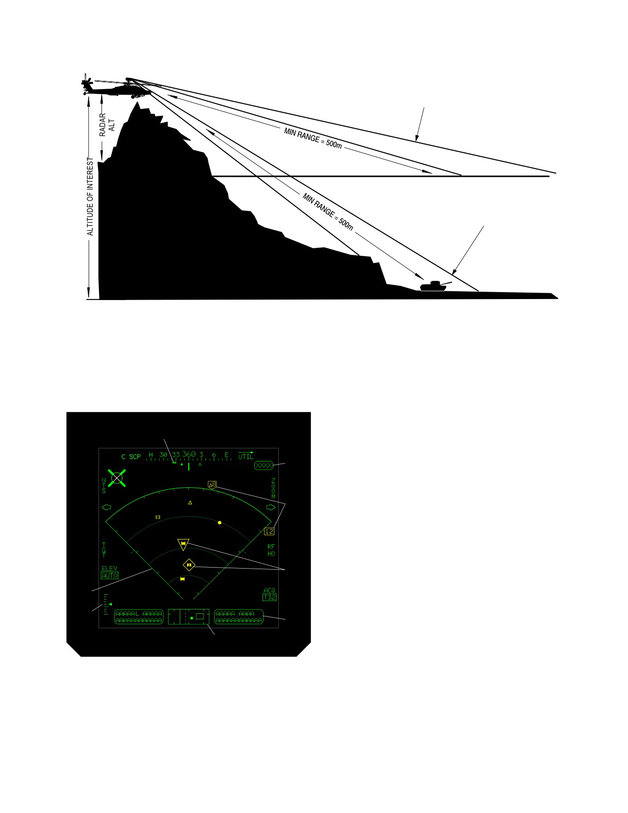
TM 1-1520-251-10
POSITION OF MAIN BEAM WITH AUTO SETTING AT LOW RADAR ALTITUDE
OR
APPARENT GROUND PLANE BASED ON RADAR ALTITUDE
POSITION OF MAIN BEAM WITH AUTO SETTING
AT HIGH RADAR ALTITUDE
OR
MANUAL SETTING REQUIRED TO DETECT TARGET
AT STEEP LOOKDOWN ANGLE
GROUND PLANE
OF INTEREST
LBA2599
Figure 4-41. Manual Elevation Control Considerations
4.35.9 GTM/RMAP SYMBOLOGY. The following sym-
1. Scan Sector Symbol. The scan sector symbol is
bols (fig 4-42) are displayed on the GTM and RMAP for-
displayed in the mode selected by the crewmember
mats.
(Wide, Medium, Narrow or Zoom). Current mode is dis-
played in full intensity with other modes displayed in par-
tial intensity, if applicable.
2. Elevation Scale. The moving antenna elevation
3
pointer is displayed along the right side of the antenna
elevation scale located in the lower left area of the format.
4
The pointer moves up and down along the scale to indi-
cate the elevation setting of the FCR antenna. The long tic
mark within the scale provides indications with reference
5
to the zero setting.
3. Heading Scale and Symbols. The heading
scale and associated symbols are as described in chapter
2.
6
4. Total Target Count Status Window. The total
1
target count status window appears when targets are se-
lected. It provides a total number of targets selected by
2
the radar within a scanburst. The status window digital
7
readout is from 1 to 1023 in GTM/RMAP.
8
5. RFI Threat Symbols. RFI threat symbols repre-
LBA2587A
senting RFI detected emitters are displayed on the periph-
ery of the radar scan sector to indicate the direction to the
threat. Up to 10 RFI threat symbols can be displayed at a
Figure
4-42. GTM/RMAP Symbology
time.
Use or disclosure of this information is subject to the restriction(s) on the title page of this document.
4-43
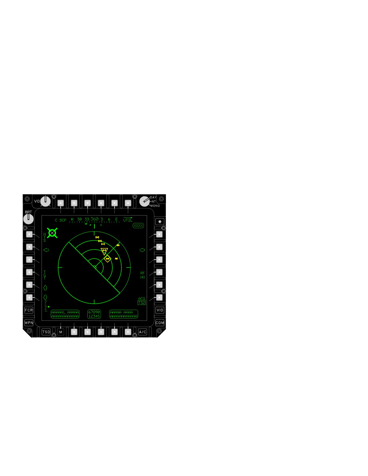
TM 1-1520-251-10
6. FCR Priority Target Symbols. FCR target prior-
4.35.11 ATM Target Processing/Prioritization. ATM
ity symbols represent the highest priority targets detected
target symbols are displayed in any given scan. Target
and classified for a scanburst. Up to 16 FCR target sym-
data is displayed and updated as it is detected during the
bols can be displayed for any given scanburst (Refer to
scan to derive priority target characteristics (velocity and
4.44.5 for target symbol descriptions).
classification). The symbols represent the highest priority
target detected and classified for that scan. The target
7. High Action Display. The High Action Display is
classification process is:
as described in paragraph 4.16.
• Priority target data, total target count, and total
targets are purged at the start of each single scan
8. FOR Symbols. The Field of Regard and
and updated during the scan.
associated symbols are described in paragraph 4.14.
• Symbols are displayed during the scan.
4.35.10 FCR Page ATM Format.. The ATM format (fig
• NTS is displayed at the end of the first scan and is
4-43) provides radar information within a plan PPI circular
updated by the WP as target information is
sector scan outline with partial intensity range arc lines
prioritized by the FCR.
and azimuth tic marks at 90° increments. The ATM pro-
vides the same functional controls as the GTM and RMAP
• RFI target merges are displayed during any scan.
formats except that is does not include the ZOOM button
or automatic control of the antenna elevation. In addition,
a. ATM Scan Sector Symbol. The ATM scan sec-
there is no FOR symbology displayed in the ATM format.
tor is displayed in full intensity and is based on the se-
lected scan size: Wide, Medium, Narrow, and Zoom. Cur-
rent mode is displayed in full intensity with other modes
displayed in partial intensity, if applicable. FCR Page -
ATM Format scan sectors function as follows:
• The wide scan sector symbol represents a 360°
scan sector. The wide scan sector remains
displayed in partial intensity when any other scan
size is selected.
• The medium scan sector symbol represents a
180° scan sector (90° either side of centerline).
• The narrow scan sector symbol represents a 90°
scan sector (45° either side of centerline). The
wide and medium scan sectors remains displayed
in partial intensity.
• The zoom scan sector symbol represents a 45°
degree scan sector (22.5° either side of center-
line). The wide, medium, and narrow scan sectors
remains displayed in partial intensity.
LBA0487A
• The ATM blanking symbol will appear whenever
the FCR is looking towards the tail section of the
Figure
4-43.
FCR Page - ATM Format
aircraft.
Use or disclosure of this information is subject to the restriction(s) on the title page of this document.
4-44
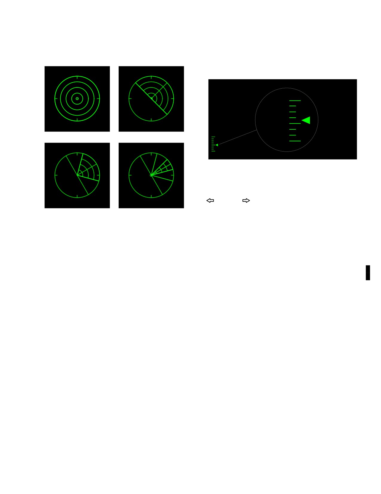
TM 1-1520-251-10
A view of all scan sector modes is shown in figure 4-44.
WIDE SCAN
MEDIUM SCAN
23 º
18 º
13 º
8 º
(DEFAULT) 3 º
2
º
7
º
NARROW SCAN
ZOOM
12
º
ELEVATION SCALE
LBA2597
Figure 4-45. ATM Elevation Setting
4.35.13 ATM Azimuth Scan Centerline Control. Left
(
) or right (
) FCR page buttons are used to rapidly
position the FCR azimuth scan centerline to the left or
LBA2592A
right of the current FCR azimuth scan centerline. The FCR
azimuth scan centerline will be set to the left or right to
Figure 4-44. ATM Scan Sectors
give total scan width coverage of the area adjacent to the
previously selected area. The new centerline selection will
4.35.12 ATM Elevation Control. The up/down arrow
be displayed as shown in figure 4-46. The FCR azimuth
buttons are displayed continuously in the ATM. They are
scan centerline will remain heading stabilized until com-
used to manually adjust the antenna elevation up or down
manded to a new azimuth position. If TADS power is ap-
incrementally during air targeting. Selecting the up arrow
plied, the CPG can slew antenna azimuth using the RHG
button will cause the antenna position to elevate up one
MAN TRK control. If the FCR is slaved to an acquisition
setting or to the next higher setting when starting between
source in the CPG station, manual controls (arrow buttons
settings. Selecting the down arrow button will cause the
and MAN TRK controller) will be inhibited. Pilot station left
antenna to move down one setting or to the next lower
or right arrow button selection, after the FCR is sight se-
setting when starting between settings. When the antenna
lected, will deselect FCR slave to the acquisition source.
is at the uppermost setting, the up arrow symbol will not
For the pilot to slave the FCR to the acquisition source
be available. Conversely, when the antenna is at the low-
again, the FCR must be deselected as sight and selected
est setting, the down arrow symbol will not be available.
again.
Use or disclosure of this information is subject to the restriction(s) on the title page of this document.
Change 3
4-45
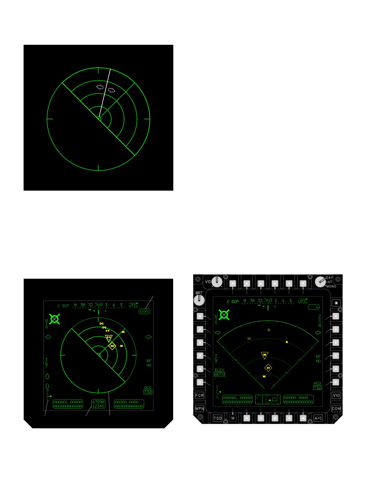
TM 1-1520-251-10
1. Scan Sector Symbol. The ATM scan sector
WIPER MOVEMENT
symbology is displayed in full intensity and is based on the
LEFT AND RIGHT
selected scan size: Wide, Medium, Narrow, and Zoom.
Current mode is displayed in full intensity with other
modes displayed in partial intensity, if applicable.
2. Elevation Altitude Status Window. The eleva-
tion altitude status window is displayed in the lower center
area of the format. The upper and lower altitude digital
readouts represent the upper and lower altitude of FCR
coverage at maximum range and is referenced from the
aircraft and antenna elevation setting. Each altitude value
for digital readout is from - 32,767 feet to +32,768 feet, in
one foot increments.
3. Elevation Scale. The moving antenna elevation
pointer is displayed along the right side of the antenna
elevation scale located in the lower left area of the format.
The pointer moves up and down along the scale to indi-
cate the elevation setting of the FCR antenna. The long tic
LBA2598
mark within the scale provides indications with reference
to the zero setting.
Figure 4-46. ATM Azimuth Scan Centerline Control
4. Total Target Count Status Window. The total
4.35.14 ATM Symbology. The ATM scan sector
target count status window (fig 4-48) appears when tar-
symbology (fig 4-47) is displayed in full intensity and is
gets are detected. It provides a total number of targets de-
based on the selected scan size: Wide, Medium, Narrow,
tected by the radar within a scanburst. The status window
and Zoom. Current mode is displayed in full intensity with
digital readout is from 1 to 1023 in ATM.
other modes displayed in partial intensity, if applicable.
4
3
2
1
LBA2589A
LBA0487A
Figure 4-47. ATM Symbology
Figure 4-48. Total Target Count Status Window
Use or disclosure of this information is subject to the restriction(s) on the title page of this document.
4-46
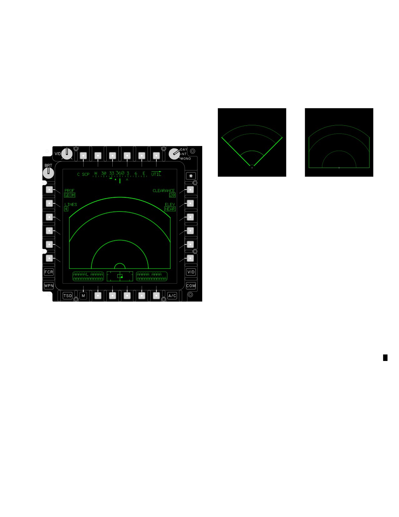
TM 1-1520-251-10
4.35.15 FCR Page - TPM Format. The TPM format (fig
• Arcs. Each arc represents the following: first arc =
4-49) provides radar information within a PPI sector scan
100m, second arc = 1000m, third arc = 2000m and
outline with partial intensity range arc lines. Two scan sec-
fourth arc = 2500m.
tor sizes are automatically displayed based on ground
speed. The FCR centerline is set to the aircraft centerline
A view of all scan sector modes is shown in figure 4-50.
in this mode. The scan sector is overlaid onto radar map
video converted to shades of gray. Line distances are 100
m, 1000 m, 2000 m, and 2500 m. Obstacle symbols and
NARROW SCAN
WIDE SCAN
radar video are displayed in geometric fidelity within a
sector scan. The TPM format provides the following selec-
tions, status windows, and graphics:
LBA2594A
Figure 4-50. TPM Scan Sectors
The FCR page - TPM format contains the following
unique buttons:
• T1
C-SCP button
• T6
UTIL button
• L1
PROF button
• L2
LINES button
• R1
CLEARANCE button
• R2
ELEV button
LBA0488A
b. C-SCP Button. The C-SCP button is used to call
up the C-scope radar information for display on the crew
Figure 4-49. FCR Page - TPM Format
member’s HMD. Selecting the C-SCP button will cause
the display of virtual profile lines and obstacle symbols on
the HMD in the pilot station and on the HMD and ORT
4.35.16 TPM Scan Sectors Symbols. The TPM scan
HOD/HDD or TDU in the CPG station.
sectors symbols are displayed in full intensity and are
based on the scan size: Wide or Narrow.
c. FCR UTIL Page Button. The FCR UTIL page
button is used to access FCR system utility functions.
a. Scan Sector Modes. The mode of the TPM sec-
tor is based on aircraft airspeed.
d. PROF Button. The PROF button is used to se-
• The TPM wide format is displayed as a 180° scan
lect the setting for the display of profile line intervals. Se-
sector (90° either side of centerline) when the
lecting the PROF button will call up the profile setting op-
ground speed decreases below 45 knots and until
tions: GEOM, ARITH, and TEST.
increasing above 55 knots.
• The TPM narrow format is displayed as a 90° scan
e. LINES Button. The LINES button is used to se-
sector (45° either side of centerline) when the
lect the number of profile lines displayed when C SCP is
ground speed increases above 55 knots and until
selected. Selecting the LINES button will call up the op-
decreasing below 45 knots.
tions: 0, 1, 2, 3, or 4.
Use or disclosure of this information is subject to the restriction(s) on the title page of this document.
Change 3
4-47
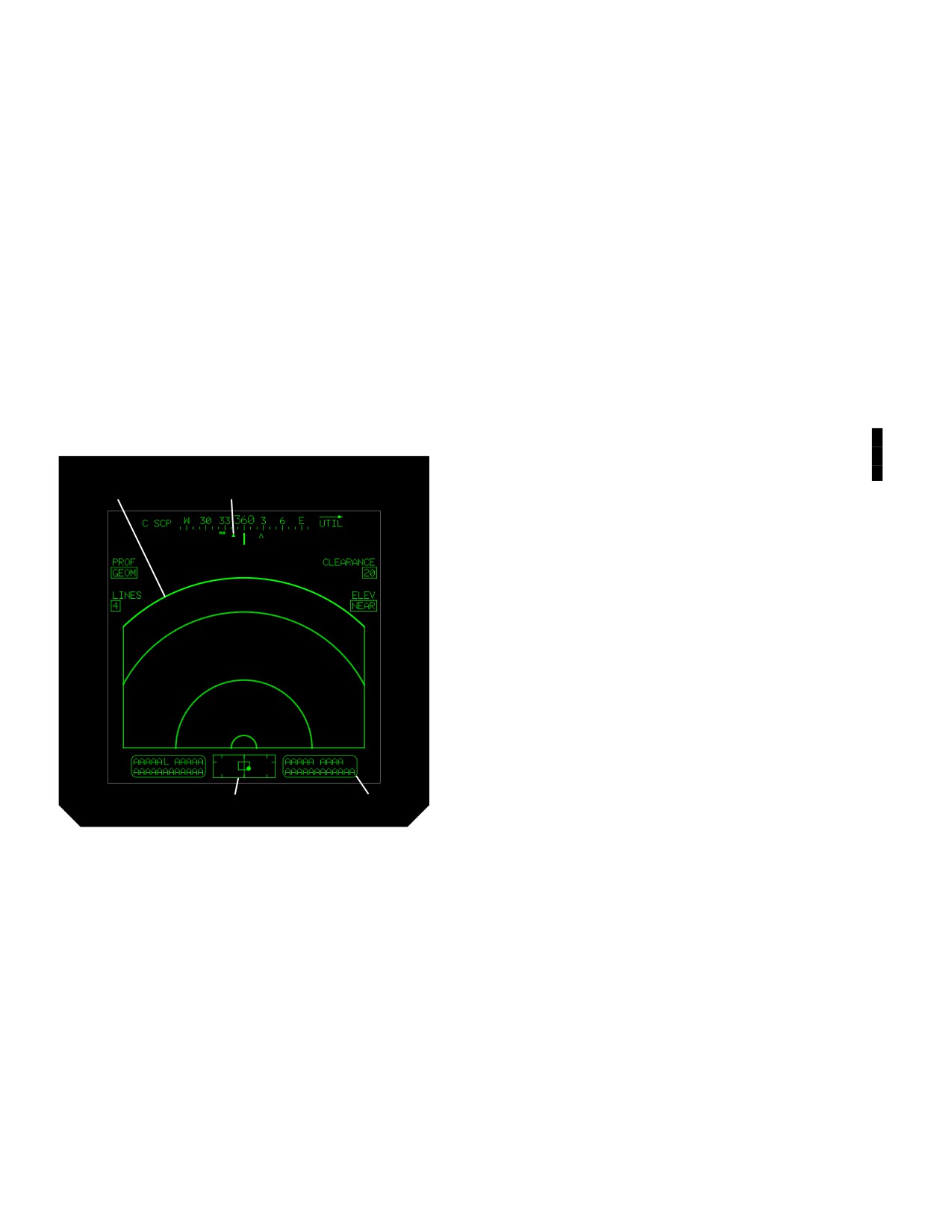
TM 1-1520-251-10
f. CLEARANCE Button. The CLEARANCE button
1. TPM Scan Sector Symbols. The scan sector
is used to select the clearance plane setting of the TPM.
symbology is displayed in full intensity and is
Selecting the CLEARANCE button will call up the clear-
based on the selected scan size: Wide or Nar-
ance plane setting options: 20, 50, 100, and 200. These
row. The format of the TPM sector is based on
values represent the number of feet below the helicopter
aircraft airspeed.
(wheels) at which the clearance plane exists.
2. Heading Scale and Symbols. The heading
g. ELEV Button. The FCR page ELEV button alter-
scale and associated symbols are as described
nately selects two different antenna elevation positions to
in chapter 2.
obtain the desired radar information. Pressing the ELEV
button to select FAR sets the antenna elevation at - 0.5° to
3. High Action Display. The High Action Display
give information for the earliest warning of high terrain out
is as described in paragraph 4.16.
to 2500m. Pressing the ELEV button to select NEAR sets
the antenna elevation at - 3° to measure terrain in rain or
4. FOR Symbols. The Field of Regard and
obtain radar information out to minimum range (approxi-
associated symbols are as described in para-
mately 1000m).
graph 4.14.
4.35.17 TPM Symbology. A view of the TPM Symbolo-
gy is shown in figure 4-51.
5. Total Obstacle Count Status Window. The to-
tal obstacle count status window appears when
obstacles are detected.
1
2
4
3
LBA2593A
Figure 4-51. TPM Symbology
Use or disclosure of this information is subject to the restriction(s) on the title page of this document.
4-48
Change 3
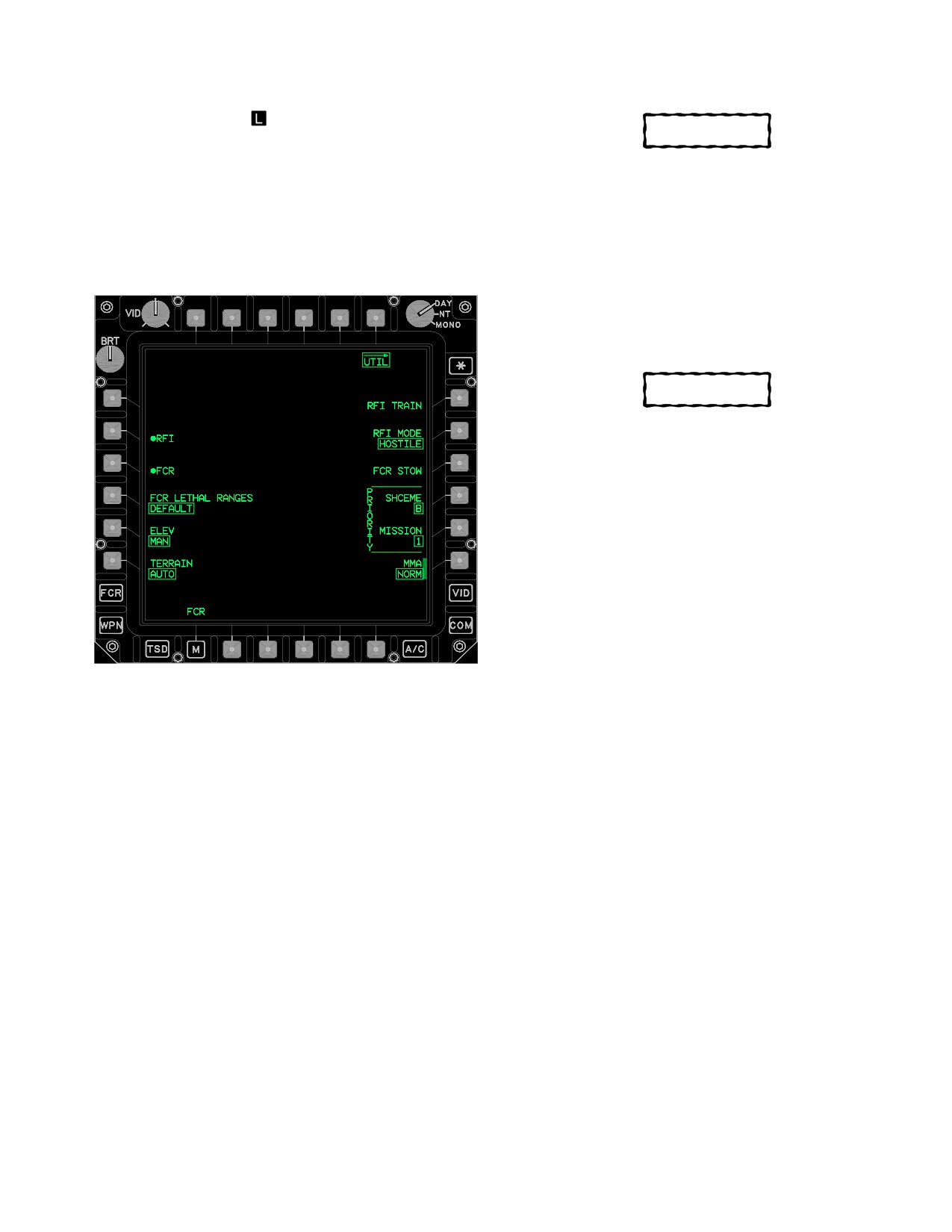
TM 1-1520-251-10
4.36 FCR UTIL PAGE
CAUTION
The FCR UTIL page (fig 4-52 ) is used to enable the FCR
Continued operation with the FCR TEMP
and RFI, override BIT, and set various FCR and RFI
ORIDE button selected may cause per-
modes. On initial aircraft powerup, the MMA button de-
manent damage to FCR components.
faults to the pinned position. Subsequent FCR powerup/
powerdown operations are conducted through the FCR or
4.36.1 FCR TEMP ORIDE Button. The FCR TEMP
WPN UTIL page.
ORIDE button is used to prevent overtemperature protec-
tion shutdown of the FCR when it has been detected in an
overtemperature state (FCR HOT). This button is dis-
played only when an overtemperature state has been de-
tected.
CAUTION
FCR BIT ORIDE selection in extreme cold
weather ( - 105 C or colder) could result in
damage to the FCR.
4.36.2 FCR BIT ORIDE Button. The FCR BIT ORIDE
button is used to override the FCR built-in-test sequence.
This button is displayed only when the FCR is in BIT.
4.36.3 FCR LETHAL RANGES Button. The FCR LE-
THAL RANGES button is used to select the desired lethal
ranges data to be used by the FCR for target classifica-
tion. Selecting the FCR LETHAL RANGES button alter-
nately toggles between DEFAULT and MODIFIED. The
default data file is resident in the FCR and the modified
LBA3009A
data file is available from the DTC (if programmed)
4.36.4 ELEV Button. The ELEV button is used to set
Figure
4-52.
FCR UTIL Page
the state of FCR antenna elevation control to AUTO. Se-
lecting the AUTO state automatically adjusts the elevation
value passed to it by the weapon processor for the given
acquisition LOS.
The FCR UTIL page provides the following unique selec-
tions:
4.36.5 RFI TRAIN Button. The RFI TRAIN button is
used to activate the training mode of the RFI subsystem.
• L1
FCR TEMP ORIDE button
Selecting the RFI TRAIN button modes the system to pro-
• L4
FCR BIT ORIDE button
vide an on - board emulation of RFI detected emitters for
aircrew training exercises. This is a contrived set of
• L4
FCR LETHAL RANGES button
threats preprogrammed solely for training purposes.
• L5
ELEV button
4.36.6 RFI MODE Button. Refer to Section III, para
• L6
TERRAIN button
4.90.8 for description.
• R1
RFI TRAIN button
4.36.7 FCR STOW Button. The FCR STOW button is
used to stow the FCR antenna.
• R2
RFI MODE button
4.36.8 SCHEME Button. The SCHEME button is used
• R3
FCR STOW button
to select the desired prioritization scheme to be used by
• R4
SCHEME button
the FCR for target classification. Selecting the SCHEME
• R5
MISSION button
button calls up options of A through G. Three priority
schemes are resident in the aircraft (FCR) and another 4
• R6
MMA button
are available from the DTC.
Use or disclosure of this information is subject to the restriction(s) on the title page of this document.
4-49