HELICOPTER, ATTACK, AH-64D LONGBOW APACHE. TECHNICAL MANUAL (2002) - page 11
TM 1-1520-251-10
4.36.9 Priority Scheme Selections. FCR target in-
ranges, if loaded, are selected using the FCR UTIL page
formation is prioritized by the FCR and used to direct the
FCR LETHAL RANGES button.
selected weapon against targets and to enhance situa-
4.36.11 MISSION Button. This button toggles between
tional awareness in the area of operations. Seven priority
1 and 2. It is used to determine which mission is used
schemes are used by the FCR; 3 schemes are resident in
when loading Priority schemes D through G. This load
the FCR (options A, B, and C), and 4 are available for
takes place when Priority schemes D through G are
loading via the DTC (options D through G) if programmed.
selected using the SCHEME button. This button will auto-
All priority schemes give higher priority to targets merged
matically switch to 1 or 2 when the Master, Mission 1, or
with RFI emitters and vary only with respect to how un-
Mission 2 ALL uploads are commanded.
merged targets are prioritized. Prestored FCR priority
schemes (A, B, and C) are summarized as follows:
4.36.12 TERRAIN Button. The TERRAIN button is
used to select the radar clutter threshold consistent with
a. Priority scheme A emphasizes airborne and sta-
anticipated terrain or other features in the area of opera-
tionary ground targets.
tions.
b. Priority scheme B emphasizes stationary ground
NOTE
targets.
In the Ground Targeting Mode (GTM) only,
c. Priority scheme C emphasizes airborne and mov-
selecting the reserved terrain selection en-
ing ground targets.
ables a Moving Target Indicator (MTI) only
mode in the FCR P8 software load and sub-
The 4 priority scheme options available for loading
sequent. The Stationary Target Indicator
through the DTC and are programmed into the DTC via
(STI) target detection processing is dis-
the AMPS. All 7 priority schemes, if loaded, are selectable
abled. This selection will cause an FCR fault
using the FCR UTIL page SCHME button.
message on the UFD/EUFD and an FCR
4.36.10 FCR Lethal Ranges Selections. FCR lethal
STI FAIL indication on the DMS page. To re-
range data is processed with with the selected priority
turn to STI detected targets, select any oth-
scheme to determine FCR target priority. One of two lethal
er terrain selection. The new selection will
range files is used by the FCR; one is resident in the FCR
take effect at the beginning of the next scan.
(DEFAULT file), and one is available for loading via the
4.36.13 Terrain Sensitivity Setting. The terrain sensi-
DTC (MODIFIED file) if programmed. The lethal range is
tivity setting is selectable using the FCR UTIL page TER-
the maximum effective range for the specific threat or tar-
RAIN SENSITIVITY button. This provides the crewmem-
get type and is used in the FCR prioritization algorithm to
ber the capability to select the proper radar clutter
determine if ownship is within lethal range of a given tar-
threshold setting for correct processing of STI detections.
get.
The crewmember has a choice of 8 selectable sensitivity
Like priority scheme options D through G, the modified le-
options that is consistent with the anticipated terrain or
thal ranges available for loading through the DTC are pro-
other features in the area of operation, These selectable
grammed into the DTC via the AMPS. Modified lethal
options are found in table 4-19.
Table 4-19. Terrain Sensitivity Settings
OPTION
TERRAIN SELECTION
AUTO
FCR automatically selects terrain.
RESERVED
In the FCR P7 software load and previous, selecting RESERVED, the FCR automatically se-
lects terrain and false alarm control (Pd is not assured). In the FCR P8 software load and sub-
sequent, selecting the RESERVED, enables the MTI only mode and disables the STI.
1
Eastern U.S. coastal plains region.
2
Valleys, mountains, sparse trees.
3
Combination of coastal plains and desert (light vegetation).
4
Similar to setting 3 with different decision thresholds.
5
Desert vegetation and arroyos (water carved gully or channel).
6
Similar to setting 5 with sparse vegetation.
Use or disclosure of this information is subject to the restriction(s) on the title page of this document.
4-50
Change 3
TM 1-1520-251-10
4.37 FCR OPERATION
4.39 FCR SYSTEM STATUS
In certain cases, status windows are displayed on the
FCR page and the FCR UTIL page when the FCR is in
The FCR, in combination with the RF missile, provides a
other than a ready state:
fire-and-forget capability. An integrated mast-mounted
RFI provides threat emitter warning and azimuth direction
FCR NOT INSTALLED
The FCR is not installed.
finding/cueing. RFI detected emitter signals may be corre-
lated with FCR target data to derive the identity and loca-
FCR NOT POWERED
The FCR is set to OFF.
tion of a particular threat. Target information is sent to the
FCR BIT
The FCR is performing
weapons processor for the determination of target loca-
IN PROGRESS
BIT.
tion coordinates and is used to direct the selected weapon
FCR FAIL
The FCR has been de-
against targets. FCR target information is displayed on
tected as failed.
the FCR page targeting format and the TSD page. The
FCR ZEROIZED
The FCR has been de-
FCR page targeting format may also be displayed on the
tected as zeroized.
ORT HOD/HDD. In addition, the information is processed
for the generation of FCR target symbology for overlay
4.40 IDM STATUS
onto TADS/PNVS sensor video.
Status windows are also displayed on the FCR page and
the FCR UTIL page when certain IDM transmissions are
4.38 FCR PAGE CONTROLS
received:
RF HANDOVER Valid RF handover target has
been received and accepted.
FCR page controls are dependent upon the states of the
sight select function and of the FCR mode function. The
IDM TARGET
Valid FCR target has been re-
following is a general description of controls available:
DATA
ceived and accepted for display.
4.41 FCR MODES OF OPERATION
• When the FCR is not the selected sight in either
crew station, selecting the FCR subsystem bezel
The FCR is employed in one of three operational modes
button or the FCR page button from the MENU
to perform ground targeting (GTM and RMAP), air target-
page calls up the FCR page in the format as last
ing (ATM), and terrain profiles mode (TPM). Modes are
selected at the FCR mode switch (in either crew
selected using the FCR mode switch on the LHG or col-
station).
lective mission grip. Momentarily positioning the FCR
mode switch to RMAP, after RMAP is initially selected,
• Selecting the sight select switch to FCR esta-
displays target symbols without radar video. GTM is the
blishes control of the FCR to that crew station in
FCR default mode. The last-to-select rule remains in ef-
the mode/format last selected at the FCR mode
fect for the mode switch. Radar clutter threshold, that is
switch (from either crew station). If the FCR page
consistent with the anticipated terrain or other features in
is not currently displayed on either MPD or the
the area of operation, is selected using the FCR UTIL
ORT HOD/HDD (CPG station) or TDU (CPG
page TERRAIN sensitivity button.
station), it is automatically called up on the left
MPD (in that crew station). All controls are
4.41.1 FCR Ground Targeting. Ground targeting is ac-
available. Sight selection of the FCR between the
complished using one of two modes: the Ground Target-
crew stations is based on last-to-select logic.
ing Mode (GTM) or the Radar Map (RMAP). These
ground scan modes are used to detect, classify and priori-
tize both moving and stationary ground targets and low
• When the FCR is the selected sight in the opposite
flying air targets. Targets are presented on the targeting
crew station, selecting the FCR subsystem bezel
format at the current range/azimuth location.
button or the FCR button from the MENU page
calls up the FCR page in the format as last
4.41.2
FCR Air Targeting. Air targeting is accom-
selected at the FCR mode switch (in either crew
plished using the ATM. It is an air scan mode used to de-
station). Only the FCR UTIL page button, the TGT
tect, classify and prioritize air targets. Targets are pres-
button (and associated controls) and the ACQ
ented on the FCR targeting format at the current
button is available.
range/azimuth location.
Use or disclosure of this information is subject to the restriction(s) on the title page of this document.
Change 3
4-51
TM 1-1520-251-10
used in conjunction with a terrain profiles format displayed
WARNING
with IHADSS video.
The terrain profiling mode of the FCR
shall not be relied upon for primary pilot-
WARNING
age information.
Low radar cross section objects such as
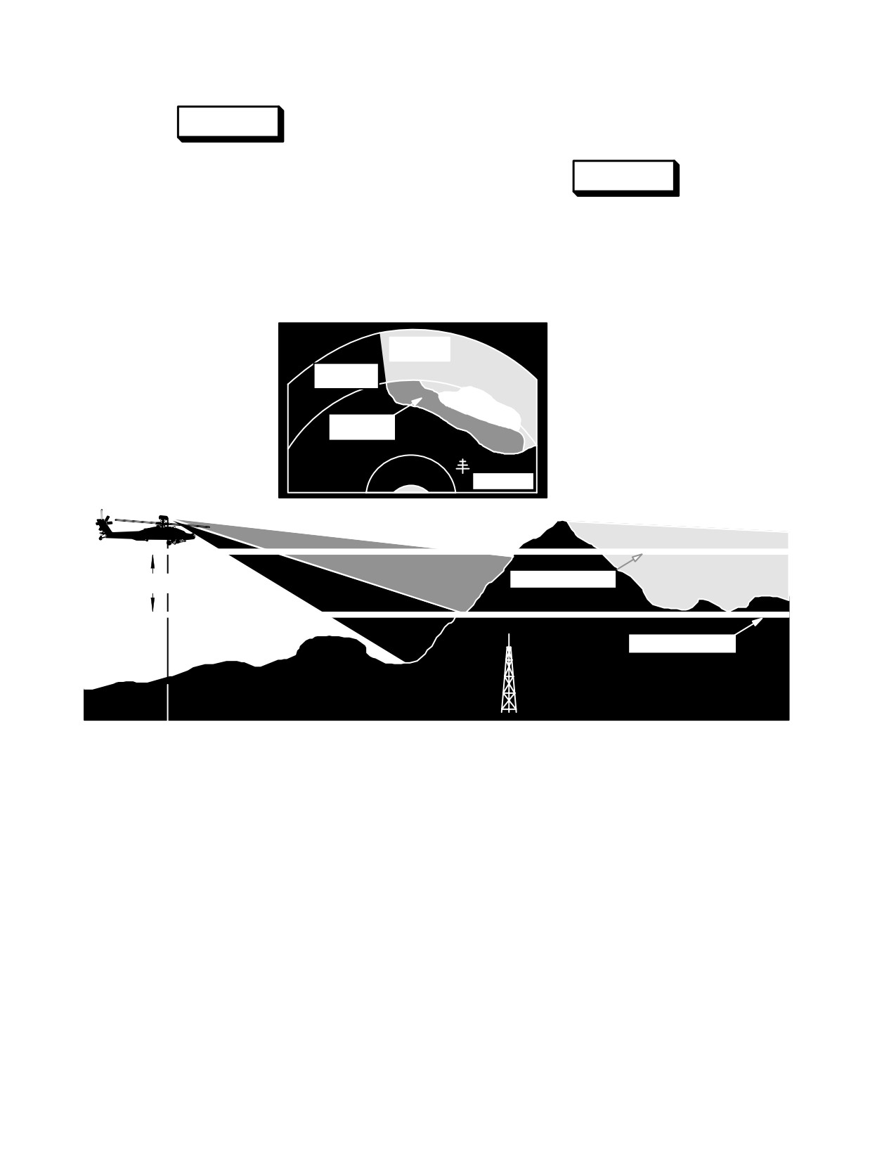
4.41.3 FCR Terrain Profiles. Terrain clearance is ac-
telephone or power poles or isolated
complished using the TPM. It is a ground scan mode used
leafless trees cannot be accurately mea-
to provide pilotage information to either the pilot /CPG. It
sured by the FCR. The clearance plane
provides an FCR sector ground clearance plane format
should be set to exceed the height of all
displayed (fig 4-53) on an MPD or ORT display which is
anticipated hazards.
ÓÓÓÓÓÓÓÓÓ
ÓÓÓÓÓÓÓÓÓÓÓÓ
LIGHT GRAY
ÓÓÓÓÓÓÓÓÓ
UNKNOWN
ÓÓÓÓÓÓÓÓÓÓÓÓ
BLACK SAFE
ÓÓÓÓÓÓÓÓÓ
TO FLY
ÓÓÓÓÓÓÓÓÓÓÓÓ
ÓÓÓÓÓÓÓÓÓ
WHITE
ÓÓÓÓÓÓÓÓÓÓÓÓ
HAZARDOUS
ÓÓÓÓÓÓÓÓÓ
DARK GREY
ÓÓÓÓÓÓÓÓÓÓÓÓ
SOME RISK
ÓÓÓÓÓÓÓÓÓ
ÓÓÓÓÓÓÓÓÓÓÓÓ
ÓÓÓÓÓÓÓÓÓ
ÓÓÓÓÓÓÓÓÓÓÓÓ
OBSTACL
ÓÓÓÓÓÓÓÓÓ
E
ÓÓÓÓÓÓÓÓÓÓÓÓ
ÓÓÓÓÓÓÓÓÓÓÓÓÓÓÓÓÓÓÓÓÓÓÓÓÓÓÓÓÓÓÓÓÓ
ÓÓÓÓÓÓÓÓÓÓÓÓÓÓÓÓÓÓÓÓÓÓÓÓÓÓÓÓÓÓÓÓÓ
ÓÓÓÓÓÓÓÓÓÓÓÓÓÓÓÓÓÓÓÓÓÓÓÓÓÓÓÓÓÓÓÓÓ
ÓÓÓÓÓÓÓÓÓÓÓÓÓÓÓÓÓÓÓÓPRESENT ALTITUDEÓÓÓÓÓÓÓÓÓ
20, 50, 100, 200 FT
ÓÓÓÓÓÓÓÓÓÓÓÓÓÓÓÓÓÓÓÓÓÓÓÓÓÓÓÓÓÓÓÓÓ
ÓÓÓÓÓÓÓÓÓÓÓÓÓÓÓÓÓÓÓÓÓÓÓÓÓÓÓÓÓÓÓÓÓ
CLEARANCE PLANE
ÓÓÓÓÓÓÓÓÓÓÓÓÓÓÓÓÓÓÓÓÓÓÓÓÓ
ÓÓÓ
ÓÓÓÓÓÓÓÓÓÓÓÓÓÓÓÓÓÓÓÓÓÓÓÓÓÓÓÓÓÓÓÓÓ
ÓÓÓÓÓÓÓÓÓÓÓÓÓÓÓÓÓÓÓÓÓÓÓÓÓÓÓÓÓÓÓÓÓ
ÓÓÓÓÓÓÓÓÓÓÓÓÓÓÓÓÓÓÓÓÓÓÓÓÓÓÓÓÓÓÓÓÓ
LBA2585
ÓÓÓÓÓÓÓÓÓÓÓÓÓÓÓÓÓÓÓÓÓÓÓÓÓÓÓÓÓ
Figure 4-53. FCR Terrain Profiles
a. Clearance Planes. Options of 20, 50, 100, or
• DARK GRAY represents an area that is potentially
200 feet below the helicopter wheels are available for
hazardous and does not guarantee the expected
selection. Four shades of gray will be displayed to repre-
clearance. Terrain measured is between the
sent terrain information as follows:
helicopter present altitude and the clearance
plane. Flying into a dark gray area presents some
• LIGHT GRAY represents unknown terrain. Terrain
risk depending on TADS/PNVS video quality.
has areas in radar shadow or areas where
sufficiently accurate measurements CANNOT be
• BLACK represents terrain measured below the
made. This can occur in a ring near the radar or in
selected clearance plane.
a ring where ground cannot be reached at the
• WHITE represents a hazardous area that must be
radar slant range. A light gray area without a
avoided. Terrain measured is above the helicopter
characteristic shadow edge can be an indication of
wheel height.
heavy rain or low reflectivity terrain. The FCR is
capable of detecting and reporting heavy rain.
However, there is no discrete symbology for this
information.
Use or disclosure of this information is subject to the restriction(s) on the title page of this document.
4-52
TM 1-1520-251-10
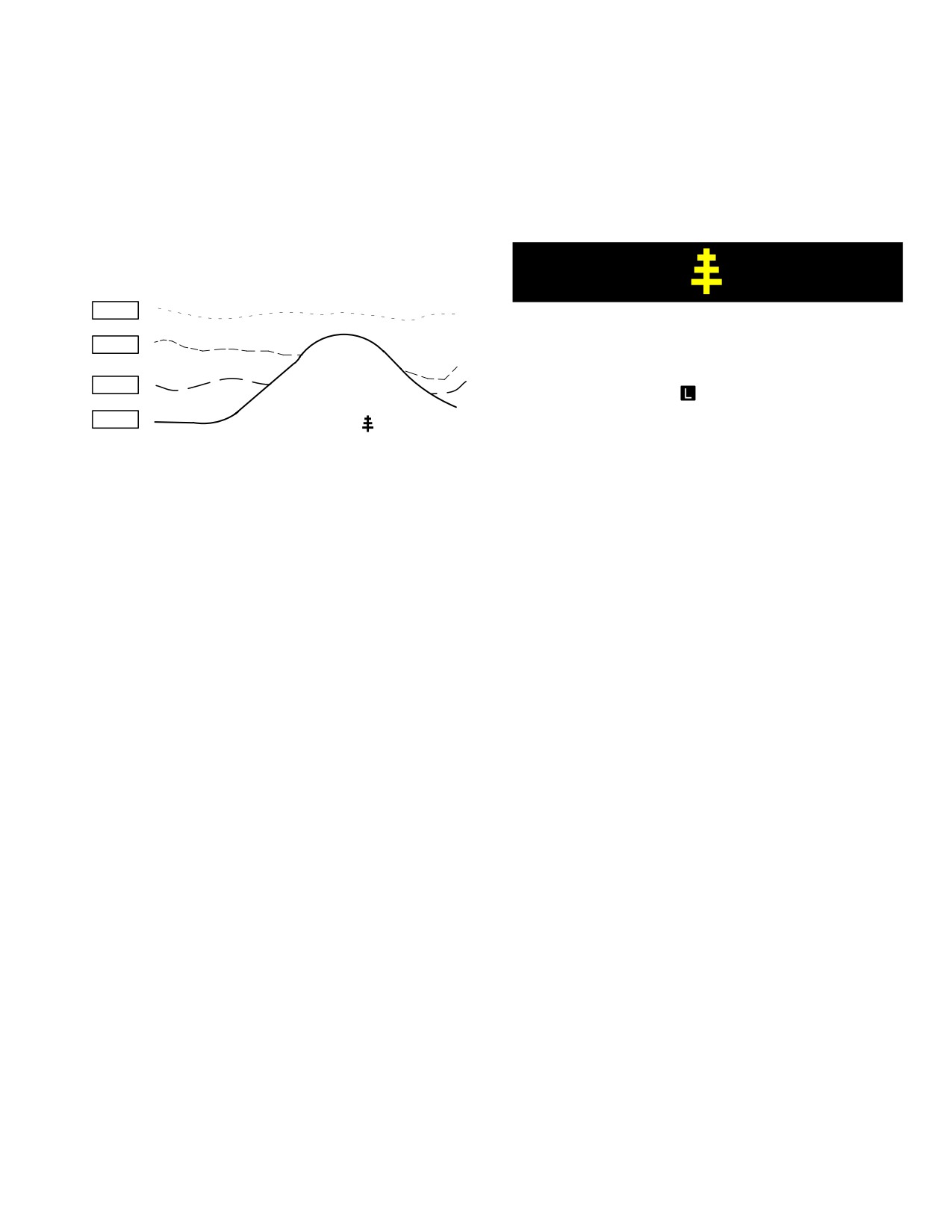
b. Profile Lines. Terrain profile data (fig. 4-54) is
symbols are not displayed in a wiper fashion as with tar-
collected in range intervals that are based on the FCR
geting data. The symbols are displayed at one time each
page profile (PROF) button selection. The highest eleva-
time the data is updated at the completion of a TPM scan.
tion points within a range interval are detected and com-
TPM obstacle symbols are displayed in YELLOW. A maxi-
bined into a single profile line. FCR page range interval
mum of 64 symbols may be displayed on the FCR page
selections are geometric (GEOM), arithmetic (ARITH), or
TPM format or IHADSS C - Scope formats at any one time.
TEST. The number of profile lines displayed can be se-
lected using the FCR page LINES button. Selecting the
LINES button will display options; 1, 2, 3, and 4.
LINE 4
LBA2566
LINE 3
Figure 4-55. TPM Obstacle Symbol
LINE 2
4.42 FCR FUNCTIONS
LINE 1
OBSTACLE SYMBOL
LBA2595
4.42.1 FCR Scan Size. The FCR scan size default is
wide for all targeting modes. If a new scan size is se-
Figure 4-54. Terrain Profile Data
lected, the new scan size selection will be used at the be-
ginning of the next scan. In TPM, the FCR determines
scan size based on helicopter ground speed. In cued
Lines and obstacles are displayed as follows:
search, the FCR determines scan size based on the des-
ignated emitter frequency and whether the emitter was
detected in the coarse or fine area of coverage.
Option 0
Display obstacles only
Option 1
Display line 1 with obstacles
4.42.2 FCR GTM/RMAP Scan. Characteristics of an
Option 2
Display lines 1 and 2 with obstacles
FCR scanburst depend on the type of scanburst (single or
Option 3
Display lines 1, 2, and 3 with obstacles
continuous) and the selected scan size. Scan bursts also
use multiple detections of moving targets to calculate
Option 4
Display lines 1, 2, 3, and 4 with obstacles
cross range velocity.
Range interval settings are:
a. Single Scanburst. When the FCR scan switch is
momentarily positioned to S-SCAN the FCR will complete
GEOM
Line 1
100 - 300 meters
a single scan or, based on the selected FCR scan size, a
Line 2
300 - 500 meters
scanburst. If the FCR scan switch is momentarily posi-
Line 3
500 - 1000 meters
tioned to S-SCAN or C-SCAN before the scanburst is
Line 4
1000 - 2500 meters
complete, the FCR will stop the scan, deactivate the trans-
ARITH
Line 1
100 - 700 meters
mitter, and return the FCR antenna to the azimuth start
Line 2
700 - 1300 meters
position for the selected mode and scan size. In GTM, a
Line 3
1300 - 1900 meters
near bar and a far bar equals one scan. A single scanburst
Line 4
1900 - 2500 meters
consists of multiple scans, based on the selected scan
size, as listed below:
TEST
Line 1
500 meters
Line 2
1000 meters
Line 3
1500 meters
Scan Size Number of Scans Per Scanburst
Line 4
2000 meters
Wide
2
Medium
2
4.41.4
TPM Obstacle Symbol. The TPM obstacle
Narrow
3
symbols represent objects or terrain features which the
FCR has derived as obstacles to flight (fig 4-55). These
Zoom
4
Use or disclosure of this information is subject to the restriction(s) on the title page of this document.
4-53
TM 1-1520-251-10
b. Continuous Scanburst. When the FCR scan
b. RMAP Wiper Symbol. In the RMAP format, the
switch is momentarily positioned to C - SCAN, the FCR will
scan wiper symbol is displayed as a vertical line and
start a continuous scanburst. Continuous scanburst ap-
moves left to-right-covering the near bar and right - to - left
pears as a series of scanburst. The FCR will continue to
covering the far bar.
scan until the FCR scan switch is momentarily positioned
to C - SCAN or S - SCAN again. When the continuous
c. Near Bar/Far Bar. A bar (sweep) is the move-
scanburst is deactivated, the MMA is returned to the start
ment of the radar from one scan limit to the other. The
position for the selected mode and scan size.
near bar begins on the left limit of the scan width and
sweeps left-to-right through the search area to the right
limit. The antenna, during turnaround, adjusts elevation
4.42.3 FCR Display Zoom. Targeting information for
up for far bar and sweeps right-to-left through the search
any scan size can be viewed at approximately 6:1 zoom
area to the left limit. This completes 1 scan. The radar
display ratio. The border of the zoomed format is dis-
beamwidth in the near bar overlaps the beamwidth of the
played in WHITE.
far bar. Targets in the overlap area will be scanned twice
during a single radar scan. This provides the FCR with
a. RHG ZOOM Switch. If zoom is selected by
more information to be used during the classification/
pressing the RHG ZOOM switch, the display zoom area
prioritization process and improves PD.
will be centered on the NTS target. The ZOOM button will
not select zoom if there is no NTS target.
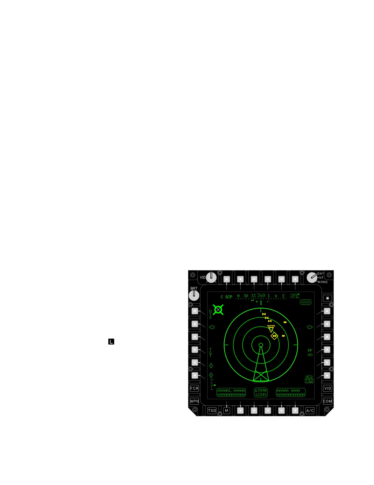
d. Blanking Symbol. The FCR blanking symbol (fig
4-56) is displayed within the selected scan sector to indi-
cate that the FCR transmitter has been set to OFF for sys-
b. FCR Page ZOOM Button. If zoom is selected
tem calibration or to avoid scanning directly toward the
using the FCR page ZOOM button, the LHG or collective
vertical stabilizer and tailboom. Each side of this polygon
mission grip CURSOR control is used to select the area to
is made up of azimuth lines where blanking begin and
be displayed. When the display cursor is positioned within
where blanking ends. The remaining lines of the polygon
the FCR target area, the display cursor symbol is changed
connect the line end points at the maximum and minimum
to a WHITE zoom area box with corner to corner cross-
azimuth lines. Two additional criss-crossing lines are dis-
hairs. The size of the zoom area box is determined by the
played in the last 30% of the polygon to form a large “X”
selected scan size. If the zoom area box is moved within
symbol.
the area of active button selections, the zoom area box
will change to the normal display cursor symbol and cur-
sor enter operation. Pressing the LHG or collective mis-
sion grip CURSOR control or RHG cursor enter switch will
enter the cursor selection and the display will zoom on the
designated area. Geometric fidelity with respect to relative
target positions (and radar video in RMAP format) is re-
tained in the zoom area format. Deselecting zoom using
the FCR page ZOOM button will return the FCR to the last
selected format.
4.43 FCR PAGE SYMBOLOGY
4.43.1 Scan Wiper Symbol. A scan wiper symbol is
displayed within the scan sector on the FCR page when
the FCR is transmitting. It is displayed in WHITE during
single scan bursts and in GREEN during continuous scan.
a. GTM Wiper Symbol. In the GTM PPI format, the
scan wiper symbol is displayed as a line and moves right-
to-left covering the near bar and left-to-right covering the
LBA2586A
far bar. The line appears to move or wipe across the scan
sector pivoting about the sector origin in conjunction with
the actual radar antenna movement.
Figure
4-56.
FCR Blanking Symbol
Use or disclosure of this information is subject to the restriction(s) on the title page of this document.
4-54
TM 1-1520-251-10
e. ATM Wiper Symbol. In ATM PPI format, the
Target symbols appear virtual in position on the display as
scan wiper symbol appears to move or wipe across the
the selected sensor is moved about. Only those symbols
sector scan, pivoting about the center of the sector, with
within the sensor FOV will appear on the format.
FCR antenna movement. During continuous scanning,
the wiper symbol moves back and forth across the scan
sector until the FCR is commanded to stop scanning. This
symbol is visible in ATM and GTM/RMAP.
f. TPM Wiper Symbol. In TPM PPI format, the
scan wiper symbol appears to move or wipe across the
sector scan, pivoting about the center of the sector, with
FCR antenna movement. As it reaches the right boundary
of the selected scan sector it moves back toward the left
boundary of the scan sector and continues to cover the
entire area in front of the helicopter.
4.43.2 ATM Centerline Symbol. The FCR centerline
symbol for ATM is a partial intensity line displayed, when
medium, narrow, or zoom scan sizes are selected, within
the ATM format. The centerline symbol is not displayed
when wide scan is selected. It is a partial intensity line
which extends from the first range arc to the outer range
arc of the selected scan size. The FCR centerline symbol
is dynamic and represents the relative FCR centerline
position within the ATM format.
LBA2600A
4.44 FCR TARGET INFORMATION
FCR target information is prioritized by the FCR and used
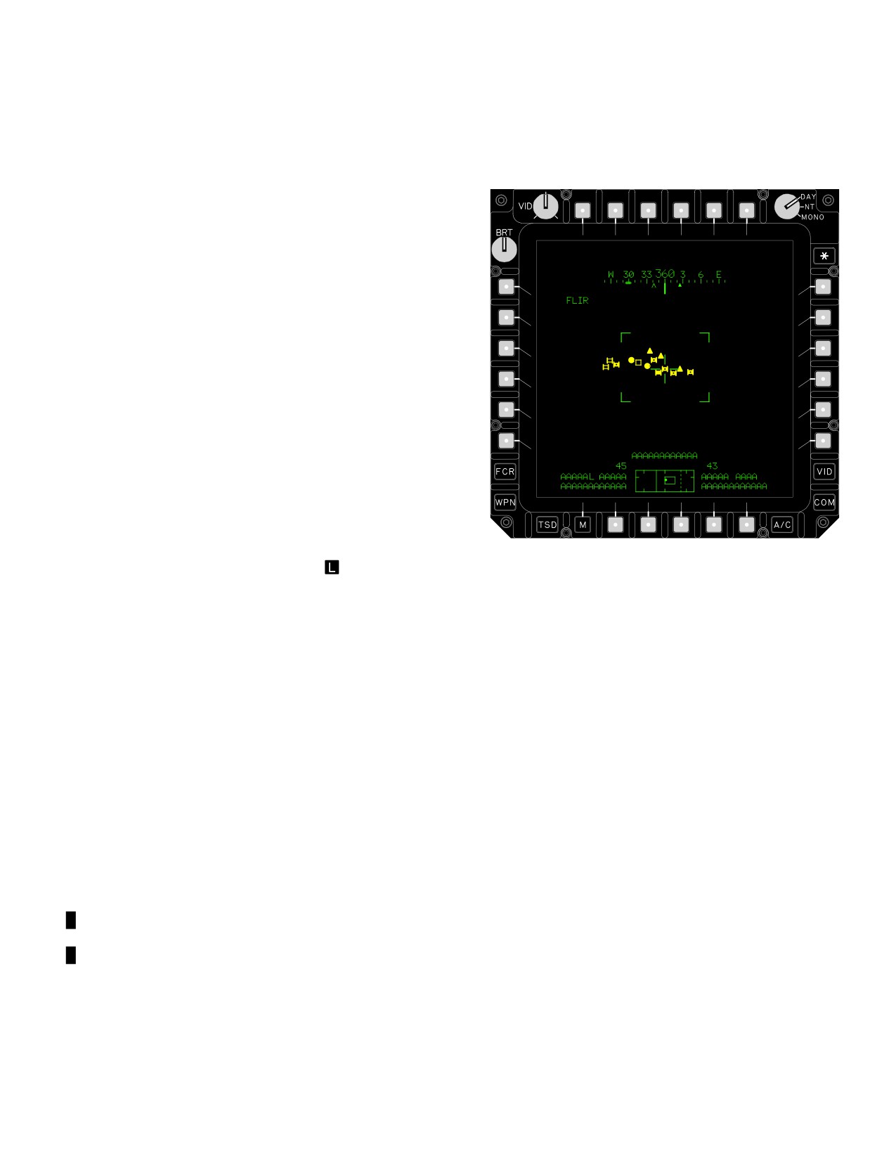
Figure
4-57.
C-Scope Presentation on Weapons
to direct the selected weapon against targets. Seven
Symbology
priority schemes are used by the FCR: 3 schemes are res-
ident in the FCR (options A through C), 4 are available
from the DTC (options D through G). The information can
4.44.2 GTM Target Processing/Prioritization. GTM
be processed for FCR target symbology overlay on flight
target symbols are displayed in any given scanburst. Tar-
and weapon symbology formats with the C-SCP se-
get data is correlated from scan-to-scan during a scan-
lected. When FCR target data is displayed, switching from
burst to derive priority target characteristics (velocity and
RMAP to GTM will display information in the selected for-
classification). Scan-to-scan correlation improves STI
mat. Selecting ATM or TPM will eliminate all ground tar-
detection and classification and Moving Target Indicator
geting data. Eliminated ground targeting data cannot be
(MTI) classification. Scan-to-scan correlation is also used
recalled for display. All target information is sent to the dis-
to measure cross range velocity, and differentiate cross
play processor for target symbology presentation on the
range moving targets from stationary targets. When a new
FCR page (highest priority) or TSD (all targets).
scan is commanded, the FCR will clear its target file. Tar-
get types and location which are not stored in the threat
4.44.1 C-SCOPE Processing. FCR target symbology
file are lost. If single scan is selected, targets are corre-
is processed for overlay on the TADS/PNVS video by se-
lated from scan-to-scan but not from scanburst-to-scan-
lecting the FCR page C-SCOPE (fig 4-57) or by pressing
burst. As soon as a new scanburst is initiated, the priority
the RHG C-SCOPE switch. GTM and ATM provide a tar-
and total target lists and total target count are cleared, re-
get symbol overlay display on TADS/PNVS video in C -
initiated, and updated during the scan. In continuous
scope format on the IHADSS, ORT or TDU. Target sym-
scan, targets are correlated from scan-to-scan and from
bols are displayed in geometric fidelity over sensor video.
scanburst-to-scanburst.
Use or disclosure of this information is subject to the restriction(s) on the title page of this document.
Change 3
4-55
TM 1-1520-251-10
4.44.3 Scanbursts. The processing and display of tar-
• Priority target data is correlated from scanburst to
get data is unique to the type of scanburst, single or con-
scanburst.
tinuous. The scan burst supports scan-to-scan correlation
• NTS is displayed at the end of the first scan and is
without appreciably increasing timelines. Scan-to-scan
updated by the WP as target information is
correlation is a process which maintains track of detected
prioritized by the FCR.
targets between each scan. Correlating a burst of scans
while keeping the timelines short is referred to as a single
• To avoid re-engagement, shot-at target data is
scanburst operation. Continuous scanburst operation pro-
tagged.
vides various scan-to-scan correlations.
•
Stationary target symbols are added and updated
for classification during the final scan. Threats are
a. Single Scanburst.
added during any scan.
• Priority target data, total target count, total targets,
• Targets blank as they exit the scan sector except
and map are purged at the start of each single
for the NTS. NTS will become dashed and partial
scanburst and updated during the scanburst.
intensity when NTS is at the edge of sector scan
(crew member may select new NTS).
• Radar video is generated on the first scan in a
wiper fashion.
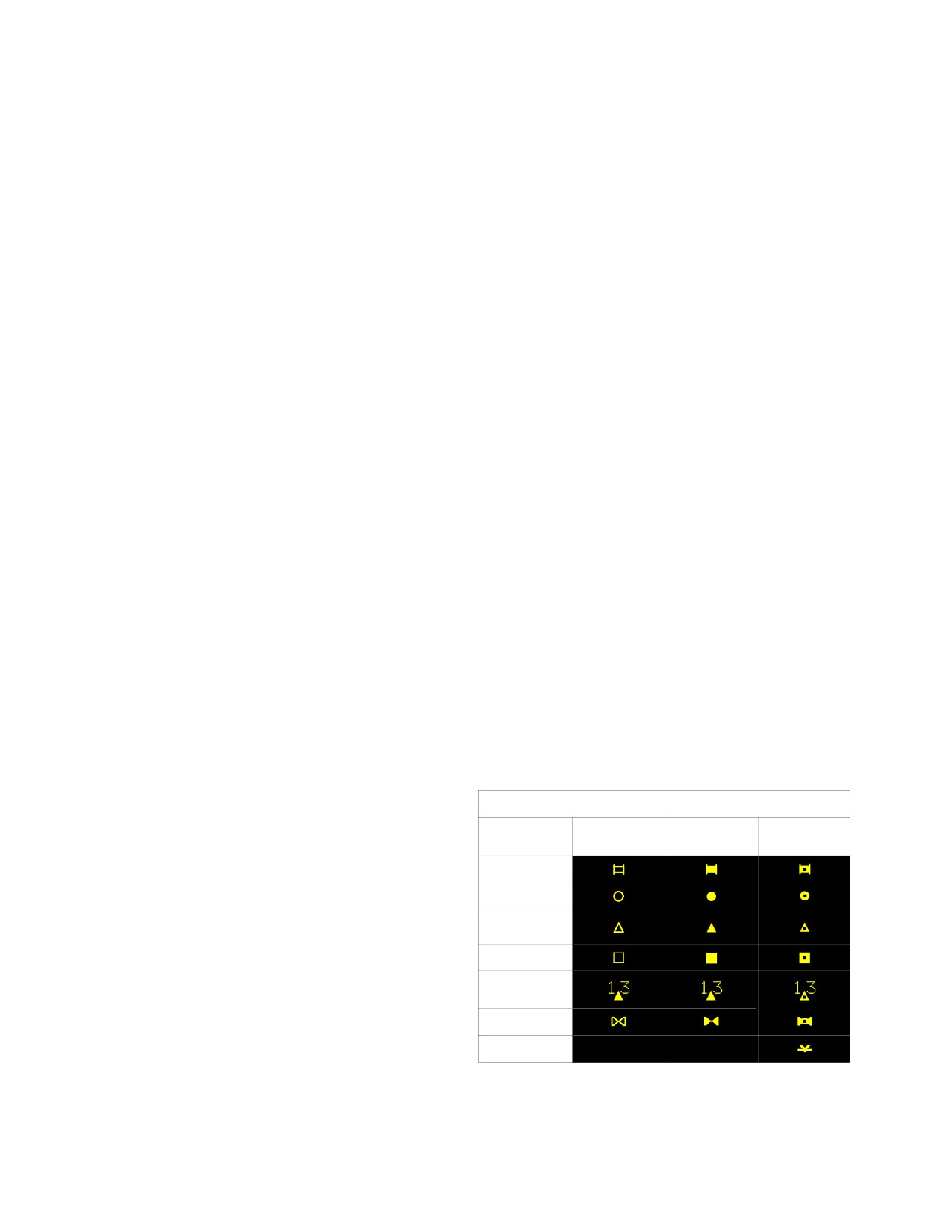
4.44.4 FCR Target Symbols. A maximum of 16 FCR
• Priority target data is correlated from scan to scan.
target symbols (fig 4-58) are displayed in any given scan.
These symbols represent the highest priority targets de-
• NTS is displayed at the end of the first scan and is
tected and classified for that scan or scan burst. Target
updated by the WP as target information is
data is correlated from scan to scan during a scanburst to
prioritized by the FCR.
derive priority target characteristics (velocity and classifi-
cation). Symbols are displayed in YELLOW by type target,
• To avoid re-engagement, shot-at target data is
type of anticipated missile launch (LOAL or LOBL), and a
tagged.
condition of moving or stationary. RFI detected emitters
• Stationary target symbols are displayed on the first
which have been correlated with radar target information
scan, added during intermediate scans (threats
is displayed by class and type within the scan sector of the
added), and updated for classification during the
format to indicate the threat/target location. Target sym-
final scan.
bols are dimmed after a period of time to indicate that the
target data is stale. Moving target symbols become stale
• Symbols are displayed in a wiper fashion during
after 5 seconds and stationary target symbols become
the first and last scan of a scanburst. During
stale after 30 seconds. Low priority targets are displayed
intermediate scans, only changes are displayed in
in partial intensity YELLOW on the TSD page as a half-
azimuth order.
size icon.
• Moving target symbols are displayed on the first
scan and updated for classification during the final
FCR TARGET SYMBOLS
scan. Moving air defense units will always be
LOAL
LOBL
LOBL
displayed.
(STATIONARY
(MOVING
)
)
• RFI target merges are displayed during any scan.
TRACK
WHEEL
b. Continuous Scanburst, first scan. Target data
AIR DEFENSE
is displayed essentially the same as during a single scan-
UNIT
burst.
UNKNOWN
MERGED
c. Continuous Scanburst, subsequent scans:
AIR DEFENSE
• Priority target data, total target count and total
HELICOPTER
targets are purged at the start of each scanburst
FLYER
and updated during the scanburst.
LBA2012
• Radar video is generated on the first scan in a
wiper fashion.
Figure 4-58. FCR Target Symbols
Use or disclosure of this information is subject to the restriction(s) on the title page of this document.
4-56
TM 1-1520-251-10
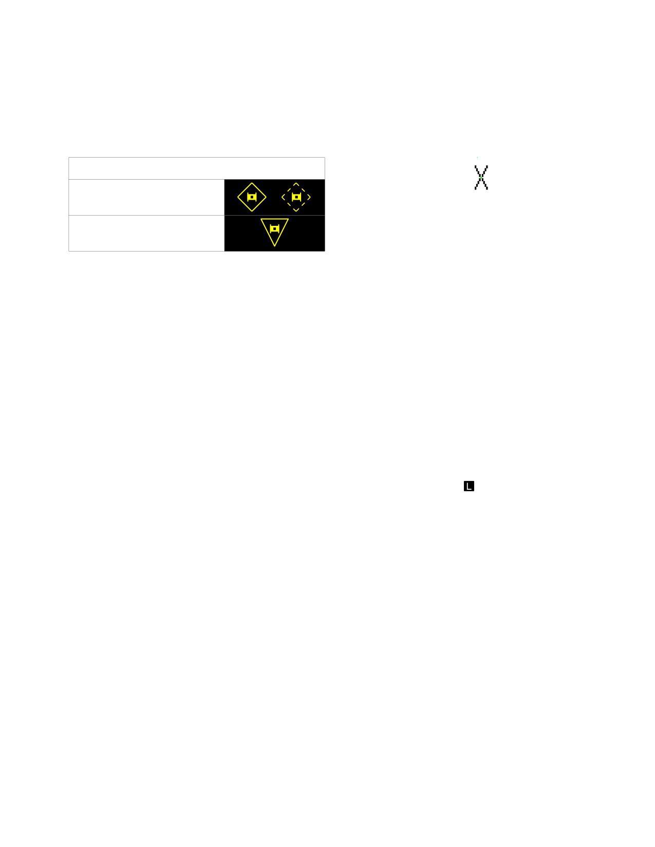
4.44.5 Priority of Fire Symbols. Unique symbols (fig
• The symbol is displayed beneath target symbols
4-59) are designated to indicate the 2 highest priority tar-
during/after a scan burst and prior to a Hellfire
gets: the NTS target and the alternate next-to-shoot
missile launch.
(ANTS) target. FCR priority of fire indicators include the
• The symbol is displayed on top of a target symbol
NTS symbol and the ANTS symbol.
following a Hellfire missile launch at that target.
PRIORITY OF FIRE INDICATORS
NEXTTOSHOOT
LBA2567
(#1 PRIORITY TARGET)
Figure 4-60. Shot - At Symbol
ALTERNATE
(#2 PRIORITY TARGET)
4.44.7 Priority Fire Zone Symbol. Priority fire (PF)
LBA2013
zones are displayed in WHITE as a convex or concave
quadrilateral to indicate a geographic area in which target
priority is established as highest for the processor prioriti-
Figure 4-59. NTS/ANTS Symbols
zation and display. It will be displayed in the GTM mode
(not presented in the RMAP mode). Only 1 PF zone will be
a. NTS Symbol. The NTS symbol is displayed in
active and displayed at a time as selected by the crew-
YELLOW around the highest priority target symbol within
member. This zone is constructed on the TSD page and
the sector scan to indicate the most significant target or
displayed on the FCR page (described in chapter 3).
threat information derived by the FCR. It will be initially
displayed at the completion of the first scan of a scan
4.44.8 No Fire Zone Symbol. No fire (NF) zone is dis-
burst. In addition, it is displayed around a priority target
played in YELLOW as a convex or concave quadrilateral
symbol as selected by the crewmember. The symbol is a
to indicate a geographic area in which target priority is es-
dashed symbol when the crewmember has not actioned a
tablished as prohibited for the processor prioritization and
weapon system. When FCR is the selected sight and the
display. Only 1 NF zone will be active and displayed at a
weapon system is actioned, the NTS target is frozen and
time as selected by the crewmember. This zone will be
the NTS symbol will become solid.
constructed on the TSD page and displayed on the FCR
page (described in chapter 3).
b. ANTS Symbol. The ANTS symbol is displayed in
4.45 RFI OPERATION
YELLOW concurrently with the NTS symbol to indicate
the alternate NTS target, or #2 priority target in the auto-
RFI targeting is accomplished using the GTM, RMAP, and
matic target selection sequence. The ANTS target is up-
ATM modes. It occurs through the normal employment of
dated at the end of each far bar and is not frozen, i.e., may
the FCR or by performing a cued search.
change as per the selected priority scheme algorithm.
Once the NTS target is frozen, and a target is detected
4.45.1 Normal FCR Modes. RFI targeting data is pro-
that out - prioritizes the NTS target, the ANTS symbol will
cessed and displayed as part of the normal operation of
be automatically displayed on that target symbol and flash
any FCR targeting mode. Uncorrelated RFI threat (out-
for 3 seconds. The operator may select the ENTER func-
side FCR search area or not merged with a candidate
tion to choose this target as the NTS. If the operator has
FCR target) symbols are displayed, in azimuth, on the out-
not selected ENTER at the 3 second time limit, the ANTS
er periphery of FCR GTM and ATM modes described
symbol will remain over the target as it has become the
above. RFI symbols are displayed in full intensity during
new ANTS target.
the period when the RFI emitters are active. RFI symbols
will be displayed in partial intensity after the emitters be-
4.44.6 Shot-At Symbol. The shot - at icon (fig 4-60) is
come inactive. The highest priority threat symbol, or #1
displayed within the selected scan sector to indicate the
emitter as determined by the system, is displayed in con-
locations at which Hellfire missiles have been launched
junction with the RFI Box symbol. RFI emitters, detected
(actual or simulated) by the ownship or received IDM
within the fine coverage area of the RFI antenna, will be
BDA. Shot at target data is stored to the shot target file for
displayed by emitter type modifier symbol. RFI emitters
display on the TSD page as described in chapter 3 and for
detected within the coarse coverage area of the RFI an-
display on the FCR page. This icon provides shot-at in-
tenna will be displayed by the type modifier number. Cor-
formation for two situations on the FCR page.
related threats are displayed within the selected format
Use or disclosure of this information is subject to the restriction(s) on the title page of this document.
4-57
TM 1-1520-251-10
scan sector by class and type and threat/target location.
Status Field of the HAD for a minimum of 10 seconds un-
Correlation may occur during or following a scan and is a
less the FCR is sooner commanded to another function.
product of target prioritization and priority weight standing.
If a second scanburst is desired, the LHG or collective
After correlation, an RFI threat symbol displayed on the
mission grip FCR scan switch is momentarily positioned to
outer periphery of the scan sector is removed.
S-SCAN to complete another scanburst in an attempt to
correlate the location of the emitter. Pressing the CUED
switch a second time will orient the FCR antenna to the
4.45.2 Cued Search. The cued search function is used
next priority emitter. Continuing to press and release the
to rapidly position the FCR centerline to the line of bearing
CUED switch will continuously cycle the cued search
of an emitting threat as detected by the RFI. The search
through the existing list of detected emitters. If the CUED
may be performed on targets which have been detected
switch is pressed during a normal FCR scan, the scan-
within the fine or coarse coverage regions of the RFI an-
burst will be discontinued and a cued search will be initi-
tenna to correlate the location of an emitting threat.
ated.
If the FCR is operating in ATM and the detected emitter is
b. Cued Search Display Cursor. Selecting a RFI
ground based, the FCR will default to GTM/RMAP to con-
detected target symbol on the periphery of the targeting
duct the cued search. If the FCR is operating in GTM/
format using the display cursor will command the FCR
RMAP and the detected emitter is airborne, the FCR will
centerline to the line of bearing of the selected emitter and
default to ATM to conduct the cued search. An FCR scan-
set the scan sector to the appropriate cued search scan
burst is completed in an attempt to correlate the location
size. The Selected RFI Box symbol will be displayed in
of the emitter as described below. After entering the cued
conjunction with the selected threat symbol on each
search mode, selecting any FCR control function other
selection. When the LHG or collective mission grip FCR
than threat selection with the display cursor, rotary threat
scan switch is momentarily positioned to S-SCAN the
selection with the CUED switch, or activation of the scan
FCR will complete a scanburst in an attempt to correlate
switch will cause an exit from the cued search mode and
the location of the emitter.
revert to normal FCR control in current mode.
4.45.3 ACQ Select RFI. With TADS or HMD as the se-
a. Cued Search Using CUED Switch. An FCR
lected sight, cueing or slaving to the azimuth of RFI emit-
cued search is initiated by pressing the LHG or collective
ters is available for visual target acquisition. Selecting RFI
mission grip CUED switch. This orients the FCR antenna
as the ACQ source, provides cueing or slaving of the RFI
to the highest priority emitter or a selected emitter, sets
#1 emitter. If cueing or slaving to other than the #1 emitter
the appropriate cued search scan size, and conducts a
is desired, then the emitter must be selected using the
cued search to correlate the location of the RFI detected
CAQ feature on either TSD or ASE top level page. Selec-
emitter. When an emitter selected for cued search is a
tion of other than #1 emitter with CAQ enabled, places an
ground vehicle, the FCR is commanded into a GTM mode
inverse video homeplate (selected emitter symbol) over
and the FCR centerline is commanded to the azimuth of
that emitter. The selected emitter symbol is for display ref-
that emitter. If the emitter is located beyond the azimuth
erence only, and does not change the ranking of emitters
limits of the GTM ("
90° off the aircraft nose GTM Wide),
in the RFI emitter list. The selected emitter symbol will be
the FCR will not perform a cued search. If this condition
displayed only in the crewstation that has made the
occurs, a LIMITS message will be displayed in the Sight
selection.
Use or disclosure of this information is subject to the restriction(s) on the title page of this document.
4-58
Change 3
TM 1-1520-251-10
4.45.4 RFI Detected Emitters. RFI threat symbols (fig
THREAT SYMBOLS
(DISPLAYED IN PERIPHERY OF THE FCR FOOTPRINT)
4-61) represent jammers and emitters. Up to 10 symbols
can be displayed with the highest priority emitter identified
RFI COARSE DETECTED THREAT
X X
by class and type. Friendly RFI emitters are displayed in
CYAN and enemy/gray emitters are displayed in YEL-
X X
RFI FINE DETECTED THREAT
LOW. The RFI targets are further defined by coarse and
fine bearing detection, and emitter classification. Tic
marks in the RFI display area indicate the RFI coarse area
X X
RFI BOX NO. 1 EMITTER INDICATOR
of coverage in FCR wide scan. Prioritization and display
criteria for RFI emitters are described as follows:
SELECTED RFI BOX
X X
• Emitters that indicate immediate danger to the
SELECTED EMITTER INDICATOR
aircraft are always the highest priority.
(BACKGROUND SHADED)
• Emitters that indicate potential danger to other
FCR DETECTED JAMMER (IN BAND)
aircraft are the next lower priority. Sidelobes of a
tracking radar that may be illuminating other
THREAT SYMBOLS
aircraft are an example of this type.
(NO.1 EMITTER)
WITH FINE OR COARSE DETECT
• Emitters that indicate potential danger to the
aircraft are the next lower priority. Surveillance
ICON
SEARCH
radars are used to locate aircraft and hand over
data to missiles. The FCR is an example of this
type.
ICON
ACQUISITION TRACKING
• Any emitter that is known to be associated with the
enemy air defense system that is engageable by
LAUNCH
ICON
the immediate helicopter team is the next lower
priority.
(FLASHING)
• Any emitter that is known to be associated with the
enemy air defense system that is not engageable
THREAT SYMBOLS
by the immediate helicopter team is the next lower
(OTHER THAN NO. 1 EMITTER)
WITH FINE OR COARSE DETECT
priority.
SEARCH
ICON
After RFI emitters have ceased radiating for 30 seconds,
the symbols will change to partial intensity. After 90 se-
conds of no transmission receipt, the symbols will blank.
ACQUISITION TRACKING
ICON
Correlated threats are displayed within the selected for-
mat scan sector by class, type, and threat/target location.
RFI emitters, detected within the fine coverage area of the
LAUNCH
ICON
RFI antenna, will be displayed by emitter type modified
(FLASHING)
symbol. RFI emitters detected within the coarse coverage
LBA2592
area will be displayed by the type modifier number.
Figure 4-61. RFI Threat symbols
4.45.5 RFI Mode. The RFI can be switched to display
all emitter detections or only hostile emitter detections.
The FCR page RFI MODE button is used to select ALL or
HOSTILE detected emitters.
4.45.6 RFI Train Mode. An RFI training mode can be
selected using the RFI TRAIN button. The RFI training
mode produces FCR generated RFI emitters which are
displayed and processed the same as real RFI detected
emitters.
Use or disclosure of this information is subject to the restriction(s) on the title page of this document.
4-59
TM 1-1520-251-10
Cued searches can be performed, and if GTM or ATM tar-
new offset scan value into the WP. Once stored, the new val-
gets are displayed, the FCR will attempt to correlate and
ue is displayed at the bottom mode of the OFFSET button.
merge the data. While RFI train is selected, normal RFI
operation is inhibited and no real threats will be detected
4.46.3
BPS Button. The BPS Button provides the
or displayed.
maintenance pilot with a means of conducting the blade
position sensor boresight on the aircraft. The BPS mode is
an FCR mode that detects the time (angle) of offset be-
4.46 BORESIGHT POSITION SYNCHRONIZATION
tween the rotor blade sensor and the FCR beam. The
(BPS) PAGE
scan calculation characterizes the dynamic interference
condition between the rotor blades and the FCR beam. A
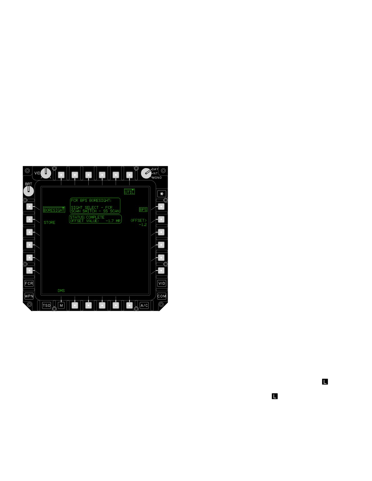
4.46.1 BPS BORESIGHT Page Description. The BPS
blade position indicator angle (offset value) can be then
page (fig 4-62) provides the maintenance pilot with a
provided to the WP, once the crewmember decides to ac-
means of boresighting the rotor system with the FCR scan
cept the new value. The intended effect is to maximize the
beam. It also provides the operating crew a means to
overall FCR performance by synchronizing rotor blade
verify the displayed BPS OFFSET value.
position with FCR emission and reception.
4.46.4 Conditions For Use. The BPS boresight can
only be performed if certain specified dynamic air data
conditions and aircraft sensor conditions are met. These
conditions are:
a. The FCR is powered ON and operational with BIT
complete.
b. The aircraft is between 200 and 300 ft AGL.
c. The aircraft velocities are less than 5 km/hr in all
axes.
d. The blade tracker is locked.
e. The radar altimeter is operational and producing
valid data.
4.46.5 OFFSET Button. The BPS OFFSET button dis-
LBA2595
plays the currently stored (last stored) blade position off-
set value. Depressing the button provides the crewmem-
ber with the capability to manually edit the currently stored
Figure
4-62.
BPS Page
blade position sensor value via the KU.
4.47 SIGHT SELECTION
The BPS page contains the following unique buttons:
The right handgrip (RHG) or collective mission grip sight
• T6
UTIL button
select switch is a momentary contact switch used to select
the helmet mounted display (HMD), TADS, or FCR
as
• L2
STORE button
the active LOS for weapons processing. The sight select
• R1
BPS button
switch also incorporates a LINK
function. Sight select
functions are as follows:
• R2
OFFSET button
4.46.2 STORE Button. The BPS STORE button is dis-
4.47.1 Sight Select HMD. When HMD is the selected
played only when the BPS has provided a valid scan feed-
sight, HMD is the active line of sight for weapons proces-
back. It allows the crewmember to automatically store the
sing. Selecting any other sight will deselect the HMD.
Use or disclosure of this information is subject to the restriction(s) on the title page of this document.
4-60
TM 1-1520-251-10
4.47.2 Sight Select TADS. When TADS is the selected
c. f the CPG selected sight is FCR and LINK is se-
sight in the CPG station, TADS is the active line of sight for
lected, selecting the RHG SLAVE switch allows the CPG
weapons processing. Selecting FCR will deselect TADS
to manually offset the TADS LOS from the NTS. This can
and the TADS will be commanded to FXD unless FCR
be used to view the area surrounding the NTS or to keep
was linked to TADS. In this case, the TADS LOS will re-
the target centered when going to narrower Fields of View
main at its current position. The TADS position of this
on the TADS. Re-selecting the RHG SLAVE switch forces
switch is not active in the pilot station.
the TADS back to the NTS position.
d. The link function is ignored when the selected sight
is helmet mounted display (HMD) or when both TADS and
4.47.3 Sight Select FCR
When FCR is the selected
FCR are sight and acquisition selects.
sight, FCR (NTS) in that crew station is the active line of
sight for weapons processing. This selection also calls up
e. The link function is set to off when a sight or ac-
the FCR page targeting format for the selected mode on
quisition selection is made that does not comply with the
the left MPD (if not already displayed). Selecting TADS
conditions mentioned above.
will deselect FCR and the FCR will be commanded to FXD
unless TADS was linked to FCR. In this case the FCR
f. Either crewmember has the ability to LINK the FCR
(centerline) will remain at its current position. Selection of
or TADS away from the other crewmember. For example,
the FCR from either crew station is based on a last-to-se-
if the CPG’s selected sight is TADS and the pilot selects
lect logic. If accepting an RFHO while sight select is FCR,
LINK, the CPG’s sight will automatically change to HMD.
then targeting data will be provided from the IDM data and
If the CPG then reselects TADS, the pilot’s link function
not ownship radar.
will be set to off.
g. If the pilot selected sight is FCR and LINK is se-
lected, the TADS FOV will automatically change to wide if
4.47.4 Sight LINK Function
The link function is
DVO (ORT only) or DTV is the selected sensor, or me-
used to set the FCR centerline to the TADS LOS when the
dium if FLIR is the selected sensor. Subsequently, sensor
selected sight is TADS or to set the TADS LOS to the FCR
and FOV selections can be made by the CPG.
NTS LOS when the selected sight is FCR in the CPG sta-
4.48 ACQUISITION SOURCE SELECTION
tion. In the pilot station, it is used only to set the TADS
LOS to the FCR NTS LOS. Placing the switch momentari-
An acquisition source is selected by the pilot or CPG, us-
ly down to the LINK position will toggle the LINK mode al-
ing the WPN page, the FCR page
, or TSD page ACQ
ternately between ON and OFF in either crew station. The
button. This selection is independent in each crew station.
link function operates as described below:
When an acquisition source is selected, the selected sight
can be slaved or provide cueing to the acquisition source
LOS/coordinate point. After a sight and an acquisition
a. If TADS is the selected sight and LINK is selected,
source are selected, slaving and/or cueing in the CPG sta-
the FCR azimuth scan centerline is aligned to the TADS
tion is selected by pressing the RHG SLAVE switch. Se-
LOS. If a single or continuous scanburst is selected, the
lecting a different acquisition source or pressing the RHG
FCR scan centerline will not follow TADS movement until
SLAVE switch again in the CPG station deselects slave.
the scan is complete. A continuous scanburst must be de-
In the pilot station, slaving and/or cueing is in effect on
selected before the scan centerline is realigned to the
selection of an acquisition source. If an invalid acquisition
TADS LOS.
LOS condition is created, the acquisition source is de-
faulted to FXD. Acquisition options are not displayed
when that acquisition source is not available (not powered
or failed). In addition, an acquisition option will not be dis-
b. If the FCR is the selected sight and LINK is se-
played when the option is not valid based on the selected
lected, the TADS LOS is aligned to the FCR next-to-shoot
sight.
(NTS) target at the completion of a single scanburst or at
the completion of each scanburst within a scanburst. Dur-
4.48.1 Available Acquisition Sources.
ing continuous scanburst, the TADS LOS is set to the FCR
NTS target at the completion of a scanburst. When the RF
a. Pilot Acquisition Sources. The pilot receives
missile seeker is in a track state, the TADS LOS is aligned
cueing data upon selection of an acquisition source when
to the seeker LOS. When no NTS is detected, the LINK
the sight selected is HMD. The slaving of the FCR is pro-
selection is ignored.
vided when the FCR is the selected sight. Cueing can be
Use or disclosure of this information is subject to the restriction(s) on the title page of this document.
Change 3
4-61

TM 1-1520-251-10
turned off in pilot’s crewstation via the WPN UTIL page.
SLAVE switch to on. The CPG may use as an acquisition
Slaving of the FCR can not be turned off. The pilot may
source:
use as an acquisition source:
• PHS - Pilot’s HMD LOS.
• PHS - Own HMD (available only when the sight is
• GHS - Own HMD (when it is not the selected sight).
FCR.)
• SKR - Tracking missile seeker.
• GHS - CPG helmet sight.
(1) Hellfire laser seeker is tracking laser energy ei
• SKR - Tracking missile seeker
ther ownship or remote designator.
(1) Hellfire laser seeker is tracking laser energy ei
(2) RF Hellfire is tracking a next-to-shoot target.
ther ownship or remote designator.
• RFI - Highest priority RFI detected emitter azi-
(2) RF Hellfire is tracking a next-to-shoot target.
muth.
• FCR - The next-to-shoot target LOS (when the
• RFI - Highest priority RFI detected emitter azi-
sight is either TADS or HMD).
muth.
• FXD - Fixed forward (centerline of the aircraft with
• FCR - The next-to-shoot target LOS.
an elevation relative to the airframe of negative
• FXD - Fixed forward (centerline of the aircraft with
4.9°).
an elevation relative to the airframe of negative
• TADS (when it is not the selected sight).
4.9°).
• W01, C51, T01 - One of the stored waypoints,
• TADS.
hazards, control measures, or target/threat points.
• W01, C51, T01 - One of the stored waypoints
Both the pilot and CPG have the added feature of being
hazards, control measures, or target/threat points.
able to LINK the TADS to the FCR LOS via a single action.
b. CPG Acquisition Sources. The CPG is required
This feature allows the visual confirmation of targets,
to manually “slave” the selected sight to the acquisition
helping in the reduction of potential fratricide.
LOS via the RHG Slave control. The CPG has the added
capability, via a single action, to LINK the FCR to the
4.48.2 Sight Selection Acquisition Source. The fol-
TADS LOS in order to obtain more detail on the acquired
lowing matrix (table 4-20) provides an indication of what
target. If the CPG selects (changes) an acquisition
cueing and/or slaving is provided for each crewmember
source, the slave function is automatically set to off. Slav-
based on the selected sight and the selected acquisition
ing and/or cueing will be in effect upon actuating the
source.
Table 4-20. Sight Selection/Crewstation/Acquisition Source Matrix
Selected
Crewstation
Acquisition
Slaving
Cueing
Not Valid/
Notes
Sight
Source
Provided
Provided
Not Available
TADS
PLT
PHS
X
GHS
X
SKR
X
RFI
X
FCR
X
FXD
X
TADS
X
Txx
X
TRN
X
Use or disclosure of this information is subject to the restriction(s) on the title page of this document.
4-62
Change 3

TM 1-1520-251-10
Table 4-20. Sight Selection/Crewstation/Acquisition Source Matrix (cont)
Selected
Crewstation
Acquisition
Slaving
Cueing
Not Valid/
Notes
Sight
Source
Provided
Provided
Not Available
TADS
CPG
PHS
X
X
1,2
GHS
X
X
1,2
SKR
X
X
1,2,7
RFI
X
X
1,2,8
FCR
X
X
1,2,9
FXD
X
X
1,2
TADS
X
12
Txx
X
X
12
TRN
X
X
1,2
FCR
PLT
PHS
X
5
GHS
X
SKR
X
7
RFI
X
6,8
FCR
X
10
FXD
X
TADS
X
13
Txx
X
TRN
X
FCR
CPG
PHS
X
4
GHS
X
4
SKR
X
4,7
RFI
X
14
FCR
X
10
FXD
X
11
TADS
X
4,13
Txx
X
4
TRN
X
4
HMD
PLT
PHS
X
GHS
X
6
SKR
X
6,7
RFI
X
6,8
FCR
X
6,9
FXD
X
6
TADS
X
6
Txx
X
6
TRN
X
6
Use or disclosure of this information is subject to the restriction(s) on the title page of this document.
Change 2
4-63

TM 1-1520-251-10
Table 4-20. Sight Selection/Crewstation/Acquisition Source Matrix (cont)
Selected
Crewstation
Acquisition
Slaving
Cueing
Not Valid/
Notes
Sight
Source
Provided
Provided
Not Available
HMD
CPG
PHS
X
1,3
GHS
X
SKR
X
1,3,7
RFI
X
1,3,8
FCR
X
1,3,9
FXD
X
1,3
TADS
X
1,3
Txx
X
1,3
TRN
X
1,3
NOTE: TADS is not available for sight selection if either crewmember is using it as a sensor (i.e. NVS MODE switch in
NORM or FXD). Pilot can not sight select TADS.
NOTES:
1.
When the RHG SLAVE switch is actuated to slaved, cueing dots and the cued LOS reticle will be dis-
played on the ORT or TEDAC displays and the HMD to provide cueing to the selected acquisition LOS.
2.
When the RHG SLAVE switch is actuated to not slaved, the TADS LOS is controlled by the manual
tracker and no cueing is displayed.
3.
When the RHG SLAVE switch is actuated to not slaved, no cueing is displayed.
4.
When the RHG SLAVE switch is actuated to slaved, the FCR centerline will be set to the selected ac-
quisition LOS. When the SLAVE switch is actuated to not slaved, the FCR centerline is controlled by
the manual tracker and/or the arrow buttons on the FCR page.
5.
When selected, the FCR centerline will be set to the PHS LOS unless the pilot has manually moved the
centerline using the MPD arrow buttons on the FCR page.
6.
When selected, cueing dots and the cued LOS reticle will be displayed on the HMD providing cueing
to the selected acquisition LOS.
7.
The tracking priority missile seeker LOS will be the selected acquisition LOS with the tracking priority
missile seeker defined as follows: SAL - tracking the priority laser channel, RF - tracking the NTS tar-
get, or ATA - uncaged and tracking.
8.
The #1 RFI or selected RFI emitter is the selected acquisition LOS, with slaving and/or cueing provided
to the azimuth of the RFI emitter and 0° elevation (local horizontal).
9.
The FCR NTS is the selected acquisition LOS. If no valid NTS target exists, the slaving and/or cueing
is not provided. The data used for the FCR NTS LOS can be derived from autonomous FCR target
data or from FCR target data received via the IDM.
10.
If FCR is the selected sight or if the FCR is linked to the TADS LOS.When the ORT SLAVE switch is
actuated to slaved, the FCR centerline will be set to the FXD forward position.
11.
When the RHG SLAVE switch is actuated to not slaved, the FCR centerline will be controlled by the
manual tracker and the FCR centerline will be commanded to the start scan position (offset to the left)
to reduce the time to start scan.
12.
If TADS is the selected sight or the TADS is linked to the FCR NTS LOS.
13.
Not available if TADS is linked to the FCR NTS LOS.
14.
Cued search is used to rapidly scan RFI detected targets with the FCR.
Use or disclosure of this information is subject to the restriction(s) on the title page of this document.
4-64
Change 3
TM 1-1520-251-10
4.49 RANGE AND RANGE SOURCE SELECTION
b. Automatic Range. Entering A on the KU selects
automatic range for the weapons processor. The weap-
The weapons processor uses the last range obtained (laser,
ons processor calculates range of the selected sight LOS
FCR
, coordinate point, manual, or automatic). The range
at intercept with the target, which is assumed to be at zero
will be used by the weapons processor until another valid
radar altitude. The display range is 0.1 to 50.0 in km and
range source is selected or data from the current range
tenths of km increments (AXX.X).
source becomes invalid. A default range is used when no
4.49.5 Default Range. A default range is used when no
range is in memory or when range cannot be computed from
range is in memory at power-up, or when range cannot be
the existing source. An automatic or manual range source
computed from the existing source. Default range for the
can be selected from the weapon page; however, a manual
CPG is 3.0 km. Default range for the pilot is 1.5 km. The
range cannot be entered when FCR is the selected sight.
weapons processor will use the default range until a valid
Range and range source is displayed in the HAD on the
range source is used or until a valid range can be calcu-
IHADSS flight and weapons symbology formats as well as
lated from the original range source.
the FCR page
4.49.6 HMD - Gun Default Range. If the aircraft is
4.49.1 Laser Range. When the CPG fires the laser us-
equipped with MTADS provisions, range will default to
ing the RHG laser trigger, laser becomes the range
manual range when HMD is the selected sight and the
source. Squeezing the laser trigger switch to the first det-
gun system is actioned. If the manual range is zero, the
ent fires 3 burst of laser energy in 1 second for target
default range for that crew station will be used.
ranging. Squeezing the laser trigger to the second detent
4.50 SIGHT SUBSYSTEM - DEGRADED MODES OF
fires a continuous burst of laser energy for target designa-
OPERATION
tion and continuous range updates. The display range is
500 to 9999 in 1m increments (XXXX).
4.50.1 TEU Fail. If the TEU fails, PNVS is commanded
to direct mode by the weapons processor. When PNVS is
4.49.2 Radar Range
. When FCR transmit is activated
in direct mode, PNVS turret movement is controlled by
using the collective mission grip or LHG scan select
IHADSS and the PNVS electronic unit (PEU). In PNVS di-
switch, radar becomes the range source. Radar range is
rect, azimuth coverage is limited to ± 75° with degraded
entered when the pilot or CPG activates the FCR scan se-
LOS accuracy. PNVS turret movement may become errat-
lect switch. The weapons processor uses the NTS target
ic beyond ± 75°.
range as pilot or CPG range as appropriate. If the aircraft
4.50.2 IHADSS Fail. If IHADSS video or position control
is equipped with MTADS provisions, and a manual range
commands fail, the pilot/CPG NVS MODE switch should
has been entered, radar range may be reestablished by
be set to FIXED. The PNVS turret is commanded to fixed
selecting a NTS target or conducting a new scan. The dis-
forward and the PNVS image is displayed on an MPD
play range is 0.0 to 9.9 in km and tenths of km increments
without azimuth or elevation correction.
(RXX.X).
4.50.3 IHADSS Single DP Operation. During single DP
4.49.3 Target Range. Target range is the navigation
operation both crewstations share common symbology
range from the helicopter present position to a coordinate
and imagery on their HMDs. Symbology brightness is
point. Target range is entered automatically when a coor-
controlled by the crewmember whose symbology and
dinate point (TXX, WXX, CXX or [
BLK 2
TRN] ) is se-
imagery is presented on both HMDs. Control of the HMD
lected as the acquisition source and the RHG SLAVE is
presentation is as follows: If the NVS MODE switch is OFF
pressed to select slave. If the aircraft is equipped with
in both crewstations the pilot’s symbology and imagery
MTADS provisions, and a manual range has been en-
will be presented on both HMDs. If only one crewmem-
tered, target range may be reestablished by again select-
ber’s NVS MODE switch is NORM or FIXED, that crew-
ing the coordinate point as the acquisition source. The dis-
member’s symbology and imagery will be presented on
play range is 0.1 to 32.0 in tenths of km increments
both HMDs. If both crewmembers’ NVS MODE switches
(NXX.X).
are NORM or FIXED, the symbology and imagery of pilot
4.49.4 Manual Range Entry. Selecting the WPN page
will be displayed. Subsequent selection of the NVS switch
MANRNG button and entering a numeric range (manual)
will select the crewmember’s symbology and imagery.
or entering an alphabetic letter A (automatic) on the KU
The HMD FORMAT OWNER CUE (Figure 4-27) will be
initially selects a range source for the weapons processor.
displayed with the appropriate format while operating in
a. Manual Range. Entering a numeric range for se-
single DP. The HMD FORMAT OWNER CUE will flash for
lected sight ranging on the KU selects an initial range for
three seconds and then remain displayed in a solid mes-
the weapons processor to use. The range entry is from
sage layout when the format ownership is changed and
100m to 50,000m in 1m increments. The display range is
DP operation changes from normal to single. The HMD
0.1 to 50.0 in km and tenths of km increments (MXX.X).
FORMAT OWNER CUE will flash for three seconds when
Use or disclosure of this information is subject to the restriction(s) on the title page of this document.
Change 4
4-65
TM 1-1520-251-10
DP operations changes from single to normal operation
SHUTDOWN HOT message will be displayed on the DMS
and then extinguish. In single DP operation the crewmem-
page.
ber viewing the opposite format is inhibited from firing the
4.50.6 FCR Useable Range
FCR usable range can
weapon systems.
be reduced by transmitter, receiver, or LPRF failures. Re-
MPD VIDEO Page presentation of PILOT HMD or CPG
ceiver and LPRF failures usually result in an FCR not op-
HMD underlay selections will continue to display dual DP
erational fault. One of the messages described below will
format and imagery. Therefore, the MPD may display a
be displayed only on the DMS page. The transmitter is the
video and format that does not match the HMD display.
highest failure rate item. The transmitter failure rate is
This may be used to the crewmenbers advantage, as it
dominated by 4 identical multipliers. The multiplier outputs
enables the crewmember to observe the video/format of
are summed together to produce the desired transmitter
their sensor on the MPD during single DP operation.
power output. Each multiplier has a BIT monitor. If one
multiplier is bad, an FCR RANGE 10% DEGR message is
4.50.4 PNVS Fail. In the event of a PNVS failure, TADS
displayed. If 2 multipliers are bad, an FCR RANGE 20%
FLIR can be switched to pilot control as emergency back-
DEGR message is displayed. If three multipliers are bad,
up. The pilot sets the collective flight control grip night vi-
an FCR RANGE 35% DEGR message is displayed. If all
sion select switch to TADS. The TADS assembly is slaved
4 multipliers are bad, the FCR is not operational.
to the pilot helmet LOS and FOV is set to WFOV. The slew
4.50.7 RFI Only Operational with FCR Not Operation-
rate of the TADS turret assembly is slower than the PNVS
al
If the radar fails, the FCR can be configured for
turret assembly.
RFI only mode operation. To configure the FCR for RFI
4.50.4A Video Fail Conditions
only operation, the MMA is mechanically pinned to fixed
forward and the RFI processor is connected to multiplex
a. Frozen Video Frozen video occurs due to loss of
bus 3A/B (TM 1-1520-251-CD). When aircraft power is
video link communications. The result of this failure will be
applied, the MMA mode is set to PINNED on the WPN or
frozen video and a VIDEO FROZEN status message. Vid-
FCR UTIL page, which subsequently allows selection of
eo will be removed if it remains frozen for more than four
the RFI ON/OFF button. With RFI selected ON, RFI de-
seconds.
tected emitters will be displayed on the ASE page and
b. Degraded Video Degraded video occurs when
TSD page.The flight crew can select BIT ORIDE anytime
errors are detected in the video signal. The result of this
during the BIT sequence. When FCR BIT ORIDE is se-
condition may be degradation of all or a portion of the vid-
lected from the FCR utility page, Initiated BIT (IBIT) will
eo image and a VIDEO DEGR status message. Video will
only conduct critical item BIT and will terminate early (after
not be removed in this condition.
a minimum run time of approximately 25 - 45 seconds),
c. Loss of Bus Communications In the event bus
and the FCR will go directly to the selected mode of op-
communications is lost, the turret (TADS or PNVS) will
eration. Continuous BIT will still provide notification of
move to fixed forward in five seconds. Video will switch to
FCR functional status but will not detect faults that require
FLIR if DTV or DVO is selected and the sensor will switch
intrusive testing. It is recommended that IBIT is selected
to run the entire BIT when the situation permits.
to WFOV if not currently selected.
4.50.8 FCR BIT Override
The flight crew can select
4.50.5
FCR Overtemperature
The FCR MMA,
BIT ORIDE anytime during the BIT sequence. When FCR
LPRF, and PSP contain temperature sensors which are
BIT ORIDE is selected from the FCR utility page, Initiated
located near heat producing or heat sensitive compo-
BIT (IBIT) will only conduct critical item BIT and will termi-
nents. When any temperature sensor detects 80 - 90% of
nate early (after a minimum run time of approximately 25
an overheat threshold, an FCR HOT message is dis-
- 45 seconds), and the FCR will go directly to the selected
played on the HAD and the DMS page. If the FCR is al-
mode of operation. Continuous BIT will still provide notifi-
lowed to operate until the maximum temperature thresh-
cation of FCR functional status but will not detect faults
old is reached, the FCR will automatically shut down. The
that require intrusive testing. It is recommended that IBIT
FCR overtemperature shutdown can be inhibited by se-
is selected to run the entire BIT when the situation per-
lecting the FCR utility page FCR TEMP ORIDE button af-
mits.
ter receiving the FCR HOT message prior to reaching the
maximum temperature threshold. With the automatic
4.50.9
Degraded FCR Modes
Partial failure of
shutdown inhibited, the FCR will continue to operate (with
ATM, GTM, or TPM functions, directed by BIT, will cause
possible degraded system performance) until permanent
FCR MTI DEGR, FCR STI DEGR, FCR STI FAIL, or FCR
damage occurs. If the FCR detects a maximum tempera-
TPM DEGR messages to be displayed on the DMS page.
ture threshold without override command, the FCR will be
The FCR will continue to operate without all of the operat-
powered down by the weapons processor and an FCR
ing mode features available for use.
Use or disclosure of this information is subject to the restriction(s) on the title page of this document.
4-66
Change 4

TM 1-1520-251-10
4.50.10 Degraded FCR Azimuth Servo
. Faults de-
message displayed while the FCR remains in operation indi-
tected in azimuth rate sensing circuits can cause a FCR AZ
cates that maintenance should be performed as soon as pos-
SERVO DEGR message to be displayed on the DMS page.
sible.
The effects of the degraded azimuth servo condition can be
reduced by minimizing yaw motion of the aircraft during scan-
ning. This degraded condition could occur at the same time
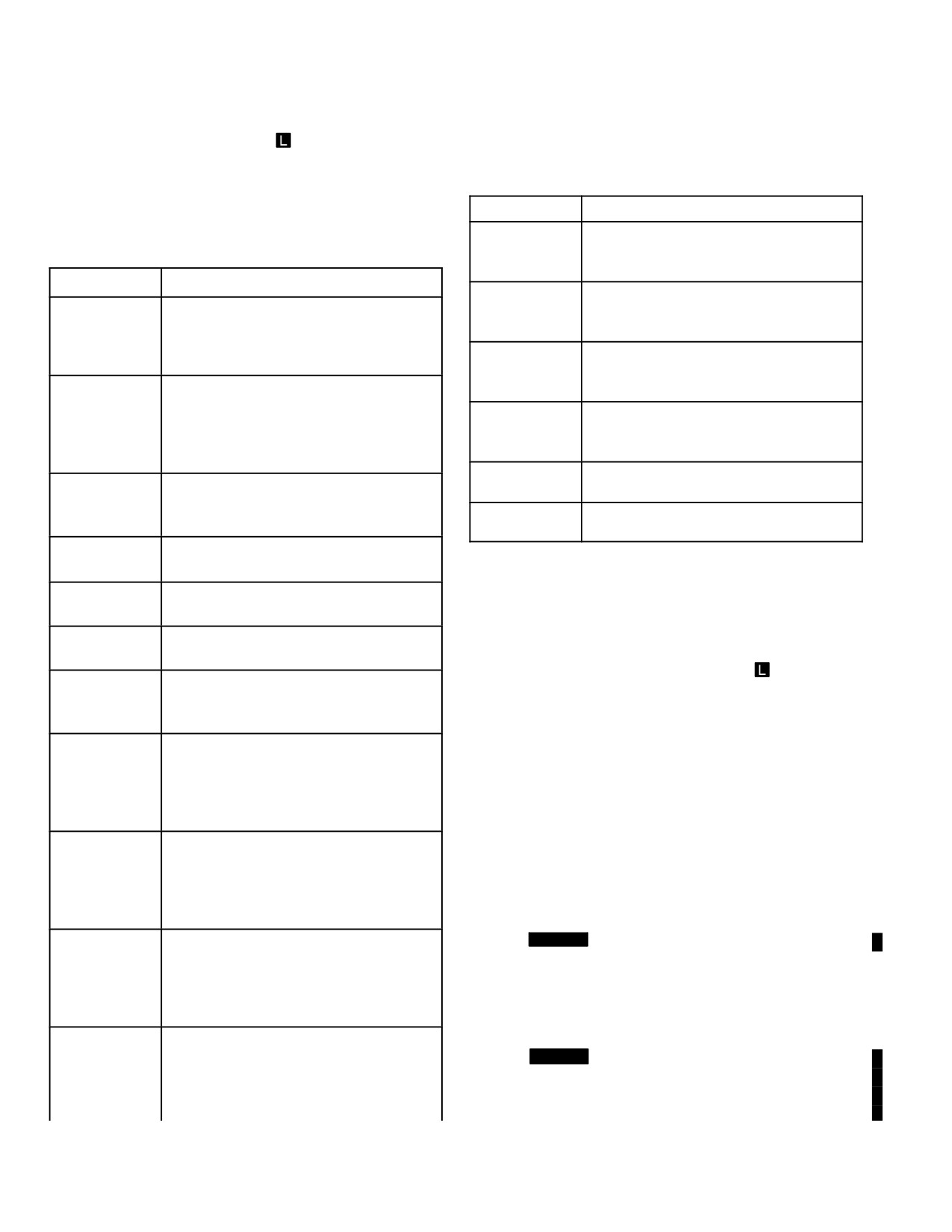
Table 4-21. DMS Page FCR Functional Loss
as a degraded elevation servo (para 4.50.11). If degraded
Messages
azimuth and elevation servo indications occur at the same
time, minimize yaw, pitch, and roll motion of the aircraft during
scanning. If the azimuth servo is detected as not operational,
a FCR FAIL message will be displayed.
Message
Description
4.50.11 Degraded FCR Elevation Servo
. Faults de-
FCR AZ SER-
Indicates that the FCR azimuth scan
tected in elevation rate sensing circuits can cause a FCR EL
VO DEGR
capability is degraded. Refer to para-
SCAN DEGR message to be displayed on the DMS page.
graph 4.50.10 for corrective action.
The effects of the degraded elevation servo condition can be
FCR BIT LOG
Indicates that the FCR has lost the
reduced by minimizing pitch and roll motion of the aircraft
INOP
ability to store BIT data. FCR mission
during scanning. This degraded condition could occur at the
capabilities are still fully functional.
same time as a degraded azimuth servo (para 4.50.10). If
FCR BIT LOG
Indicates that the FCR has reached a
degraded azimuth and elevation servo indications occur at
LIMIT
BIT data storage limit. FCR mission
the same time, minimize yaw, pitch, and roll motion of the air-
capabilities are still fully functional.
craft during scanning. If the elevation servo is detected as not
FCR BPI
Indicates that the FCR has detected a
operational, a FCR FAIL message will be displayed.
DEGR
BPI failure. FCR target information
may be unreliable.
4.50.12 FCR to Missile Target Assignment Status
FCR CALS
Indicates that the FCR can not recali-
. Faults detected in FCR hardware that could cause azi-
DEGR
brate. System accuracy will degrade
muth or elevation pointing errors during RF missile target as-
over time.
signments will cause a FCR HANDOVER DEGR message to
be displayed on the DMS page. This fault could direct the
FCR CAL
Indicates that the FCR may be
JAMMED
jammed during calibration (para
missile (LOBL recommended for this fault condition) to a LOS
4.50.13).
that will not allow the missile to acquire the target or will direct
the missile to acquire the wrong target. The TADS/PNVS
FCR FDI
Indicates that FCR fault detection/
DEGR
isolation capability has been de-
LOS should be aligned to the FCR NTS or the tracking seek-
graded.
er LOS for desired target verification.
FCR EL
Indicates that the FCR elevation scan
4.50.13 Potential Jamming of FCR Calibrations
. The
SCAN DEGR
capability is degraded. Refer to para-
effects of a potential jammer on FCR calibrations cause a
graph 4.50.11 for corrective action.
FCR CAL JAMMED message to be displayed on the DMS
FCR FAIL
Indicates that the FCR has been shut-
page. The effect of a potential jammer on calibrations can be
down as non-operational. RFI only op-
reduced by changing the start position of a sector scan. Dur-
eration may be possible (para 4.50.7).
ing a circular scan, reposition the aircraft in yaw.
Message will be cleared if power is ap-
plied to the FCR.
4.50.14 RFI Degraded
. Degraded RFI operation is indi-
FCR HAND-
Indicates that FCR to missile target
cated by an RFI DEGR message displayed on the DMS
OVER DEGR
assignment is degraded (para
page. When this message is displayed, RFI information may
4.50.12).
be unreliable.
FCR HOT
Indicates that FCR has detected
4.50.15 FCR Functional Loss Messages
. The follow-
80 - 90% of an overtemperature thresh-
ing DMS page fault messages indicate that the FCR/RFI has
old (para 4.50.5).
lost some or all operational capability. There may not be a
FCR INOP
Indicates that FCR nonvolatile has
HAD message related to functional losses that degrade op-
ZEROIZED
been zeroized. The FCR is not opera-
eration without complete loss of operation. Table 4-21 list the
tional. The FCR PSP nonvolatile
DMS page FCR functional loss messages, description, and
memory ECA must be removed and
corrective action (if any) for possible continued operation. Any
reprogrammed or replaced.
Use or disclosure of this information is subject to the restriction(s) on the title page of this document.
Change 4
4-67
TM 1-1520-251-10
Table 4-21. DMS Page FCR Functional Loss
Table 4-21. DMS Page FCR Functional Loss
Messages
Messages
Message
Description
FCR VIDEO
Indicates that FCR RMAP/TPM radar
DEGR
video generation capability is de-
graded.
Message
Description
FCR VID
Indicates that FCR RMAP radar video
FCR MMA
Indicates that the FCR MMA cooling
ZOOM DEGR
may be degraded in display zoom op-
COOL DEGR
fan is not operational. An overtemper-
eration.
ature condition could be the result
FCR VOLT-
Indicates that an FCR power supply
(para 4.50.5).
AGE DEGR
voltage is out of tolerance. FCR in-
FCR
Indicates that MTI is degraded. Mov-
formation may be unreliable.
MTI DEGR
ing targets may not be detected or
RFI BPI
Indicates that the RFI has detected a
may be shown with the wrong classifi-
DEGR
BPI failure. RFI information may be
cation. FCR operation in other modes
unreliable.
may still be possible (para 4.50.9).
RFI DEGR
Indicates that RFI information may be
FCR RADAR
Indicates that any FCR data could be
unreliable (para 4.50.14).
DEGR
invalid (symbol position in azimuth or
RFI FAIL
Indicates that the RFI is not operation-
elevation, classification, etc.
al.
FCR RANGE
Indicates that FCR range is 90% of full
10% DEGR
capability (para 4.50.6).
4.51 VIDEO SUBSYSTEM
FCR RANGE
Indicates that FCR range is 80% of full
20% DEGR
capability (para 4.50.6).
The Video Subsystem provides real time composite video
for the MPDs VIDEO page and VCR. Composite video is
FCR RANGE
Indicates that FCR range is 65% of full
composed of TADS FLIR, TADS DTV, PNVS FLIR with
35% DEGR
capability (para 4.50.6).
Flight/Weapon format symbology, or FCR
imagery with
FCR
Indicates that the FCR has lost the
symbology. The MPDs can display real-time sensor video
RESTART
ability to initiate a warm start se-
underneath all other MPD format symbology. Each crew
DEGR
quence.
station can select the VIDEO page for independent dis-
FCR
Indicates that the FCR has been shut-
play on either of their MPDs. Either crewmember can ac-
SHUTDOWN
down as a result of a detected over-
cess the video recorder controls to select what is to be re-
HOT
temperature condition. Message will
corded, to start and stop recording, and to play recorded
be cleared if power is applied to the
video. Sensor information does not have to be displayed
FCR.
to be recorded.
FCR STI
Indicates that STI is degraded. Sta-
DEGR
tionary targets may not be detected or
Only one sensor can be recorded at a time. Once se-
classified. FCR operation in other
lected, the video recorder will record the selected system
modes may still be possible (para
in the format it would be presented to the crewmember.
4.50.9).
FCR STI FAIL
Indicates that STI has failed. Station-
4.51.1 [
BLK 1
Video Recorder. The video record-
ary targets may not be detected or
er records 875 line video, and is located in the right aft
classified. FCR operation in other
avionics bay. The recorder controls are available to both
modes may still be possible (para
crewmembers through the VCR page. Tape length control
4.50.9).
is also available through the LMP.]
FCR TPM
Indicates that TPM is degraded. Ob-
DEGR
stacle symbol or profile line elevation
4.51.2 [
BLK 2
Video Recorder. The video recorder
position may be wrong. FCR operation
records 525 line video, and is located in the right aft avion-
in other modes may still be possible
ics bay. The recorder controls are available to both crew-
(para 4.50.9).
members through the VCR page.]
Use or disclosure of this information is subject to the restriction(s) on the title page of this document.
4-68
Change 2
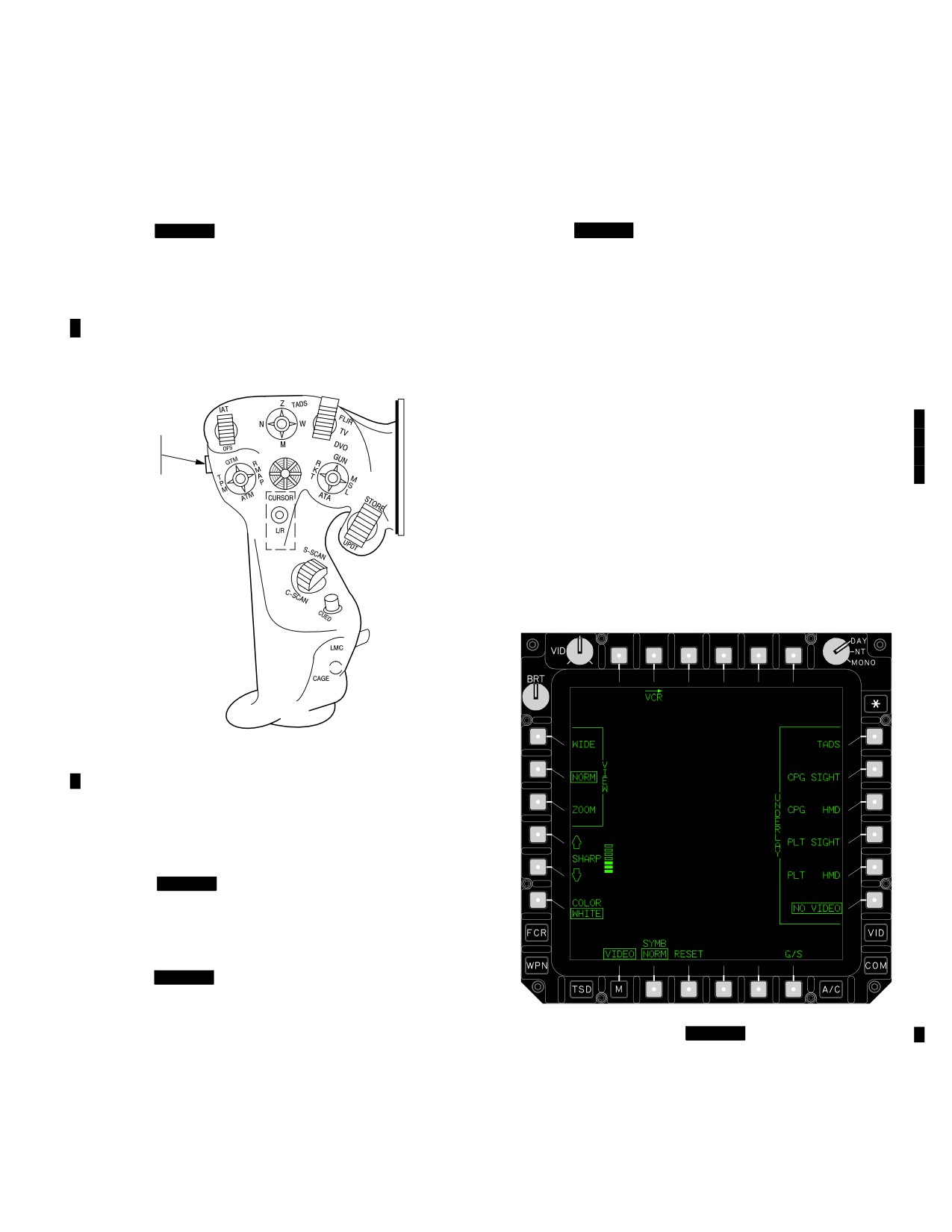
TM 1-1520-251-10
4.52 CONTROLS AND DISPLAYS
controlled with the VCR rotary knob on the COMM panel.
If any radio is operating in a secure mode, no audio is re-
Controls and displays are integrated into the following ma-
corded. Monitored radio and other headset audio for the
jor Video Subsystem components:
crewmember that selected VCR recording is recorded at a
constant volume.]
• Video recorder controls
• [
BLK 1
Load Maintenance Panel controls]
4.52.5
[
BLK 2
Communications (COMM) Panel
Controls. Audio playback volume within each headset
• Communications Panel controls
can be independently controlled with the VCR rotary knob
• Multipurpose displays (MPDs)
on the COMM panel. If any radio is operating in a secure
mode, no audio is recorded. Monitored radio and other
4.52.1 Left Hand Grip. The LHG Video Record push-
headset audio for the crewmember that selected VCR re-
button (fig 4-63) toggles the VCR between its default
cording is recorded at a constant volume.]
mode (STOP or STANDBY), and RECORD modes.
4.53 VIDEO PAGE
The VIDEO page (fig 4-64A) is used to select VCR for
real-time video display, select IMAGE for still pictures, se-
VIDEO
RECORD
lect G/S for display optimization, and mode operation for
BUTTON
the VIDEO page in that crew station. If the VIDEO page
underlay buttons are set to NO VIDEO, and the pilot se-
lects the VIDEO page, the pilot’s HMD underlay will be se-
lected by default. This gives the pilot the ability to quickly
access his active NVS underlay (PNVS or TADS) in the
event of HMD failure. If there is no real-time video pres-
ented on an MPD, and the CPG selects the VIDEO page,
the CPG’s sight video underlay will be selected by default.
LBA2040
Figure 4-63. Left Hand Grip Control
4.52.2 Video Recorder Controls. Recorder controls
are provided through the crew station VCR page.
4.52.3
[
BLK 1
Load Maintenance Panel Con-
trols.
The Load Maintenance Panel can be used by the
ground personnel to indicate what tape length has been
loaded.]
4.52.4
[
BLK 1
Communications (COMM) Panel
Controls. The VCR provides a short tone when the
crew commands an event mark. This tone and audio play-
back volume within each headset can be independently
Figure 4-64.
[
BLK 1
VIDEO Page]
Use or disclosure of this information is subject to the restriction(s) on the title page of this document.
Change 3
4-69
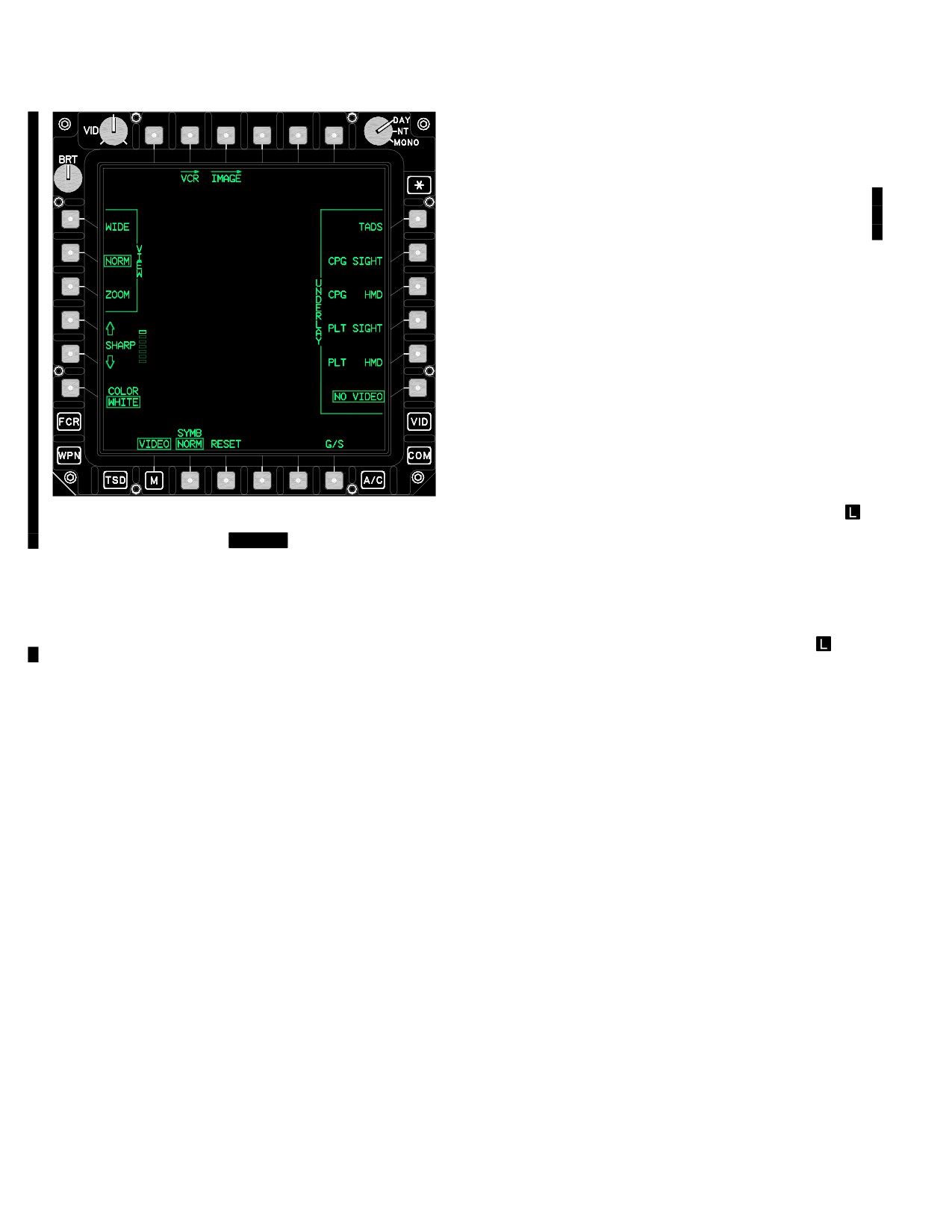
TM 1-1520-251-10
4.53.1 VCR Button. The VCR button is provided on the
VIDEO page. Selection of the VCR button from the VIDEO
page calls the VCR page.
4.53.1A IMAGE Button. The IMAGE button is provided
on the VIDEO page. Selection of the IMAGE button from
the VIDEO page calls the IMAGE page.
4.53.2 Declutter Button. Selection of the VIDEO page
Video Select button initiates decluttered mode operation
on the VIDEO page for that crew station.
The button label changes to indicate the video symbolgoy
to be selected for presentation. The label is either C - FLT,
P-FLT, TADS, C-FCR, or P-FCR. Pilot or CPG owner-
ship is indicated by the initial P - or C - . TADS is always
owned by the CPG, and presents weapons symbology.
FLT indicates flight symbology, and FCR indicates FCR
targeting symbology. During decluttered mode operation,
the display is cleared of all button labels other than the
boxed VIDEO VSEL button, and abbreviated versions of
VIEW (W, N, Z) and the SHARP buttons presenting video
imagery and associated Flight, Weapon, or FCR
symbology. Although the menu button label is not shown
Figure 4-64A.
[
BLK 2
VIDEO Page]
when VSEL is selected, the menu button continues to
function normally. The default VIDEO page presentation is
with this button selected.
The following buttons can be found on the VIDEO page:
• T2
VCR button
4.53.3
VIEW Buttons. The VIEW buttons provide
selection of the video view modes for all non - FCR
vid-
• T3
IMAGE button
eo underlay beneath the MPD formats. When FCR sym-
• T6
Video Symbology Select button
bols are not presented, the VIEW buttons also affect FCR
(C-FLT, P-FLT, TADS, C-FCR, or
video. The default VIEW mode is NORM, in which the
P-FCR)
center 75% of the video image is presented. The WIDE
VIEW presents the center 95% of the image, with black
• L1
VIEW WIDE Button
bars filling blank video area on the top and bottom of the
• L2
VIEW NORMal button
underlay. The ZOOM VIEW presents a 2:1 electronic
• L3
VIEW ZOOM button
zoom of the WIDE image. The VIEW buttons are abbrevi-
ated to W, N, and Z and their surrounding bracket is re-
• L4
SHARP scroll up button
moved when VIDEO VSEL is selected.
• L5
SHARP scroll down button
4.53.4 SHARP Buttons. The SHARP buttons allow the
• L6
COLOR WHITE/GREEN button
crew to amplify presentation of fine detail information. The
• R1
UNDERLAY TADS button
optimal SHARP setting may vary with changing sensors
• R2
UNDERLAY CPG SIGHT button
or scene content. Applying SHARP to video containing
noise may make that noise more visible. The default is for
• R3
UNDERLAY CPG HMD button
no sharpness to be applied. When VIDEO VSEL is se-
• R4
UNDERLAY PLT SIGHT button
lected, the scale showing SHARP status is removed, but
the arrow buttons remain.
• R5
UNDERLAY PLT HMD button
• R6
UNDERLAY NO VIDEO button
4.53.5 COLOR Button. The COLOR button allow the
• B2
SYMB button
crew to choose either green or white video color for that
MPD’s video underlay. This button’s state does not impact
• B3
RESET button
the Day/Night/Mono knob or symbology presentation. The
• B6
G/S (Grayscale) button
default video color is WHITE.
Use or disclosure of this information is subject to the restriction(s) on the title page of this document.
4-70
Change 3
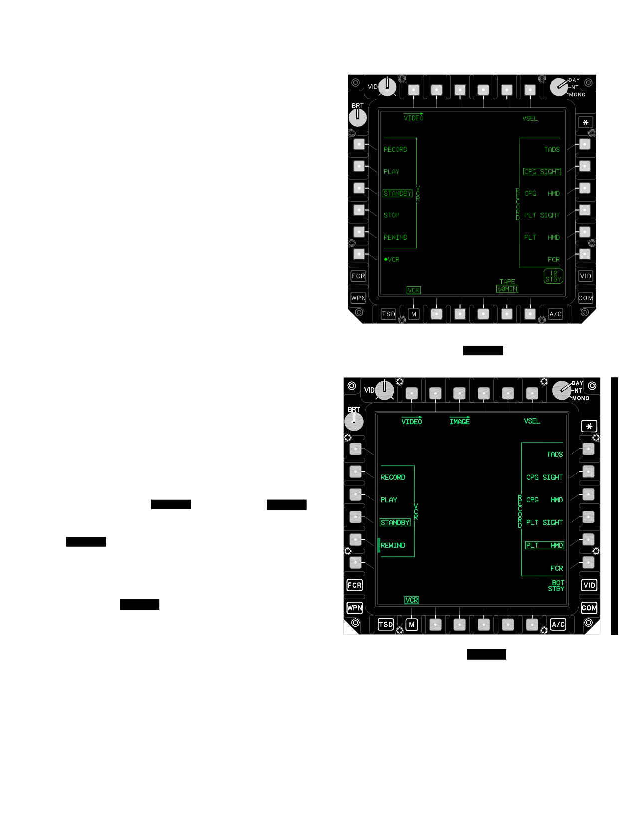
TM 1-1520-251-10
4.53.6 DISPLAY Buttons. The DISPLAY buttons pro-
vide selection of the video source to be displayed (under-
laid) beneath the MPD pages. Video underlay is overrid-
den by selection of the VCR playback, and FCR page
presentation on that MPD. Once these conditions change,
the previously selected video underlay returns to that
MPD. If the selected sight is FCR and FCR is operating in
terrain profiles or RMAP mode, FCR imagery is pres-
ented. During single DP operation, the VIDEO PAGE
selection of PILOT HMD or CPG HMD will continue to
present dual DP display format and imagery (see para
4.50.3).
4.53.7
RESET Button. The reset button allows the
crew to quickly return the VIEW, SHARP, and COLOR
buttons to their default conditions of NORM, no SHARP,
and color WHITE.
4.53.8 SYMB Button. The SYMB button is used to se-
lect between NORM and BOOST to optimize symbol con-
trast. Video performance is best when set to NORM. Set-
LBA−2031
ting the SYMB button to BOOST will darken the video
Figure
4-65.
[
BLK 1
VCR Page]
underlay to boost the apparent symbol brightness.
4.53.9 G/S (Grayscale) Button. Selection of the G/S
button temporarily overrides the VIEW button setting, and
presents VIEW WIDE video with gray scale bars filling the
top and bottom blank video area. If there is currently no
video underlay presented, an additional grayscale pattern
is generated by the CDP for presentation in the center
area. The G/S is useful for understanding the affect the
VID enhancement knob has on video.
4.54 VCR PAGE
The VCR page ( [
BLK 1
fig 4-65] and [
BLK 2
fig
4-65A] ) is used to control the selection of sources for tape
recording, and the VCR operating mode controls.
[
BLK 1
During single DP operation, the video recorder
is off and not selectable. When in single DP operation, or
if the VCR has been identified as failed, the VCR page will
blank, presenting a center status window stating VCR
NOT AVAILABLE and showing the VCR power button on
L6 as OFF.] [
BLK 2
During single DP operation, the vid-
eo recorder is not selectable. When in single DP opera-
tion, or if the VCR has been identified as failed, the VCR
page will blank, presenting a center status window stating
VCR NOT AVAILABLE.]
Figure
4-65A.
[
BLK 2
VCR Page]
Use or disclosure of this information is subject to the restriction(s) on the title page of this document.
Change 3
4-71
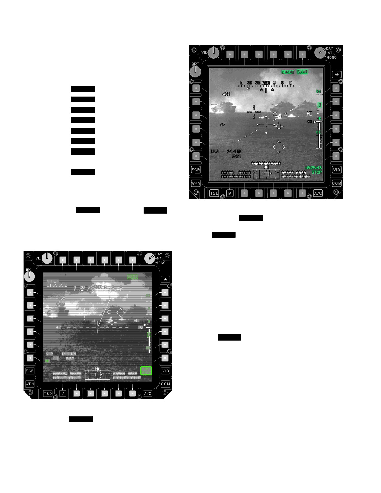
TM 1-1520-251-10
The following selections are found on the VCR page
(VSEL not selected) for all modes of operation:
• T1
VIDEO button
• T6
VSEL button
• L1
[
BLK 1
VCR RECORD button]
• L2
[
BLK 1
VCR PLAY button]
• L2
[
BLK 2
VCR RECORD button ]
• L3
[
BLK 1
VCR STANDBY button]
• L3
[
BLK 2
VCR PLAY button]
• L4
[
BLK 1
VCR STOP button]
• L4
[
BLK 2
VCR STANDBY button]
• L5
VCR REWIND button
• B5
[
BLK 1
TAPE button]
4.54.1 VIDEO Button. Selection of the VIDEO button
from the VCR page calls the VIDEO page.
4.54.2 VSEL Button. Selection of the VCR VSEL (vid-
LBA−5246
eo select) button ( [
BLK 1
fig 4-66] and [
BLK 2
fig
4-66A] ) selects video and its symbology for primary dis-
Figure 4-66A.
[
BLK 2
VCR Page, VSEL Selected]
play, and hides the MPD button labels from display for the
selecting crew station. This button is useful for viewing de-
4.54.3 [
BLK 1
VCR Mode Buttons. The VCR mode
cluttered VCR Playback information on the MPD.
buttons allow moding of the VCR for RECORD, PLAY,
STANDBY, STOP, and REWIND. They are presented
whenever the VCR is available (not failed) during normal
DP operations, and the VCR page is not operating in de-
cluttered mode. The default selection is VCR MODE
STOP (the tape is unthreaded) when operating under ex-
ternal power, and STANDBY (the tape is threaded), when
operating under aircraft power. If at any time the VCR is
unable to enter the commanded state, it will enter an un-
threaded STOP condition from which the crew can send it
to PLAY, RECORD, REWIND, or the threaded STANDBY
condition.]
4.54.3A [
BLK 2
VCR Mode Buttons. The VCR
mode buttons allow moding of the VCR for RECORD,
PLAY, STANDBY, and REWIND. They are presented
whenever the VCR is available (not failed) during normal
DP operations, and the VCR page is not operating in de-
cluttered mode. The default selection is VCR MODE
STANDBY (the tape is unthreaded) when operating under
external power, and STANDBY (the tape is threaded),
when operating under aircraft power. If at any time the
LBA−5070
VCR is unable to enter the commanded state, it will enter
an unthreaded STOP condition from which the crew can
Figure
4-66.
[
BLK 1
VCR Page, VSEL Selected]
send it to PLAY, RECORD, or REWIND.]
Use or disclosure of this information is subject to the restriction(s) on the title page of this document.
4-72
Change 3
TM 1-1520-251-10
4.54.4 [
BLK 1
TAPE Length Button. Selection of
NOTE
the TAPE button toggles between 40 minutes and 60 min-
Voice playback may not be audible to crew
utes. Tapes record for approximately twice their labeled
and/or maintenance personnel following re-
length. Tape length can also be set at the Load Mainte-
placement/reinstallation of the CIU until the
nance Panel. This button affects the elapsed time indica-
VCR volume ON/OFF knob has been
tion and does not alter actual recording speed or time
cycled.
available.]
4.54.6
VCR Playback Operations. Selecting the
4.54.5
VCR Recording Operations. The following
PLAY button initiates play of video tape at normal speed
additional selections can be found on the VCR page (fig
to any MPD presenting the VCR page. If at the end of the
4-65) during all VCR modes of operation except PLAY.
tape, the VCR will mode to [
BLK 1
play reverse] [
When commanded, the VCR records the selected image
BLK 2
play fast reverse] in response to crewmember
source with its symbology overlay. In addition, the approx-
play request by selecting the PLAY button, labelled PLAY
imate zulu time and a format ownership cue (C - FLT, P -
REVERSE at that point in time. The following selections
FLT, TADS, C - FCR, or P - FCR) are also recorded in the
can also be found on the VCR page during VCR Playback:
upper left corner of the format.
• L6
[
BLK 1
Mark (MK) button (VCR ON/
• L6
[
BLK 1
Mark (MK) button (VCR ON/
OFF button)]
OFF button)]
• L6
[
Mark (MK) button]
• L6
[
BLK 2
Mark (MK) button]
BLK 2
• R1
RECORD TADS button
• R1
PLAY Fast Forward (>>) button
• R2
RECORD CPG SIGHT button
• R2
PLAY Forward (>) button
• R3
RECORD CPG HMD button
• R3
PLAY Pause (*) button
• R4
RECORD PLT SIGHT button
• R4
[
BLK 1
PLAY Reverse (<) button]
• R5
RECORD PLT HMD button
• R4
[
BLK 2
PLAY Reverse (<<) button]
• R6
RECORD FCR button
• R5
[
BLK 1
PLAY Fast Reverse (<<)
button]
• B2
EVENT PAUSE/IGNORE button
• R6
[
BLK 1
ORT PLAYBACK button
a. RECORD Buttons. Composite video, containing
(CPG Station Only)]
both imagery and flight, weapon, or FCR
symbology is
recorded in accordance with the RECORD buttons. Zulu
• R6
[
BLK 2
CTR DISP button (CPG
time is also recorded in the upper left area of the format.
Station Only)]
The default selection for these buttons is RECORD CPG
• B2
EVENT PAUSE/IGNORE button
SIGHT. VCR recording can also be commanded on the
left hand grip. See section 4.52.1.
a. ORT PLAYBACK Button. Selection of this but-
ton sends VCR playback to the ORT head-out and head-
b.
[
BLK 1
MARK (MK) Button. Activation of the
down displays ( [
BLK 1
fig 4-67] and [
BLK 2
fig
MARK button marks a particular event on the video tape.
4-67A] ) when the VCR page is presented on either CPG
An event marker tone ( para 4.54.6.c) can be heard at this
MPD.
location when operating in the playback mode.]
b. Center Display
(CTR DSPL) Button (TE-
b1. [
BLK 2
MARK (MK) Button. Activation of the
DAC). Selection of the CTR DSPL button sends VCR
MARK button marks a particular event on the video tape.
playback to the TDU (fig 4-67A) when the VCR page is
(See para 4.54.6.c) ]
presented on either CPG MPD.
Use or disclosure of this information is subject to the restriction(s) on the title page of this document.
Change 4
4-72.1
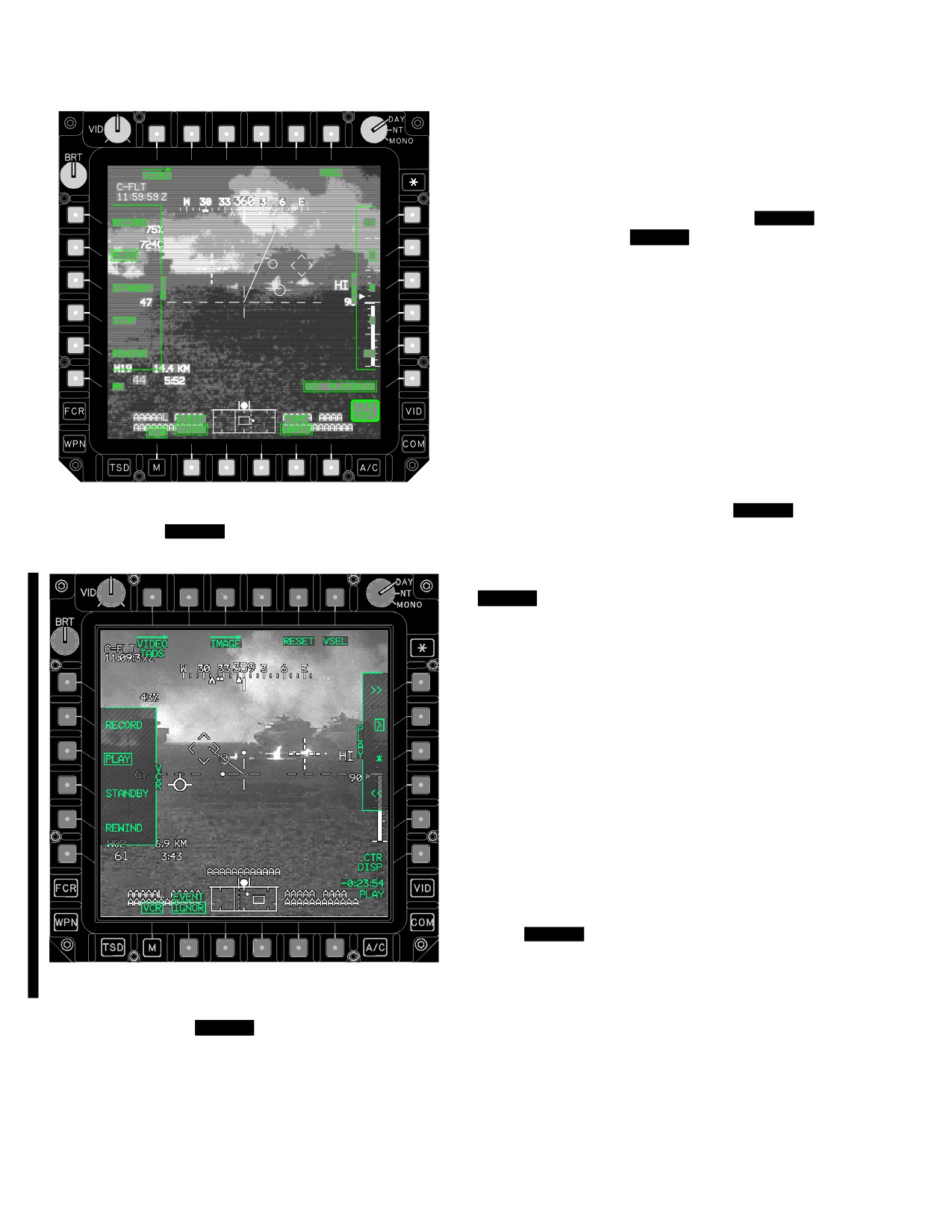
TM 1-1520-251-10
PAUSE, the recorder pauses during tape playback at
each event marker. When set to IGNOR, the recorder ig-
nores event marks during tape playback.
NOTE
When the VCR is operated in the [
BLK 1
STBY Mode] [
BLK 2
STBY threaded
Mode] , the VCR is commanded to PLAY for
one second every five minutes (This is an
auto-advance command that reduces po-
tential damage to the VCR tape/head.) Any
previously recorded audio that is on the tape
is subject to being heard by the flight crew
for that one - second - time period. (If the re-
spective crewmember’s communication
(COMM) panels VCR volume control knob
is pushed in.) To preclude hearing any pre -
recorded audio when operating the VCR in
the STBY mode, pull out the VCR volume
control knob.
LBA3012A
4.54.7 VCR Standby Operations.
[
BLK 1
Selection
Figure
4-67.
[
BLK 1
CPG VCR Page - Play Mode]
of the VCR Mode STANDBY button sets the VCR to
standby. In this mode, the tape is threaded and prepared
for recording or playback.]
[
BLK 2
Selection of the VCR Mode STANDBY button
sets the VCR to either standby or stop depending on the
following conditions. In this mode, the tape is threaded
and prepared for recording or playback.]
• the aircraft is on the ground
• throttles are in OFF
• TADS is OFF
• PNVS is OFF
If all of the above conditions are met, then the VCR is
moded to stop. In this mode, the tape is unthreaded and
will require approximately 3 seconds to thread and begin
to operate as commanded. Otherwise, selection of the
VCR Mode STANDBY button sets the VCR mode to
standby. In this mode, the tape is threaded and prepared
for recording or playback (within half a second).
a.
[
BLK 1
VCR Power Button. The VCR button
allows the crew to power the recorder on and off. The
LBA5072A
VCR will power on automatically unless external power is
applied. The VCR will be commanded to STOP when the
last of the following conditions are met:
Figure
4-67A.
[
BLK 2
CPG VCR Page - Play
• the aircraft is on the ground
Mode]
• throttles are in OFF
• TADS is OFF
c. EVENT Button. Selection of the EVENT button
toggles it between IGNOR and PAUSE. When set to
• PNVS is OFF
Use or disclosure of this information is subject to the restriction(s) on the title page of this document.
4-72.2
Change 3
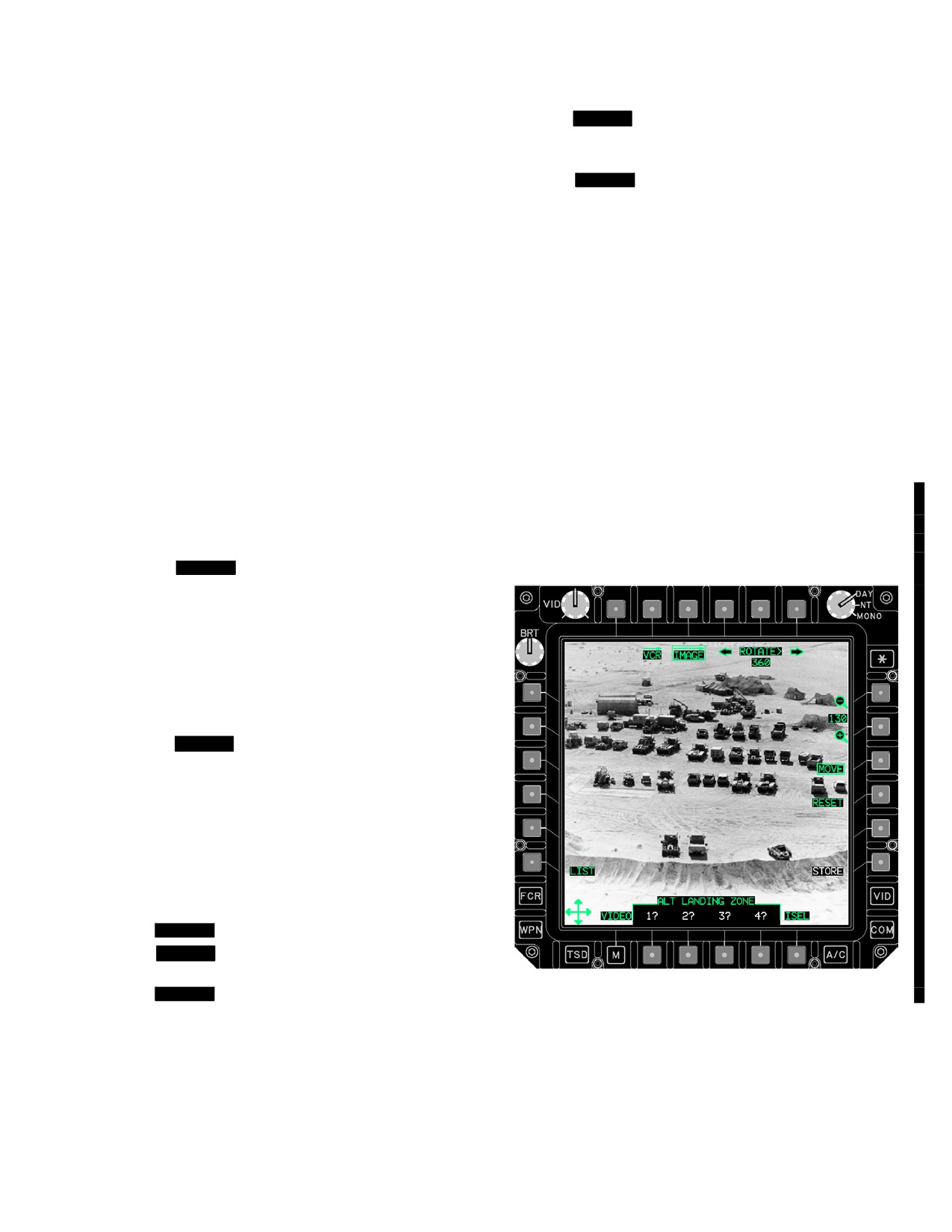
TM 1-1520-251-10
Prior to shut-down of the aircraft, the crewmember should
• [
BLK 2
STOP (VCR mode indicated as STAND-
mode the VCR to OFF.]
BY - tape unthreaded) ]
• RWND
b. Video Tape Counter. A video tape counter, dis-
• [
BLK 1
OFF]
playing tape elapsed time or tape position, and VCR mode
and error messages is presented in the lower right corner
If the state is unknown, a WHITE “?” is presented.
of the VCR page. This counter is not removed during de-
c. VCR Real-Time Video Cue. When real-time vid-
cluttered operation. The counter outline is WHITE whenever
eo underlay is visible on the VCR page, the Video Cue
its interior text strings are white or alternate with white text.
data field, located next to the VIDEO button or VIDEO la-
NOTE
bel on the Menu button, shows which video is being un-
derlaid. This data field is presented to distinguish between
Priority for the presentation of the top line
playback and real-time video. Real-time video cues are:
Counter messages is:
•
CPG SIGHT (CPG)
• FAIL (VCR not responding or failed)
• PLT SIGHT (PLT)
• WET (alternating with other message)
• CPG HMD (CHMD)
• PLT HMD (PHMD)
• CHK (Check VCR)
• TADS (TADS)
• BOT (Beginning of Tape)
4.54A IMAGE PAGE
• EOT (End of Tape)
The IMAGE page (fig 4-67B) allows selection of a data
• Elapsed Time
frame (scanned image). The image selection is used to
view a loaded image (e.g. radar site target).
(1)
[
BLK 1
Top Line. The elapsed time in-
dication provides the same number for the same tape
position consistently (assuming the same tape length
selection), and can be used as a reference during play-
back. When starting from BOT, it may take up to 5 minutes
for the count to change upon initiating RECORD or PLAY.
The VCR can record when moisture is detected (WET).
However, continued operation could damage the VCR.
FAIL, WET, and CHK are displayed as WHITE in color.]
(2)
[
BLK 2
Top Line. The elapsed time indi-
cation can be used as a reference during playback. The
VCR can record when moisture is detected (WET). How-
ever, continued operation could damage the VCR. FAIL,
WET, and CHK are displayed as WHITE in color.]
(3) Bottom Line. The counter also displays a
second data field reflecting the state of the recorder:
• PLAY
• RCD
• [
BLK 1
STBY ]
• [
BLK 2
STBY (VCR mode STANDBY - tape
threaded) ]
• [
BLK 1
STOP]
Figure 4-67B. IMAGE Page
Use or disclosure of this information is subject to the restriction(s) on the title page of this document.
Change 3
4-72.3
TM 1-1520-251-10
The following unique selections are found on the IMAGE
4.54A.1 Image ROTATE Button Left. The Image RO-
page (ISEL not selected) for all modes of operation:
TATE Button Left (T4) is used to rotate the backg2round
image counterclockwise. Selecting the Image ROTATE
Button Left will cause the image to rotate 1 degree. If the
• T3
IMAGE button
Image ROTATE Button Left is selected and held for more
• T4
Image ROTATE button Left
than 0.5 seconds, the image will rotate at 40 degrees per
second after the initial 1 degree rotation.
• T5
Image ROTATE Data Entry button
4.54A.2 Image ROTATE Data Entry Button. The
• T6
Image ROTATE button Right
Image ROTATE Data Entry Button (T5) is used to rotate
• L6
Image LIST button
the image via a crewmember input on the KU. Rotation
angles from 1 through 360 degrees may be used.
• R1
Image Zoom Out button
4.54A.3 Image ROTATE Button Right. The Image
• R2
Image Zoom In button
ROTATE Button Right (T6) is used to rotate the back-
• R3
Image MOVE button
ground image counterclockwise. Selecting the Image RO-
TATE Button Right will cause the image to rotate 1 de-
• R4
Image RESET button
gree. If the Image ROTATE Button Right is selected and
held for more than 0.5 seconds, the image will rotate at 40
• R6
Image STORE button
degrees per second after the initial 1 degree rotation.
• B2
Image view option 1
4.54A.4 LIST Button. The LIST maintained option button
• B3
Image view option 2
(L6) (fig 4-67C ) is used to select which image is to be
viewed. When the list button is selected up to 20 image files
• B4
Image view option 3
will be available from the DTC. Page buttons are displayed if
more than 10 image files are found on the DTC. The first 22
• B5
Image view option 4
characters of the individual file names for each image will be
• B6
ISEL button
displayed. Selection of a file name will load the image.
Use or disclosure of this information is subject to the restriction(s) on the title page of this document.
4-72.4
Change 3
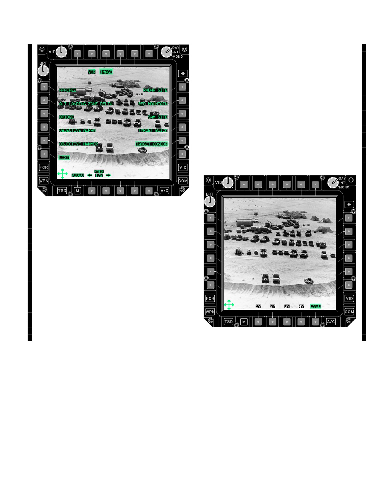
TM 1-1520-251-10
4.54A.9 STORE Button. Selecting the STORE button
(R6) allows the crewmember to store the current image
settings (location, rotation, and zoom) into view.
4.54A.10 Image View Buttons. Selecting any of the
Image View buttons (B2 - B5) allows the crew member to
select up to 4 stored views of the image. Each view con-
tains a specified zoom factor, location, and rotation of the
image. A view is created using the STORE button and se-
lecting the store location 1 - 4.
4.54A.11 ISEL Button. Selection of the ISEL (image
select) button (B6) (fig 4-67D) allows the crew member to
select a decluttered view of the image. All symbols and
controls are removed from the IMAGE page with the ex-
ception of the cursor controller symbol and the image view
buttons 1 - 4.
Figure 4-67C. IMAGE Page / LIST Selected
4.54A.6 ZOOM Buttons. The ZOOM scroll buttons
(R1 - R2) are used to zoom the image in or out. Selecting
an arrow will fine tune the zoom. Holding the arrow button
will change the zoom at a variable rate. Valid zoom range
is from 50% to 400%.
4.54A.7 MOVE Button. Selecting the MOVE button
(R3) allows the crewmember to move the image with the
cursor thumb - force controller.
4.54A.8 RESET Button. Selecting the RESET button
(R4) allows the crewmember to restore the image to the
default (non - stored) view. The default view restores the
image to 100% zoom, 360 rotation angle (image top to
MPD top) and the image will be recentered on the MPD.
Figure 4-67D. IMAGE Page / ISEL Selected
Use or disclosure of this information is subject to the restriction(s) on the title page of this document.
Change 3
4-73
TM 1-1520-251-10
4.55 SIGHTING SUBSYSTEM OPERATING
3. PLRT B/S switch - Check polarity reversal.
PROCEDURES
4. NVS MODE switch - NORM.
4.55.1 IHADSS Boresight - Pilot and CPG.
5. Registration - Check.
WARNING
a. Align crewmembers LOS forward to the 12
o’clock position ±5°.
OFFSET boresight is not authorized.
b. Select a reference object approximately 90
NOTE
ft in front of the aircraft.
Checks herein are in addition to those listed
c. Check registration (alignment differential)
in chapter 8. Except for safety, chapter 4
between the thermal image and reference
does not duplicate chapter 8 checks.
object in azimuth and elevation.
1.
Sight select switch - HMD.
d. The allowable registration error is 1 ft of azi-
muth at 90 ft. The center open position of
2.
WPN page - GRAYSCALE button - Select.
the LOS reticle is equivalent to 1 ft at 90 ft.
3.
BRT and CONT knobs - Adjust as desired.
e. Unity Magnification - Check. Ensure 1:1 ra-
a. Sizing and centering - Verify.
tio with selected object.
6. Alternate sensor - Check.
b. Infinity focus - Check.
4.55.3 TADS Operational Checks - CPG (ORT).
4.
WPN Page - GRAYSCALE button - Deselect.
5.
SYM BRT Control (ORT and pilot) or SYM
CAUTION
brightness (TEDAC) - Adjust as desired.
The FLIR zoom field-of-view shall not be
6.
WPN page - BORESIGHT button - Select.
activated for more than one minute of
continuous operation to prevent exces-
7.
IHADSS button - Select.
sive after - image or raster burn. Any use
of the FLIR zoom FOV will result in some
8.
PRI INT LT knob - Adjust as desired.
amount of after-image or raster burn.
The after - image tends to fade out over
9.
HMD reticle - Align with BRU.
operating time in other FLIR FOV’s. How-
ever, prolonged use of FLIR zoom FOV
10.
PLRT B/S switch - B/S and release.
will result in an increased amount of
B/S NOW button (aircraft equipped with MTADS
after image or raster burn.
provisions) - Select.
1. NVS MODE switch - OFF
11.
BORESIGHT button - Deselect.
2. Sight select switch - TADS.
12.
PRI INT LT knob - Adjust as desired.
3. VID SEL switch - TADS.
4.55.2 NVS Operational Check (Pilot and CPG).
4. GS switch - Press.
1. NVS MODE switch - FIXED or NORM.
2. GAIN and LVL knob (ORT and pilot) or GAIN
5. BRT and CONT knob - Adjust as desired on
and LEV (TEDAC) - Adjust for optimum image.
heads - up and heads - down displays.
Verify capability to select the various modes of
flight symbology.
6. VID SEL switch - TADS.
Use or disclosure of this information is subject to the restriction(s) on the title page of this document.
4-74
Change 4
TM 1-1520-251-10
7.
Sensor Select switch - DTV.
4.55.3A TADS Operational Checks - CPG (TEDAC).
8.
SLAVE switch - Press and release to initiate
CAUTION
manual track.
The FLIR zoom field-of-view shall not be
activated for more than one minute of
9.
MAN TRK thumbforce controller - Exercise tur-
continuous operation to prevent exces-
ret.
sive after - image or raster burn. Any use
of the FLIR zoom FOV will result in some
amount of after-image or raster burn.
10.
TADS FOV switch - Evaluate various FOVs.
The after - image tends to fade out over
operating time in other FLIR FOV’s. How-
ever, prolonged use of FLIR zoom FOV
11.
IAT/OFS switch - Engage. Check for proper
will result in an increased amount of
function.
after image or raster burn.
1.
NVS MODE switch - OFF.
12.
Sensor Select switch - DVO.
2.
Sight select switch - TADS.
13.
TADS FOV switch - Evaluate various FOVs. If
3.
TAD - selected.
scene is not vertical in both FOVs, perform
Pechan Alignment.
4.
G/S - selected.
14.
Sensor Select switch - FLIR.
5.
BRT ans CON buttons - adjust as desired.
6.
TAD - selected.
15.
GAIN and LVL knob - Adjust for optimum image
then engage ACM as desired.
7.
Sensor select switch - DTV.
8.
SLAVE switch - Press and release to initiate
16.
TADS FOV switch - Select. Evaluate various
manual track.
FOV’s.
9.
MAN TRK thumbforce controller - Exercise tur-
ret.
17.
IAT/OFS switch - Engage image auto tracker.
Check for proper performance.
10.
TADS FOV switch - Evaluate various FOVs.
11.
IAT/OFS switch - Engage. Check for proper
18.
FLIR PLRT button - Check polarity.
function.
12.
Sensor Select switch - FLIR.
19.
Sensor Select switch - DTV or FLIR.
13.
GAIN and LEV knobs -Adjust for optimum
image, then engage ACM as desired.
NOTE
14.
TADS FOV switch - Select. Evaluate various
If Auto Drift Null does not reduce drift to
FOV’s.
desired level, perform Manual Servo Drift
Null Procedure. Manual Servo Drift Null may
reduce TADS turret slew rates by up to 50%.
15.
IAT/OFS switch - Engage image auto tracker.
Check for proper performance.
20. Drift null - Perform if required.
16.
FLIR PLRT button - Check polarity.
Use or disclosure of this information is subject to the restriction(s) on the title page of this document.
Change 3
4-75
TM 1-1520-251-10
17. Sensor Select switch - DTV or FLIR.
11. Right Thumbwheel Control - Adjust as required
to align horizontal crosshair with horizon.
NOTE
12. Boresight Enable switch - CENTER.
If Auto Drift Null does not reduce drift to
desired level, perform Manual Servo Drift
13. TADS FOV switch - N.
Null Procedure. Manual Servo Drift Null may
reduce TADS turret slew rates by up to 50%.
14. NFOV - Reverify alignment.
18. Drift null - Perform if required.
NOTE
NOTE
If satisfactory, procedure is complete. If not
satisfactory, repeat steps 5 through 14 as
If satisfactory, procedure is complete. If not
required.
satisfactory, repeat steps 5 through 14 as
required.
4.55.5 TADS Manual Servo Drift Null (ORT).
4.55.4 TADS Pechan Realignment (ORT).
1. Sight select switch - TADS.
1. Sight select switch - TADS.
2. SLAVE switch - Press to verify TADS turret
slews to fixed forward position by observing
2. Sensor Select switch - DVO.
dashed reticle in center of display.
3. TADS FOV switch - N.
3. SLAVE switch - Press.
4. TADS turret - MANUAL control.
4. Sensor select switch - DTV or FLIR (for greatest
accuracy use DTV).
5. Boresight Enable switch - UP.
5. TADS FOV switch - N.
6. Left Thumbwheel Control - Adjust as required to
align horizontal crosshair with horizon.
6. Reticle - Aim at easily observed object.
7. Boresight Enable switch - CENTER.
7. Boresight Enable switch - UP. Wait 5 seconds
then adjust left and right thumbwheel controls
8. TADS FOV switch - W.
for drift null.
9. Crosshair and horizon - Recheck alignment.
8. Boresight Enable switch - CENTER.
NOTE
NOTE
If satisfactorily aligned, select desired oper-
If the manual procedure was accomplished,
ating mode. If not satisfactorily aligned, go
the auto drift null may may be reactivated by
to step 10.
placing the Boresight Enable switch in UP
position for 2 seconds and then placing it
10. Boresight Enable switch - UP.
back to CENTER position.
Use or disclosure of this information is subject to the restriction(s) on the title page of this document.
4-76
Change 3
TM 1-1520-251-10
4.55.5A TADS Manual Servo Drift Null (TEDAC).
4.55.6 TADS Internal Boresight (ORT).
WARNING
1. Sensor select switch - FLIR or TV.
Proper laser safety procedures shall be
followed.
NOTE
2. TADS FOV switch - N.
• Boresighting of the DTV and FLIR occur
independently and the actual order is not
critical. However, DTV must be bore-
3. SLAVE switch - Press and release to initiate
sighted prior to boresighting the DVO.
manual track. Observe TADS drift.
• Internal boresight errors can develop in
flight due to temperature changes within
the internal components of the TADS
(thermal drift). It is recommended that an
NOTE
internal boresight be accomplished 2
times per 2.5 hour flight. Generally, the
more recent the internal boresight, the
To set TEDAC Display Unit (TDU) default
more accurate the system will be.
brightness and contrast levels, press AZ/EL
button on TDU.
1.
Sight select switch - TADS.
2.
WPN UTIL - LASER on.
4. AZ/EL button - Press to activate servo drift null.
3.
WPN page - BORESIGHT - Select.
AZ/EL will appear boxed above button. After five
seconds, AZ and EL buttons become active.
4.
INTERNAL - Select. Internal boresight mes-
sage present - Verify.
5.
LASER - ARM.
NOTE
6.
Sensor select switch - DTV.
If elevation and azimuth servo drift is not
7.
TADS FOV switch - N.
corrected, go to step 5. Otherwise, go to
step 7.
8.
IAT polarity switch - W.
9.
LRFD trigger - Press and hold, observe pres-
ence of laser spot.
5. Adjust AZ and EL buttons to center target on
TADS reticle.
10.
Boresight Enable switch - UP. Observe tracking
gates capture laser spot. Continue to fire laser
until tracking gates disappear. If tracking gates
fail to capture laser spot, perform manual bore-
6. AZ/EL button - Press. AZ/EL display box above
sight (para 4.55.9) as required. If tracking gates
button will extinguish.
enter STOP mode, Boresight Enable switch to
CENTER position, then back to UP position.
11.
Boresight Enable switch - CENTER.
7. SLAVE switch - Press to deactivate manual
track.
12.
LRFD trigger - Release.
Use or disclosure of this information is subject to the restriction(s) on the title page of this document.
Change 3
4-77
TM 1-1520-251-10
13.
TADS FOV switch - Z.
29. Boresight Enable switch - CENTER.
14.
Z FOV - Repeat steps 9 through 12, then pro-
30. LASER - SAFE.
ceed to step 15.
31. BORESIGHT button - Deselect.
15.
Sensor select switch - FLIR.
32. WPN UTIL Page - Deselect LASER if desired.
16.
TADS FOV switch - N.
4.55.6A TADS Internal Boresight (TEDAC).
17.
LVL - Adjust fully counterclockwise.
18.
GAIN - Adjust to mid-range.
WARNING
19.
LRFD trigger - Press and hold.
Proper laser safety procedures shall be
Observe laser spot, and optimize FLIR for white
followed.
laser spot. If laser spot is not visible, perform
FLIR Cue Update Procedure
1. DTV Boresight NFOV
(para 4.55.7).
a. WPN page - Laser ON.
20.
Boresight Enable switch - UP. Observe tracking
gates capture laser spot. Continue to fire laser
b. WPN page - Select Boresight.
until tracking gates disappear. If tracking gates
fail to capture laser spot, perform manual bore-
c. TADS BORESIGHT page - TADS INTER-
sight (para 4.55.9). If tracking gates enter STOP
NAL - select.
mode, Boresight Enable switch to CENTER
position, then back to UP position.
WARNING
21.
Boresight Enable switch - CENTER.
Do not allow personnel forward of the
22.
LFRD trigger - Release.
TADS interface bulkhead while the laser
is being fired. Direct exposure to or re-
23.
TADS FOV switch - Z.
flections from the laser beam could
cause blindness or serious eye injury.
24.
Z FOV - Repeat steps 19 through 22, then pro-
ceed to step 25.
NOTE
25.
Sensor select switch - DVO.
To set TEDAC Display Unit (TDU) default
brightness and contrast levels, press * but-
26.
TADS FOV switch - N. Observe position of DVO
ton on TDU.
crosshairs. If the DVO crosshairs are not clearly
visible, perform DVO CUE update procedure
d. LASER - ARM.
(para 4.55.8). Observe position of DVO cross-
hairs. If coincident with DTV reticle, go to step
29.
e. Laser Trigger switch - Press and hold at
second detent. Verify laser spot is visible on
27.
Boresight Enable switch - DOWN.
TDU.
28.
DVO BRSIT - Adjust DVO crosshairs into coin-
f. AZ/EL button - press to enable boresight.
cidence with DTV reticle.
AZ/EL will appear in box above button.
Use or disclosure of this information is subject to the restriction(s) on the title page of this document.
4-78
Change 3
TM 1-1520-251-10
g. On TDU, observe that the tracker gates
f. On TDU, observe that tracker gates capture
capture the laser spot and center it in the
laser spot and center it in the display aiming
display aiming reticle. If laser spot is not
reticle. If laser spot is not centered on the
centered on the display and cannot be cap-
display and cannot be captured by tracking
tured by tracking gates, press AZ/EL button
gates, press AZ/EL button to enable AZ/EL
and continue firing laser. Wait five seconds
buttons and continue firing the laser. Wait
and adjust AZ and EL controls to center la-
five seconds and adjust AZ and EL controls
ser spot in display. Release laser trigger and
to center laser spot in display. Release laser
repeat steps e through i. If tracker enters the
trigger switch and repeat steps d through f.
STOP mode, press AZ/EL switch and re-
If tracker enters the Stop Mode, press AZ/
peat steps e through i.
EL switch and repeat steps d through f.
h. When tracker gates disappear, press AZ/EL
button to disable boresight. AZ/EL display
g. When tracking gates disappear, press AZ/
box above button will extinguish.
EL button to disable boresight. AZ/EL box
above button will extinguish.
i. Laser trigger - Release.
2.
DTV boresight ZFOV.
h. Laser trigger - Release.
a. TADS FOV switch - Z.
b. Repeat steps - 1.e through 1.12 to bore-
4.
FLIR Boresight ZFOV.
sight zoom FOV.
3.
FLIR Boresight NFOV.
CAUTION
a. Sensor select switch - FLIR.
b. FLIR polarity switch - Press to select white
FLIR zoom FOV shall not be actuated for
hot.
more than two minutes of continuous
operation in order to prevent excessive
c. TADS FOV switch - N.
raster retention. Permanent damage may
occur if it is engaged for more than five
d. Laser trigger
- Press and hold at second
minutes.
detent. Adjust GAIN and LEV controls for
brightest laser spot with least backg2round
noise. If laser spot is not visible or if laser
spot is visible and cannot be captured in
a. TADS FOV switch - Z.
step f below, perform FLIR CUE Update
Procedure (para 4.55.7A) and select a dif-
ferent aiming reticle position within the CUE
b. Repeat steps 3.d through 3.22.
update target boundaries.
e. AZ/EL button - Press. AZ/EL will appear
boxed above switch.
c. TADS FOV switch - FOV other than Zoom.
Use or disclosure of this information is subject to the restriction(s) on the title page of this document.
Change 3
4-78.1
TM 1-1520-251-10
4.55.6B [
MT
MTADS Internal Boresight].
5. Laser WARNING and prompts - observe safety
procedures and boresight procedure prompts.
WARNING
6. LASER - ARM.
Proper laser safety procedures shall be
7. LRFD trigger - Press and hold, observe pres-
followed.
ence of laser spot on the TDU or ORT HOD.
Continue lasing until spot disappears or DTV
NOTE
boresight is complete.
• Automatic internal boresighting of the
DTV and FLIR occur independently with
8. Internal Boresight Status - Observe
DTV being accomplished prior to FLIR. If
an ORT is installed, DTV must be bore-
a. Verify DTV BORESIGHT COMPLETE sta-
sighted prior to boresighting the DVO.
tus.
• If DTV boresight is complete, then FLIR
boresight will be performed. If DTV bore-
b. Continue to monitor FLIR BORESIGHT IN
sight fails, then FLIR boresight will not be
PROGRESS - Verify FLIR BORESIGHT
performed.
COMPLETE status.
• When FLIR boresight is complete, the in-
ternal boresight is complete.
c. If unable to successfully complete bore-
sight, exit internal boresight mode.
• Internal boresight errors can develop in
flight due to temperature changes within
9. BORESIGHT button - Deselect.
the internal components of TADS (ther-
mal drift). It is recommended that an in-
4.55.7 FLIR CUE Update Procedure (ORT).
ternal boresight be accomplished 2 times
per 2.5 hour flight. A HAD sight status
message will be displayed to indicate an
1. Sight select switch - TADS.
internal boresight is required at system
powerup and every 50 minutes thereaf-
2. Sensor select switch - DTV.
ter.
3. TADS FOV switch - W.
1.
WPN UTIL - LASER on.
4. WPN Page - BORESIGHT button - Select.
2.
WPN page - BORESIGHT - Select.
3.
Sensor select switch - DTV or FLIR.
5. INTERNAL button - Select.
4.
INTERNAL - Select. Internal boresight mes-
6. SLAVE switch - Actuate. Verify INTERNAL BS
sage present - Verify.
message replaced by CUE UPDT message.
Use or disclosure of this information is subject to the restriction(s) on the title page of this document.
4-78.2
Change 4
TM 1-1520-251-10
NOTE
7. AZ/EL button - Press.
Reticle should appear within the black
8. SLAVE switch - Press to select internal bore-
cross. If not, execute the following steps:
sight. Verify that INTERNAL BORESIGHT is
displayed in lower left corner of TDU.
7. Boresight Enable switch - UP.
4.55.8 DVO CUE Update Procedure (ORT).
8. DTV reticle - Use thumbforce controller to posi-
tion within black cross.
NOTE
9. Boresight Enable switch - CENTER.
The DVO CUE Update should be accom-
plished whenever the DVO crosshairs are
10. SLAVE switch - Actuate. Verify CUE UPDT
not visible during Internal Boresight. If the
message replaced by INTERNAL BS.
crosshairs are still not visible after accom-
plishing the DVO CUE Update, then pro-
11. WPN Page - BORESIGHT button - Deselect.
ceed with maintenance troubleshooting.
Note that there are symbology indications to
4.55.7A FLIR CUE Update Procedure (TEDAC).
the operator.
1. Sensor select switch - TV.
1. Sight select switch - TADS.
2. TADS FOV switch - W.
2. Sensor select switch - DVO.
3. TADS FOV Switch - W.
NOTE
To set TEDAC Display Unit (TDU) default
4. SLAVE Switch - Press.
brightness and contrast levels, press * but-
5. Manual Thumb Force Controller - Adjust light to
ton on TDU.
center of crosshairs.
3. SLAVE switch - Press to select cue update.
6. TADS FOV Switch - N.
Verify that message CUE UPDT is displayed in
lower corner of TDU.
7. Observe DVO crosshairs. If the visual presenta-
tion is still not optimum - fine tune for best pre-
NOTE
sentation with the Thumb Force controller.
All four cue update target position indicators
8. SLAVE Switch - Press.
may not be visible on the display simulta-
neously.
9. Continue with Internal Boresight.
4.55.9 Manual Boresight (ORT).
4. Observe position of cue update target position
indicators around aiming reticle. If aiming reticle
is not within boundary line or the laser spot is not
NOTE
visible or not useable during FLIR internal bore-
The manual boresight adjust procedure is
sight, go to step 6 , If aiming reticle is within
used only to recapture or center the laser
boundary line go to step 8.
spot. It is not an acceptable boresight pro-
cedure for normal flight operations.
5. AZ/EL button - Press. AZ/EL will appear boxed
above switch.
1. Sight select switch - TADS.
NOTE
2. WPN UTIL page - LASER on.
Do not drive cue update target from the
3. WPN Page - BORESIGHT button - Select.
FOV.
4. INTERNAL button - Select.
6. MAN TRK control - Operate to move aiming re-
ticle within cue update target boundary.
5. LASER button - ARM.
Use or disclosure of this information is subject to the restriction(s) on the title page of this document.
Change 4
4-78.3
TM 1-1520-251-10
6.
Sensor select switch - FLIR or DTV as required.
NOTE
If the target is between 0.5 km and 1.5 km,
7.
FLIR PLRT button - White hot.
the range entered on the KU must be within
10m. If the target is between 1.5 km and 5
8.
TADS FOV switch - N.
km, the range entered on the KU must be
within 50m. If the target is greater than 5
9.
GAIN knob - Adjust to mid-range.
km, the range entered on the KU must be
within 1 km.
10.
LVL knob - Adjust fully counterclockwise.
3. NFOV FLIR - Adjust GAIN and LVL. Observe
11.
LRFD trigger - Press and hold. Observe laser
outfront boresight target for optimum autotrack-
spot and optimize FLIR.
er image. Engage IAT. If tracker enters stop
mode, disengage IAT, then re-engage IAT.
12.
Boresight Enable switch - UP for 1 second, then
move to CENTER position. After 5 seconds the
left and right thumbwheel controls will be active;
4. Sensor select switch
- DTV, observe light
adjust laser spot in elevation and azimuth.
source.
13.
LRFD trigger - Release.
If FLIR and DTV reticles do not strike the bore-
sight target in precisely the same spot, perform
14.
Boresight Enable switch - CENTER.
the following:
15.
LASER - SAFE.
16.
WPN Page - BORESIGHT button - Deselect.
WARNING
17.
WPN UTIL page - Deselect LASER, if desired.
Do not allow personnel forward of the
4.55.10
TADS Outfront Boresight (ORT).
TADS interface bulkhead while the laser
WARNING
is being fired. Direct exposure to or re-
flections from the laser beam could
TADS Outfront Boresight validation and
cause blindness or serious eye injury.
adjustment (if necessary) shall be per-
formed prior to using the TADS FLIR
5. WPN Page - BORESIGHT button - Select.
imagery for laser or weapons opera-
tions, after performing a Cue update, a
TADS component change, or if the heli-
6. OUTFRONT - Select.
copter experiences an abnormal electri-
cal shutdown.
1. Helicopter - Position on the ground over identi-
7. Boresight Enable switch - UP.
fied location for this procedure.
NOTE
8. Adjust azimuth and elevation knobs to center
If on an approved laser firing range, fire la-
the target on the reticle.
ser to obtain range. Otherwise, enter manu-
ally the range from the helicopter to the out-
front boresight target by selecting MAN
9. Boresight Enable switch - CENTER.
RNG on WPN page and entering range in
KU.
2. RANGE - Enter.
10. WPN Page - BORESIGHT button - Deselect.
Use or disclosure of this information is subject to the restriction(s) on the title page of this document.
4-78.4
Change 4
TM 1-1520-251-10
4.55.10A TADS Outfront Boresight (TEDAC).
11. Observe boresight target light source. if not cen-
tered on TADS reticle, complete steps 12
through 18.
WARNING
WARNING
TADS Outfront Boresight validation and
adjustment (if necessary) shall be per-
Do not allow personnel forward of the
formed prior to using the TADS FLIR
TADS interface bulkhead while the laser
imagery for laser or weapons opera-
is being fired. Direct exposure to or re-
tions, after performing a Cue update, a
flections from the laser beam could
TADS component change, or if the heli-
cause blindness or serious eye injury.
copter experiences an abnormal electri-
cal shutdown.
12. WPN page - BORESIGHT - Select.
NOTE
13. WPN page - TADS OUTFRONT - Select.
Wait 30 minutes after the FLIR NOT
14. AZ/EL button - Press. AZ/EL becomes boxed
COOLED message on the TEDAC Display
above button.
Unit (TDU) disappears before performing
outfront boresight. This allows the FLIR sys-
15. AZ and EL buttons - adjust to center target on
tem to stabilize for a more accurate outfront
TADS recticle.
boresight.
16. AZ/EL button - Press. AZ/EL display box above
button will extinguish.
1. NVS switch - OFF.
17. IAT switch - OFF.
2. WPN page Range button - enter manual range
from helicopter to boresight target on KU.
18. WPN page - BORESIGHT - Deselect.
4.55.11 FCR Operational Check
NOTE
NOTE
A target, a minimum of 0.5 km away from
• Wait for magnetic heading scale to ap-
the helicopter is required. The target must
pear before proceeding to power-up the
have the same center as viewed in both
FCR. INU must be aligned before reliable
FLIR and TV sensors.
FCR target information is available.
•
The FCR will not accept DTU loads for
modes and lethal ranges or FCR UTIL
3. Sight select switch - TADS.
page (DTU source) priority schemes D, E
F, or G until the FCR has completed pow-
4. Sensor select switch - FLIR.
er - up BIT and the FCR power button is
not OIP.
5. FLIR LEV and GAIN knobs - Adjust as neces-
• This operational check verifies correct
sary.
operation of the crewstation switches
used to employ the FCR. If it is antici-
6. TADS FOV switch - N.
pated that both the pilot and CPG will op-
erate the FCR during the mission, then
7. Slave button - Press to enable manual track.
this task should be completed in both
crewstations.
8. Exercise TADS Turret with MAN TRK controller
• A WEAPONS/SIGHTS DTU load only
to acquire boresight target.
needs to be performed one time by either
the PLT or CPG.
9. IAT/OFS switch - IAT. Engage boresight target
1.
FCR UTIL page - Select.
with auto tracker.
2.
MMA button - NORM (1st power up, if pinned,
10. Sensor select switch - TV.
or select FCR or RFI power ON).
Use or disclosure of this information is subject to the restriction(s) on the title page of this document.
Change 4
4-78.5
TM 1-1520-251-10
3. FCR - Verify BIT complete; no faults.
11. Left/Right Arrows - Press, verify movement on
TSD.
CPG - SLAVE switch press, verify movement
4. DTC - Load WEAPONS/SIGHTS as required.
with thumb force controller.
5. RFI MODE button - Set.
12. FCR SCAN switch -
6. GND ORIDE switch - ON (if required).
a. Select CS, verify with ”wiper blade” and ra-
dar video.
7. FCR UTIL page - Enter as required:
b. SELECT SS, verify abort of CS.
a. Terrain Mode - Select.
c. Select SS, verify with ”wiper blade” and ra-
dar video.
b. Priority Scheme - Select.
13. LINK switch -
8. Sight Select switch - FCR.
a. Select LINK and verify FCR L message in
HAD, and TADS linked to the FCR NTS tar-
get.
9. FCR SCAN Size - Select M, N, Z, verify
changes, return to W.
b. Terminate LINK by sight selecting FCR,
TADS, or HMD.
10. FCR MODE Switch - Verify ability to select
TPM, ATM, and RMAP. (Remain in RMAP.)
14. GND ORIDE switch - OFF (if required).
Use or disclosure of this information is subject to the restriction(s) on the title page of this document.
4-78.6
Change 4
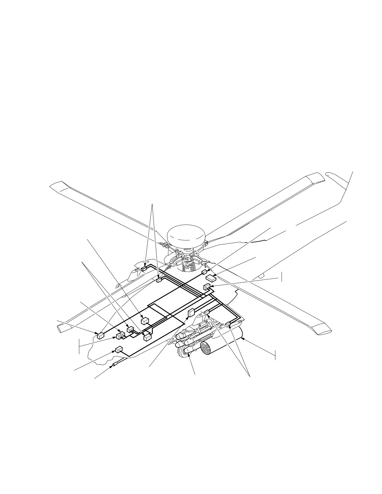
TM 1-1520-251-10
Section II. ARMAMENT SYSTEMS
4.56 GENERAL
controlled by redundant weapon processors which man-
age gun, rocket and missile functions. The weapon sys-
This section provides a description of the armament sys-
tems consists of the following:
tems and respective operating procedures. It includes a
description of weapons components, the controls and dis-
• M139 Area Weapons System (AWS) (M230E1
plays, systems operation, and armament checklists.
Automatic Gun)
4.57 INTRODUCTION
• Rocket Management Subsystem (2.75 Inch Aerial
Rocket)
The armament systems (fig 4-68) provide the aircrew with
a means of quick response delivery of ordnance to se-
• Longbow Hellfire Modular Missile System
lected targets. The armament systems provide for weap-
on selection, control moding, and firing, for close-in, me-
dium and long-range targets. The armament systems are
• Wing Stores Pylon Subsystem
PYLON
INTERFACE UNITS
SIDELOADER
LOAD MAINTENANCE PANEL
MAGAZINE CONTROLLER
WEAPONS
PROCESSORS
HIADC
SYSTEM
PROCESSOR
GUN CONTROL BOX
EG1 2
TURRET
CONTROL
BOX
2.75 INCH
ROCKETS
EG1 1
SYSTEM
PROCESSOR
HELLFIRE/
PYLON
30mm GUN
RF & LASER
INTERFACE UNITS
LBA0094
Figure 4-68. Armament Systems
Use or disclosure of this information is subject to the restriction(s) on the title page of this document.
4-79
TM 1-1520-251-10
4.58 ARMAMENT SYSTEM ARCHITECTURE
attitudes, rates, and accelerations to the WP for use in
ballistic computations and weapons constraint calcula-
4.58.1 PRIMARY POWER CONTROL. Prime power is
tions.
applied to the Hellfire weapon stations when the subsys-
tem is enabled via the WPN UTIL page. The gun prime
4.58.5 Air Data System (ADS). The ADS provides air
power is applied during aircraft powerup and the rocket
data to the WP for use in computing ballistics and weapon
subsystem does not require prime power. The weapon
constraint calculations.
subsystem enable/disable functions on the WPN UTIL
page allow for positive safeing of the weapons suite for
4.58.6 Pylon Interface Units (PIU). Each pylon con-
rearming or other activities that require absolute safeing
tains one PIU. The PIU communicates via the MUX bus to
measures.
control pylon positioning and control, status information
and management of pylon stores.
4.58.2
Arm Power Control. Weapon stations are
armed only after a weapon is selected, via the WAS, and
4.58.7 Weapons Processor (WP). During normal op-
the aircraft has been armed from the ARMAMENT panel
eration, one WP actively provides weapon computations
A/S button.
and control while the second WP is maintained in a readi-
ness state. The WP performs the tasks of weapon initial-
a. The SP controls the application of arm power inde-
ization, selection, inventory, moding, positioning, and fir-
pendent of the WP, in that the aircraft must be armed as
ing for all aircraft weapons.
determined by the SP, before WP station arm power re-
quests are acted upon.
CAUTION
b. Station arm power is applied via the ELCs under
SP control. Electromagnetic relays are used for all weap-
There is no indication in the cockpit
on power load switching. The SP determines the aircraft
when the SQUAT ORIDE switch is in the
state based on the ARMAMENT panel selections and the
AIR position. The possibility exists that
squat switch. The SP commands the ELCs to apply sta-
the AWS could inadvertently be driven
tion arm power when requested by the WP.
into the ground.
c. The WP requests station arm power, via the SP,
4.58.8 Load Maintenance Panel (LMP). The LMP (fig
when the aircraft is armed and a weapon is selected and
4-69) provides the ground crew with the capability to man-
arming constraints are satisfied. Station arm power is
ually enter and display AWS and external stores muni-
used for rocket and missile squib ignition as well as gun
tions load data. The LMP provides the aircrew the capabil-
bolt-pulse relay control.
ity to check/verify rocket type within each of the rocket
zones and gun rounds loaded on pre-flight. A weapon
4.58.3 System Processor (SP). The SP provides the
load page is provided on the MPD to permit aircrews to
SAFE/ARM control and the corresponding primary power
modify (override) the LMP zone inventory in the event an
and arm power control to the weapons.
entry error is made by the load crew during munition load-
ing or LMP failure occurs. The LMP also permits position-
4.58.4 Embedded Global Positioning Inertial Naviga-
ing of the pylons to either +4° (Up) or - 5° (down) positions
tion System (EGI). The EGI provides aircraft position,
for munitions loading.
Use or disclosure of this information is subject to the restriction(s) on the title page of this document.
4-80
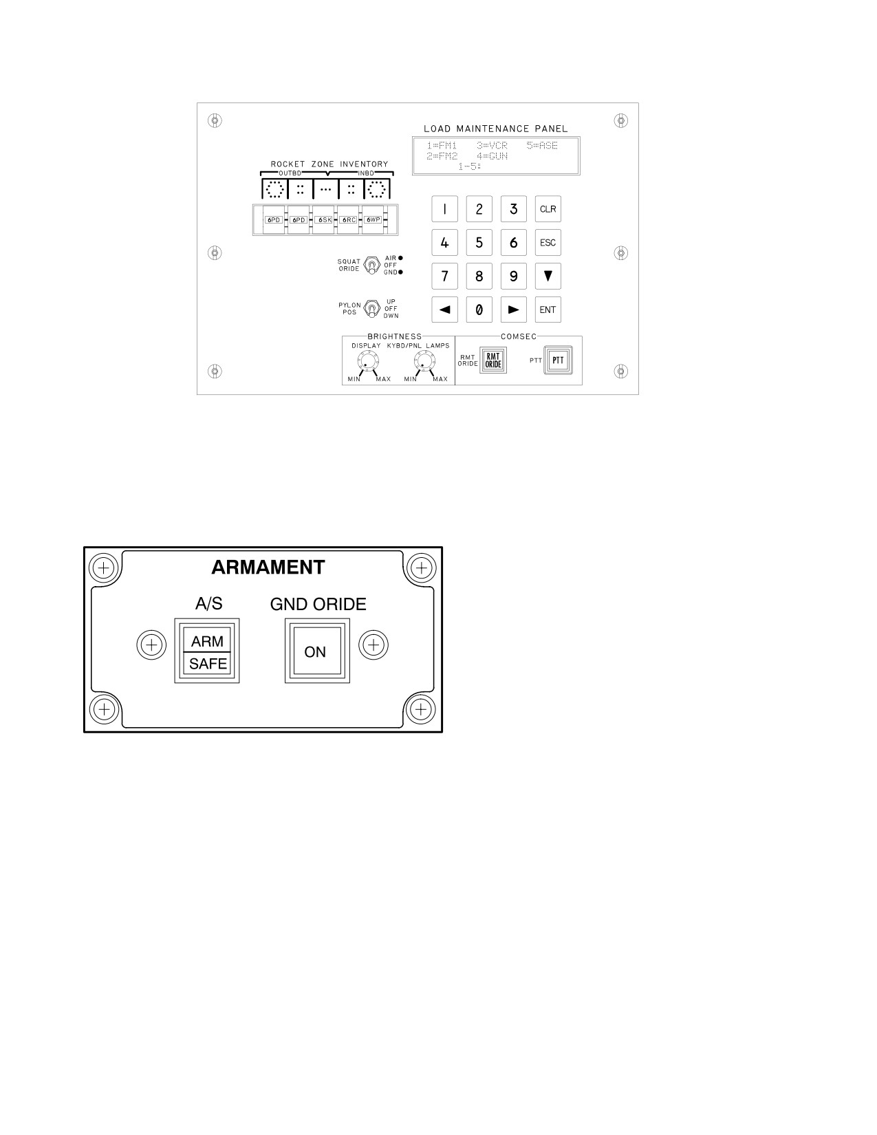
TM 1-1520-251-10
LBA2559
Figure 4-69. Load Maintenance Panel
4.59 ARMAMENT PANEL
between SAFE and ARM. The button light indicates
SAFE or ARM as appropriate in both crew stations. On
The ARMAMENT Panel (fig 4-70) is located on the instru-
aircraft powerup, the default setting is SAFE. There is no
ment panel in both crew stations.
OFF position for the ARM/SAFE button.
4.59.2
Ground Override (GND ORIDE). The GND
Í
Í
ORIDE button is a lighted pushbutton used to override
squat switch inhibits when on the ground. Activating the
Í
Í
GND ORIDE button enables ARM/SAFE control in all
modes and the button light indicates ON in both crew sta-
tions. Activating the button a second time will mode the
GND ORIDE button to OFF and extinguish the ON indica-
tor.
Í
Í
4.60 CYCLIC CONTROL GRIP
Í
Í
Í
The following weapons system controls are located on the
BA0071
cyclic control grip (fig 4-71) in each crew station.
Figure 4-70. ARMAMENT Panel
4.60.1 Weapon Action Switch (WAS). The WAS is a
five-position spring-loaded switch. Placing the switch mo-
4.59.1 ARM/SAFE (A/S) Button. The A/S button is a
mentarily to a desired position selects (actions) a weapon
lighted pushbutton used to control ARM/SAFE power of
for firing. Reselecting the actioned weapon will deselect
the aircraft. The button controls application of power to
the weapon. If a weapon has been selected, actioning an
weapon firing circuits. Activating the A/S button from ei-
alternate weapon will deselect the current selection and
ther crew station will mode the aircraft status alternately
action the newly selected weapon.
Use or disclosure of this information is subject to the restriction(s) on the title page of this document.
4-81
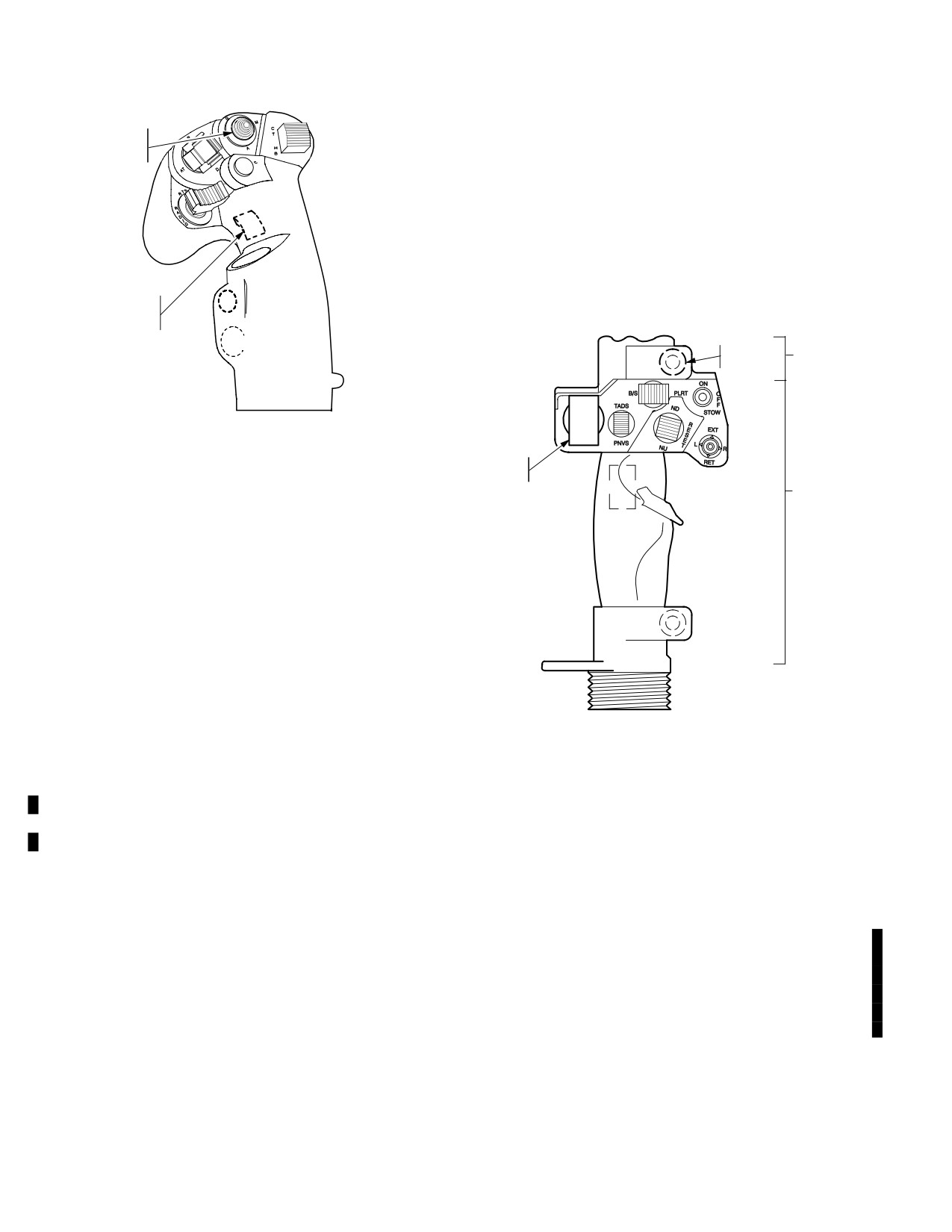
TM 1-1520-251-10
the first detent will fire a weapon if no inhibits exist. Press-
WEAPONS
ing the trigger to the second detent will override weapons
ACTION
SWITCH
performance inhibits and fire a weapon. Safety
constraints can never be overridden.
4.61 COLLECTIVE CONTROL
Weapon switches on the collective control grip (fig 4-72)
include the emergency stores jettison (JETT) switch on
the flight control grip and the missile advance (MSL ADV)
WEAPONS
switch on the mission control grip.
TRIGGER
SWITCH
MISSION
MISSILE
CONTROL
ADVANCE
GRIP
ÓÓÓ
LBA1039
ÓÓÓ
ÓÓÓ
Figure 4-71. Cyclic Control Grip
JETTISON
SWITCH
FLIGHT
CONTROL
GRIP
a. WAS Selections. WAS selections are as follows:
• G (Gun). Actions the AWS and slaves the gun to
the selected sight.
• M (Missile). Actions the Hellfire missile system;
allows the pylons to articulate and displays the
launch constraints symbol.
• A (Air-To-Air). Growth position; not active.
• R (Rocket). Actions the Rocket Management
LBA0759
Subsystem; allows the pylons to articulate and
displays the rocket steering symbol.
Figure 4-72. Collective Control Grips
b. WAS Logic. A weapon can be actioned from ei-
ther crewstation via the cyclic. Additionally, the CPG can
4.61.1 Missile Advance (MSL ADV) Switch. The MSL
action weapons via the LHG. The last crewmember to ac-
ADV switch is used to manually advance or select the
tion a weapon has control of that weapon. Exception: If
next missile in the firing sequence. When the Hellfire mis-
the CPG has rockets actioned via the ORT/TEDAC WAS
sile system is actioned in the manual mode, the MSL ADV
and the pilot actions rockets, cooperative moding is in ef-
switch on the collective mission grip is active. When the
fect. The active LOS will be the CPG’s LOS. The CPG’s
SAL missile mode is NORM or RIPL, the MSL ADV
rocket moding selections will be active in cooperative
switch is not active.
mode. The pilot’s type, quantity, and penetration selec-
tions will default to the CPG’s selections.
4.62 ORT/TEDAC HANDGRIPS
4.60.2 Weapons Trigger Switch. The weapons trigger
Armament system controls located on the ORT/TEDAC LHG
switch is a three position, two detent, guarded switch used
(fig 4-73) include the WAS and the weapons trigger switch.
to fire an actioned weapon. The switch is active when the
The MSL ADV switch is located on the ORT/TEDAC RHG.
A/S switch is in the ARM position. Pressing the trigger to
(fig 4-74)
Use or disclosure of this information is subject to the restriction(s) on the title page of this document.
4-82
Change 3
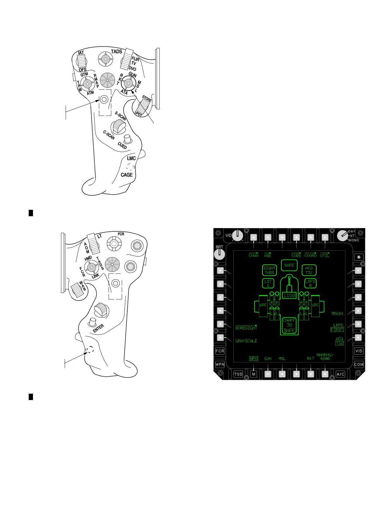
TM 1-1520-251-10
Z
• RKT (Rocket)
N
W
• ATA (Air to Air) (Inactive)
M
Functionally it is identical to the WAS located on the cyclic
control grip.
CURSOR
4.62.2
Weapons Trigger Switch. Functionally, this
weapons trigger switch is identical to the trigger switch lo-
L/R
WEAPONS
cated on the cyclic control grip.
TRIGGER
SWITCH
4.62.3 Missile Advance (MSL ADV) Switch. Func-
WEAPONS
ACTION
tionally, this MSL ADV switch is the same as the MSL
SWITCH
ADV switch located on the collective control grip.
4.63 WEAPONS (WPN) PAGE
The WPN page (fig 4-75) is used to functionally control
sight and weapons moding. Various sight and weapons
subsystem status windows, icons, and control selections
LBA1024
are included on the format to reduce workload and en-
hance situational awareness. Sight subsystem descrip-
tions are provided in Section I. The WPN page contains
Figure
4-73. LHG
the following weapons buttons:
Z
C−SCOPE
M
W
N
SLAVE
MAN TRK
ZOOM
HDD
ADV
MISSILE
ADVANCE
LBA2014
LBA0433A
Figure 4-74. RHG
Figure 4-75. WPN Page
4.62.1 Weapon Action Switch (WAS). The WAS is a
• T1
Missile CHAN button
5-position spring-loaded switch used to select a weapon
• T6
WPN UTIL button
for firing:
• B2
GUN button
• GUN (Gun)
• B3
MSL button
• MSL (Missile)
• B5
RKT button
Use or disclosure of this information is subject to the restriction(s) on the title page of this document.
Change 3
4-83
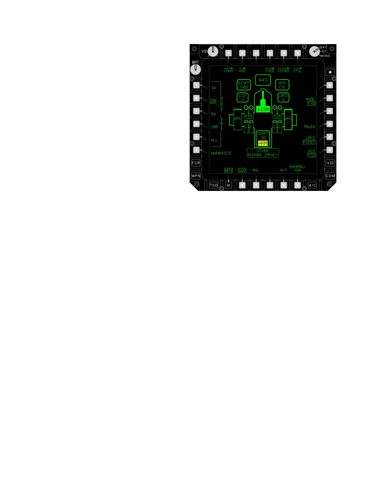
TM 1-1520-251-10
4.63.1
CHAN Button. The missile CHAN button is
used to access missile channels and stored laser codes
for missile channel coding.
4.63.2 WPN UTIL Button. The WPN UTIL button is
used to access weapons subsystem utility functions.
4.63.3 TRAIN Button. The TRAIN button is used to ac-
tivate and deactivate the weapon training mode (refer to
paragraph 4.74.7). The TRAIN button is displayed with a
barrier when armament control is in the ARM state or
when a weapon system is actioned in either crew station.
This button is not available when the Tactical Engagement
Simulation System (TESS) is enabled.
4.63.4 AKI Button. The AKI button is used to set the
Aircraft Kill Indicator (AKI) to off in order to avoid crew dis-
orientation when operating at night in heavy obscuration
(i.e., fog, dust, precipitation, etc.). It is displayed only
when operating in the TESS mode with an active kill, hit,
or near miss casualty indication (external AKI flashing
LBA1974A
light activated).
Figure 4-76. Gun System Controls
4.63.5 GUN Button. The GUN button is used to access
a. MODE Button. The gun MODE button is used to
gun system controls and system status. Selecting the
select operational mode of the gun system: NORM or
GUN button causes the gun icon to become inverse video
FXD. The NORM mode allows the gun to follow the se-
and calls up the gun controls around the edges of the dis-
lected sight while the FXD mode fixes the gun to the cent-
play (fig 4-76).
erline of the aircraft. Gun mode selections are indepen-
dent in each crew station.
b. BURST LIMIT Buttons. BURST LIMIT defines
the number of rounds to be fired with each trigger pull: 10,
20, 50, 100, or ALL. Burst limit selections will not exceed
turret control box burst limit selection.
c. HARMONIZE Button. The HARMONIZE button
is used to perform the gun system dynamic harmonization
procedure. This function is provided only in the CPG crew
station.
d. Gun Icon and Rounds Counter. The gun
rounds counter displays within the gun icon and will de-
crease in real time to reflect the number of rounds remain-
ing as the gun is fired. When all rounds have been fired,
the gun symbol displays zero.
Use or disclosure of this information is subject to the restriction(s) on the title page of this document.
4-84
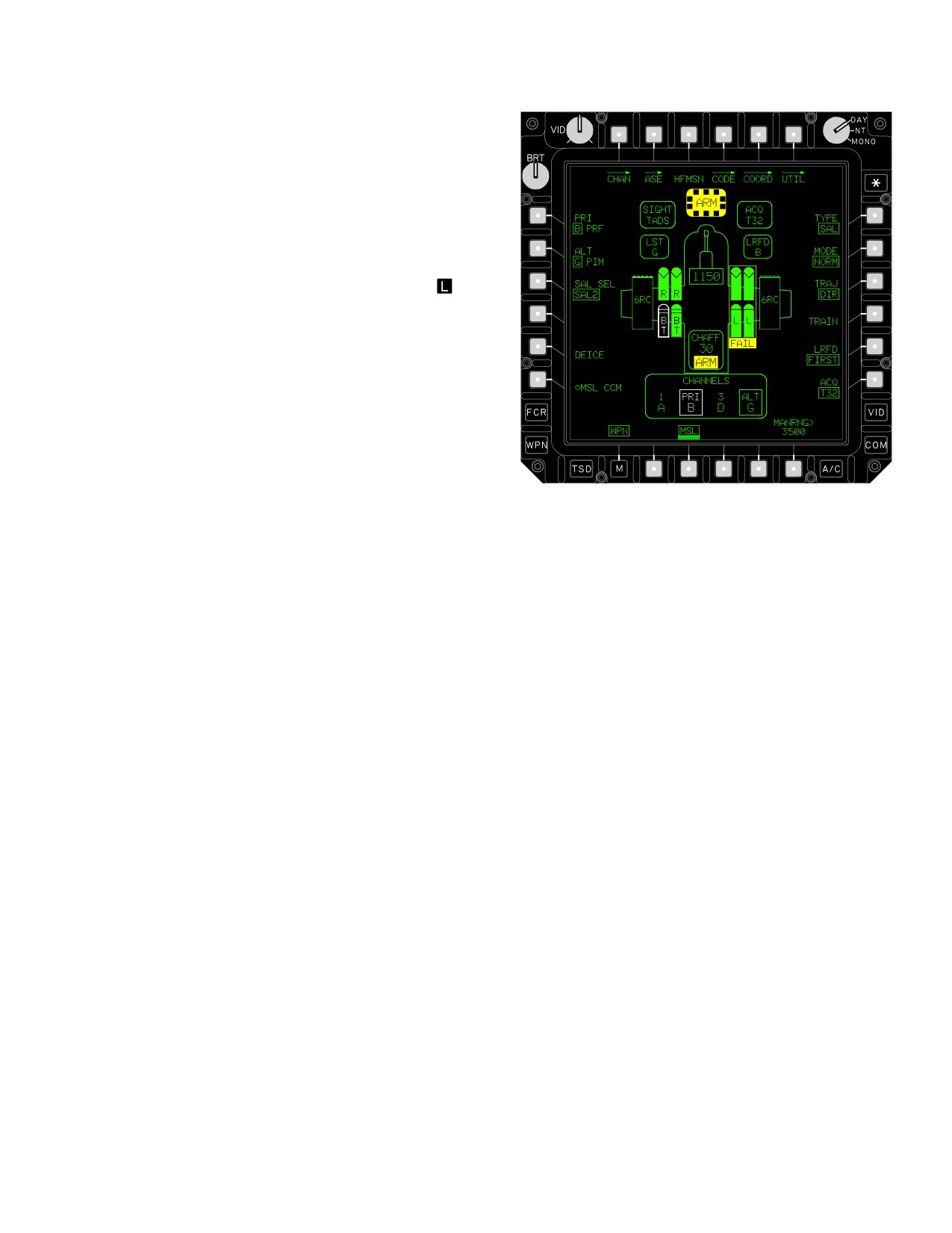
TM 1-1520-251-10
e. Gun FAIL Indicator. The gun FAIL indicator is
displayed in YELLOW within the gun icon when the gun
system is detected to be in a fail state. The FAIL status is
displayed in place of the rounds counter.
4.63.6 MSL Button. The MSL button is used to access
missile system controls and system status. Selecting the
MSL button causes all missile icons to become inverse
video and calls up missile controls around the edges of
the display (figs 4-77 and 4-80). If the sight is FCR
, the
display switches to an RF missile format even if there are
no RF missiles available. The page provides missile code
and status within the missile icons as described below.
LBA1975
Figure 4-77. SAL Missile System Controls
Use or disclosure of this information is subject to the restriction(s) on the title page of this document.
4-85
TM 1-1520-251-10
• L1
PRI button
e. MSL CCM Button. The MSL CCM button is used
to enable the counter-countermeasures within the SAL
• L2
ALT button
missile.
• L3
SAL SEL button
f. TYPE Button. The missile TYPE button is used
• L5
DEICE button
to set the desired missile type: SAL or RF. Missile TYPE
• L6
MSL CCM button
selections are independent in each crewstation.
• R1
TYPE button
g. MODE Button. The missile MODE button is used
to select the operational mode of the missile system in the
• R2
MODE button
SAL missile format: NORM, RIPL, and MAN. The NORM
• R3
TRAJ button
allows for firing missiles coded to the priority (PRI) chan-
nel. The RIPL mode allows for firing of missiles coded to
a. PRI Button. The PRI button is used to designate
both the priority channel and the alternate channel. The
the priority missile channel for coding SAL missiles. Prior-
MAN mode allows selection of a single missile for firing.
ity channel is common to both crewstations. Selecting the
SAL missile mode selections are common to both crew
PRI button will provide the channel options as set up on
stations.
the CHAN page. PRI button must be selected before se-
lecting ALT. A PIM (pulse interval modulation) or PRF
h. TRAJ Button. The TRAJ button is used to select
(pulse repetition frequency) label is displayed adjacent to
the desired missile launch trajectory: DIR, HI, or LO. DIR
the button label to indicate the type of laser code in the
is used when the aircraft has direct line of sight to the tar-
priority channel.
get. HI/LO are used when a high altitude trajectory is re-
quired. Trajectory mode selections are independent in
each crew station.
b. ALT Button. The ALT button is used to desig-
nate the alternate missile channel for coding SAL mis-
i. SAL Missile Status Window. The SAL missile
siles. Alternate channel is common to both crewstations.
status window in the lower center area of the format indi-
Selecting the ALT button will provide the channel options
cates the current status of missile channel coding and
as set up on the CHAN page. A PIM (pulse interval modu-
priority/alternate channel selections for all 4 SAL missile
lation) or PRF (pulse repetition frequency) label is dis-
channels. The priority channel label, laser code and box
played adjacent to the button label to indicate the type of
are displayed in WHITE.
laser code in the alternate channel.
j. SAL Missile Icons. When the missile system in-
ventory detects SAL missiles present on the launcher
c. SAL SEL Button. The SAL SEL button is used
rails, unique SAL missile icons (fig 4-78) display to reflect
to select the type of SAL missile when in the SAL missile
this condition. Missile type, status, and fault condition in-
format: AUTO, SAL1, and SAL2. For missile system op-
formation is displayed within the icon symbol. Icons may
erations Basic Hellfire missiles will be identified as SAL 1
be displayed in normal or inverse video depending on
missiles and Hellfire II missiles will be identified as SAL 2
whether the MSL button is selected or the missile system
missiles. SAL 1 missiles are only capable of PRF laser
is actioned. The icon will be displayed in WHITE and flash
code operation. SAL 2 missiles are capable of both PRF
between a bold and normal line when that missile is se-
and PIM laser code operations. The AUTO allows for au-
lected as the next missile to be launched in the firing se-
tomatic selection of a SAL 1 or SAL 2 missile. If the code
quence, regardless of these selections.
type is PRF the missile system will select SAL 2 missiles
first, if available, over SAL 1 missiles. If the code type is
k. RF Missile Icons. When the missile system in-
PIM the system will select only SAL 2. The SAL1 selection
ventory detects RF missiles present on the launcher rails,
allows for firing of only SAL 1 missiles. The SAL2 selec-
unique RF missile icons (fig 4-79) display to reflect this
tion allows for firing of only SAL 2 missiles.
condition. Missile type, status, and fault condition informa-
tion is displayed within the icon symbol. Icons may be dis-
d. DEICE Button. The missile DEICE button is
played in normal or inverse video depending on whether
used to manually de-ice SAL missile seekers in prepara-
the MSL button is selected or the missile system is ac-
tion for missile launch. The DEICE button (L5) is only
tioned. The icon will be displayed in WHITE, normal video
presented when the aircraft state is ARM and the missile
when that missile is selected as the next missile to be
system is actioned. Selecting the button causes the se-
launched in the firing sequence, regardless of these
lected missile seeker’s protective de-ice cover to jettison.
selections.
Use or disclosure of this information is subject to the restriction(s) on the title page of this document.
4-86
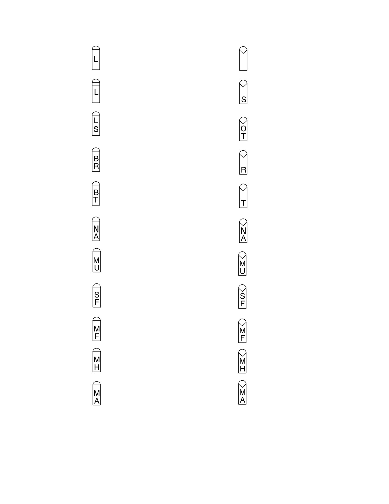
TM 1-1520-251-10
SAL 1
LASER MISSILE PRESENT
RF MISSILE PRESENT
RF MISSILE POWERED
SAL 2
LASER MISSILE PRESENT
BUT NOT YET ALIGNED
LASER MISSILE POWERED
BUT NOT YET CODED
RF MISSILE HAS BEEN DETECTED
IN AN OVER−TEMPERATURE
STATE
PRIORITY SAL MISSILE,
RF MISSILE READY
NEXT MISSILE LOAL
TO RECEIVE
TARGET
MISSILE SEEKER IN
MISSILE SEEKER IN
TRACK MODE
TRACK MODE
MISSILE HAS BEEN DETECTED
MISSILE HAS BEEN DETECTED
AS NOT AVAILABLE
AS NOT
AVAILABLE
MISSILE IS
ON
LAUNCHER
MISSILE IS UNLATCHED
ON LAUNCHER
MISSILE LAUNCHER
MISSILE LAUNCHER
HAS
FAILED
HASTION
FAILED
MISSILE HAS FAILED BIT
MISSILE HAS FAILED BIT OR
HAS BEEN DETECTED AS
HAS BEEN DETECTED AS
FAILED SUBSEQUENT TO
FAILED SUBSEQUENT TO
BIT
BIT
MISSILE HAS BEEN
MISSILE HAS BEEN REPORTED
AS
HANGFIRED
AS HANGFIRED
MISSILE LAUNCH SEQUENCE HAS
MISSILE LAUNCH SEQUENCE HAS
ABORTED OR MISSILE HAS MISFIRED
ABORTED OR MISSILE HAS MISFIRED
LBA2576
LBA2577
Figure 4-78. SAL Missile Icons and Status
Messages
Figure 4-79. RF Missile Icons and Status Messages
Use or disclosure of this information is subject to the restriction(s) on the title page of this document.
4-87
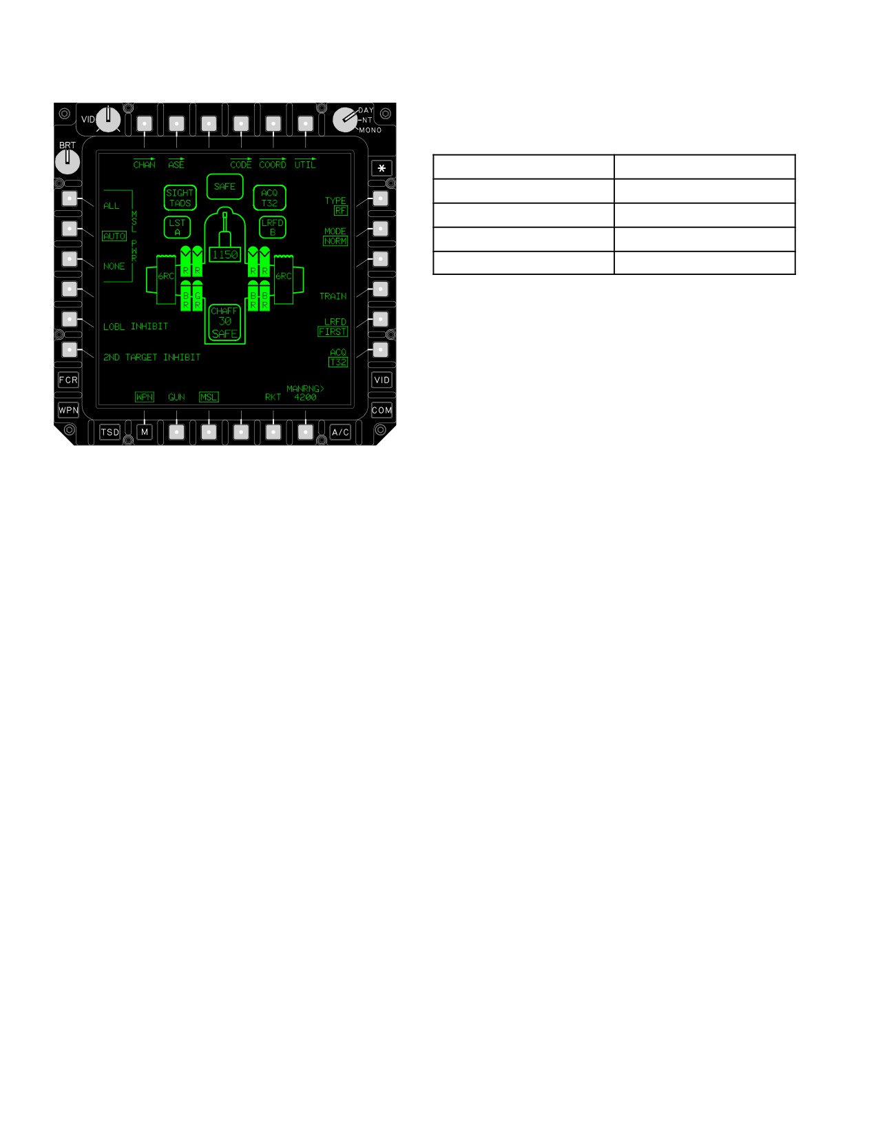
TM 1-1520-251-10
Table 4-22. MSL Available/MSL PWR
(AUTO MODE)
Missiles Available
Missiles Powered
8 or more
4
4-7
2
2-3
1
1
0*
* Unless missiles are actioned, then 1 is powered.
Selecting the NONE button removes power to all RF mis-
siles. When the RF missile MODE is MAN the MSL PWR
buttons are not displayed. MSL PWR selection is common
to both crew stations.
m. LOBL INHIBIT Button. The Lock On Before
Launch LOBL INHIBIT button inhibits the RF missile
LBA1976
seeker from transmitting and attempting to track the se-
lected target while on the rail during an RF engagement.
LOBL INHIBIT selection is common to both crew stations.
n.
2ND TARGET INHIBIT Button. The 2ND TAR-
GET INHIBIT button is used to prevent secondary target
information from being handed over from the FCR to the
primary RF missile during a stationary target engage-
Figure
4-80.
RF Missile System Controls
ment. 2ND TARGET INHIBIT is common to both crew sta-
tions.
o. MODE Button. The MODE button is used to de-
• L1 - L3
MSL PWR buttons
termine how control of power to the RF missiles will occur.
The MODE button toggles between NORM and MAN
• L5
LOBL INHIBIT button
modes and will power the RF missiles according to MSL
PWR selection. The MAN MODE allows the operator to
• L6
2ND TARGET INHIBIT button
use the Manual Advance (MAN ADV) switch to to select
and power a single RF missile for firing. It also allow the
• R2
MODE button
crew to manually advance through the RF missiles to se-
• R4
TRAIN button
lect a desired missile for power application. When the
MAN MODE is selected, the MSL PWR selection is re-
moved. RF missile MODE is common to both crew sta-
l. MSL PWR Buttons. MSL PWR buttons are used
tions.
to select the desired method of RF missile management:
ALL, AUTO, and NONE. Selecting the ALL button com-
p. Missile Launcher Rail Icons. Missile launcher
mands power to all RF missiles. Selecting the AUTO but-
rail icons (fig 4-81) indicate launcher present and missile
ton automatically manages power to the missiles to pre-
inventory status. Like the individual missiles icons, the
vent overheating. The number of missiles powered is
launcher rail icons become inverse video when selected
based on the total missile inventory (table 4-22) available.
or when the missile system is actioned.
Use or disclosure of this information is subject to the restriction(s) on the title page of this document.
4-88
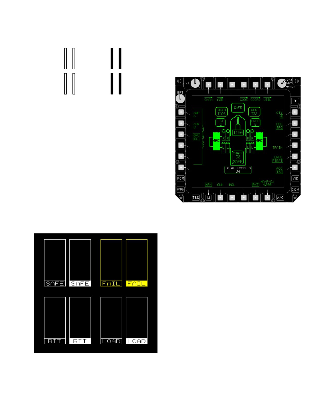
TM 1-1520-251-10
MISSILE LAUNCHER PRESENT
4.63.7 RKT Button. The RKT button is used to access
(FOUR RAIL SYMBOLS)
rocket system controls and system status. Selecting the
RKT button causes the rocket launcher icons to become
inverse video and calls up the rocket system controls
around the edges of the display (fig 4-83).
NORMAL
INVERSE
LBA0434
Figure 4-81. Missile Launcher Rail Icons
q. Missile Launcher FAIL/SAFE/BIT/LOAD
Icons. Unique missile launcher status icons (fig 4-82)
are displayed under certain conditions: the WHITE
launcher SAFE icon is displayed when the launcher
SAFE/ARM switch is in the SAFE position; the WHITE
launcher BIT icon is displayed when launcher IBIT is in
progress; the WHITE launcher LOAD icon is displayed
when the loading of keyword(s) to the launcher is in prog-
ress; the YELLOW FAIL icon is displayed when a fail
condition is detected that affects missile operation. These
LBA1977B
icons are displayed around the missile icons of the af-
fected launcher.
Figure 4-83. Aerial Rocket System Controls
• L1 - L5
INVENTORY Buttons
• R1
QTY button
• R2
PEN button
a. INVENTORY Buttons. The INVENTORY buttons
are used to select the desired rocket warhead and type to
be fired. Rocket INVENTORY type and warhead selec-
tions are independent in each crew station.
NORMAL
INVERSE
NORMAL
INVERSE
b. QTY Button. The QTY button is used to select
the desired number of rocket pairs to be fired with each
trigger pull: 1, 2, 4, 8, 12, 24, and ALL. When QTY is 1, a
single rocket will be fired with each trigger pull. For the re-
maining QTY options, rockets will be fired in pairs with
each trigger pull. Rocket Quantity selections are indepen-
dent in each crew station.
c. PEN Button. The PEN button is used to select
NORMAL
INVERSE
NORMAL
INVERSE
the desired warhead fuse penetration setting. The PEN
LBA0435
button displays when warheads which require a penetra-
tion selection, such as RC4 or 6RC (M433 fuze), are
loaded. Warhead penetration selections are independent
Figure 4-82. Missile Launcher Status Icons
in each crew station.
Use or disclosure of this information is subject to the restriction(s) on the title page of this document.
4-89
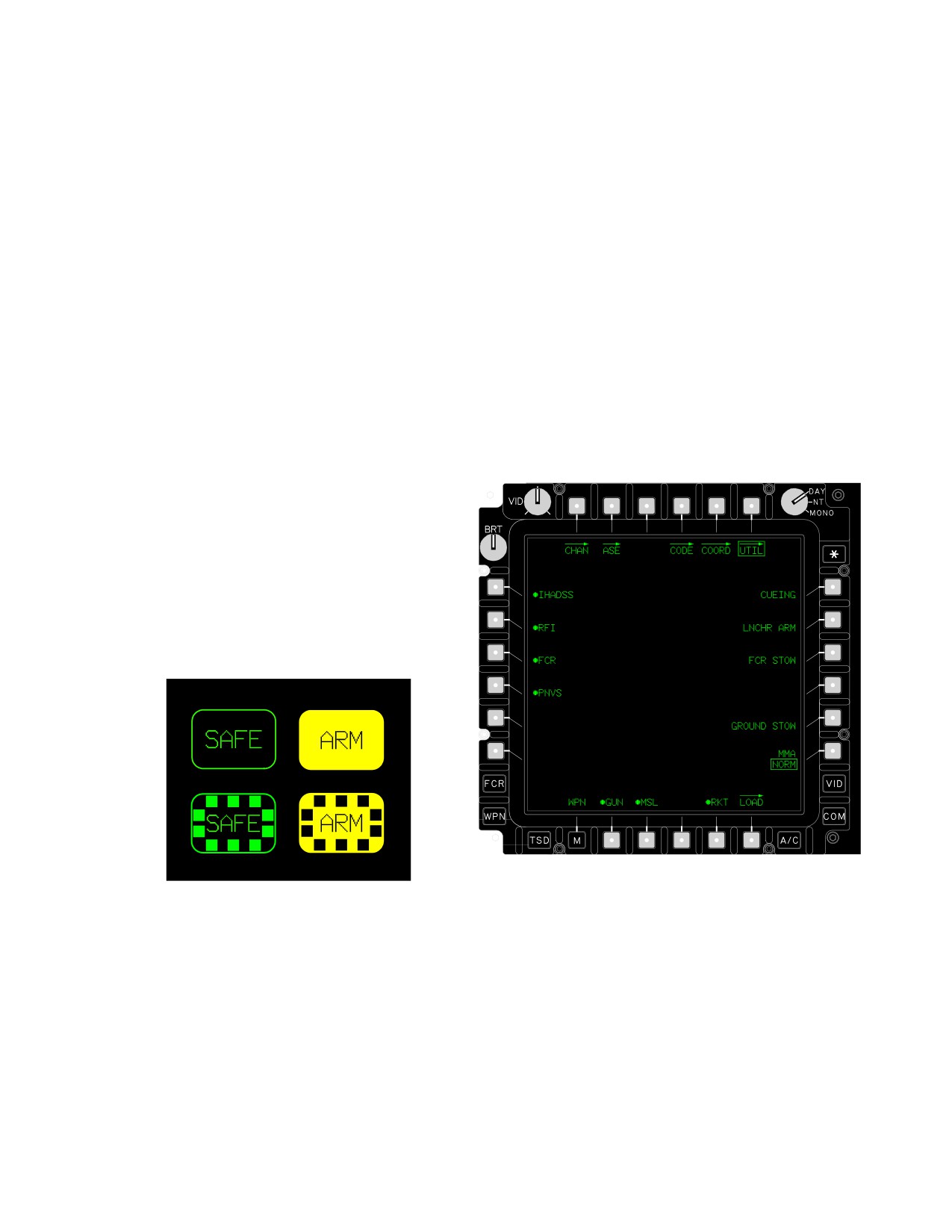
TM 1-1520-251-10
d. Total Rockets Status Window. The TOTAL
4.63.10 CHAFF Status. The CHAFF status displayed
ROCKETS status window in the inventory format area in-
in the center area of the WPN page provides the remain-
dicates the total rockets remaining for the type warhead
ing number of chaff cartridges decremented by the system
selected when the total and available quantities are not
processor and the current chaff dispenser status: SAFE or
equal. This status window is displayed in WHITE.
ARM. The dispenser status is displayed in GREEN when
the status is SAFE; it is displayed in YELLOW when the
e. Rocket Launcher Icons. Rocket launcher icons
status is ARM.
are displayed at the appropriate station. The inventory
type and warhead selected is presented within the launch-
4.64 WPN UTILITY (UTIL) PAGE
er icons.
The WPN UTIL page (Pilot) (fig 4-85) is used to enable
f. Rocket Launcher Degraded Icons. When the
weapon systems and provide access to the LOAD page.
rocket system has been detected as degraded, a YEL-
Although many utility functions may be premoded by use
LOW DEGR icon will be displayed around the rocket
of the Data Transfer Cartridge (DTC), this page provides
launcher icon.
access to utility functions while in flight. The CPG’s WPN
UTIL page (fig 4-85) provides the same functions. Sight
g. Rocket Launcher Fail Icons. When the rocket
subsystem control descriptions are provided in Section I.
system has been detected as failed, the station will be un-
available and a YELLOW FAIL icon will be displayed
around the rocket launcher icon.
4.63.8 ARM/SAFE Status Window. The ARM/SAFE
status window displayed in the upper area of the WPN
page provides the current aircraft status: SAFE or ARM. It
is displayed in GREEN when the status is SAFE; it is dis-
played in YELLOW when the status is ARM. Cross-hatch
symbol coding is added to the status window when a
weapon is actioned (fig 4-84). ARM/SAFE status is com-
mon to both crew stations.
WEAPON NOT
ACTIONED
(COMMON)
WEAPON
ACTIONED
(INDEPENDENT)
LBA2584
LBA1978
Figure 4-85. WPN UTIL Page (Pilot)
Figure 4-84. ARM/SAFE Status Window
• T6
WPN UTIL button
• R2
LNCHR ARM button
4.63.9 Weapon Actioned Format. When a weapon is
• R5
GROUND STOW button
actioned for firing, the respective weapon controls will be
• B2
GUN On/Off button
available as previously discussed, and all icons
associated with the actioned weapon will become inverse
• B3
MSL On/Off button
video. Weapon system buttons (GUN, RKT, MSL) are not
• B5
RKT On/Off button
available when a weapon has been actioned. WAS status
is independent in each crewstation.
• B6
LOAD button
Use or disclosure of this information is subject to the restriction(s) on the title page of this document.
4-90
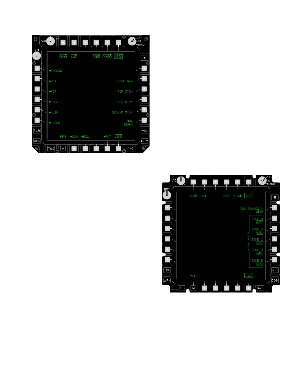
TM 1-1520-251-10
4.64.7 Casualty Status Window. The casualty status
window is displayed in the upper area of the format to pro-
vide the casualty indication status and the opposing
weapon type/identification code for the most recent en-
gagement event when operating in the TESS mode. This
status window is displayed only when a casualty status is
active (figure 4-95). The casualty “INDICATION” status
shall be one of three messages:
• “NEAR MISS”
• “HIT”
• “KILL”
The opposing “WPN IDCODE” shall be one of 37 two - dig-
it codes in a range from 00 to 36. The aircrew must refer to
the appropriate technical manual for the description of
these codes.
4.65 WEAPONS LOAD PAGE
The weapons LOAD page (fig 4-87) is used to access the
GUN ROUNDS and RKT INV zone buttons to manually
LBA0432
override the data loaded at the LMP or the DTC. The
weapons LOAD page provides the following button selec-
tions:
Figure
4-86.
WPN UTIL Page (CPG)
4.64.1 LNCHR ARM Button. The LNCHR ARM button
is used to arm the Hellfire missile launchers. Selecting this
button will command the Remote Launcher Safe/Arm
switch on all Hellfire missile launchers to the ARM posi-
tion.
4.64.2
GROUND STOW Button. The GROUND
STOW button is used to stow the wing pylons to achieve
optimum ground clearance.
4.64.3 GUN Button. The GUN button is used to en-
able/disable the gun system.
4.64.4 MSL Button. The MSL button is used to to en-
LBA1979
able/disable the missile system.
Figure 4-87. LOAD Page
• R1
GUN ROUNDS button
4.64.5 RKT Button. The RKT button is used to enable/
• R2 - R6 RKT INV ZONE buttons
disable the aerial rocket system.
4.65.1
GUN ROUNDS Button. The GUN ROUNDS
button is used to manually enter the number of rounds
4.64.6 LOAD Button. The LOAD button is used to ac-
loaded. This entry overrides the value entered at the LMP.
cess the controls required to manually override the data
The range value entry will be from 0 to 1200 rounds in 1
loaded at the maintenance load panel.
round increments.
Use or disclosure of this information is subject to the restriction(s) on the title page of this document.
4-91
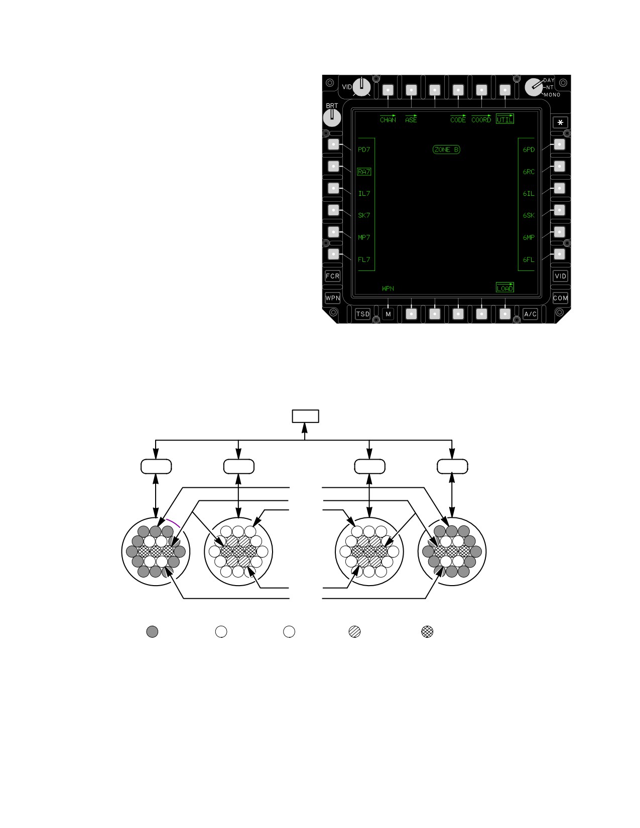
TM 1-1520-251-10
4.65.2 RKT INV Buttons. The RKT INV buttons
(fig 4-88) are used to select the desired rocket type and
warhead for a particular zone. Selecting one of these but-
tons calls up the RKT Launcher ZONE status window and
all inventory options:
• L1 PD7 button
• L2 RA7 button
• L3 IL7 button
• L4 SK7 button
• L5 MP7 button
• L6 FL7 button
• R1 6PD button
• R2 6RC button
• R3 6IL button
LBA2038
• R4 6SK button
Figure 4-88. RKT INV Page
• R5 6MP button
4.65.3 RKT Zone Inventory. Rocket Zone Inventory is
• R6 6FL button
displayed in figure 4-89.
WP
PIU
PIU
PIU
PIU
ZONE A
ZONE E
ZONE C
LEFT
ÓÓÓ
ÓÓ
RIGHT
OUTBOARD
OUTBOARD
LAUNCHER
ÓÓÓ
ÓÓ
LAUNCHER
ÓÓÓ
ÓÓ
ZONE D
ZONE B
LEFT INBOARD
RIGHT INBOARD
LAUNCHER
LAUNCHER
Ó
ZONE A
ZONE B
ZONE C
ZONE D
ZONE E
LBA2594
ÓÓ
Figure 4-89. Rocket Zone Inventory
Use or disclosure of this information is subject to the restriction(s) on the title page of this document.
4-92
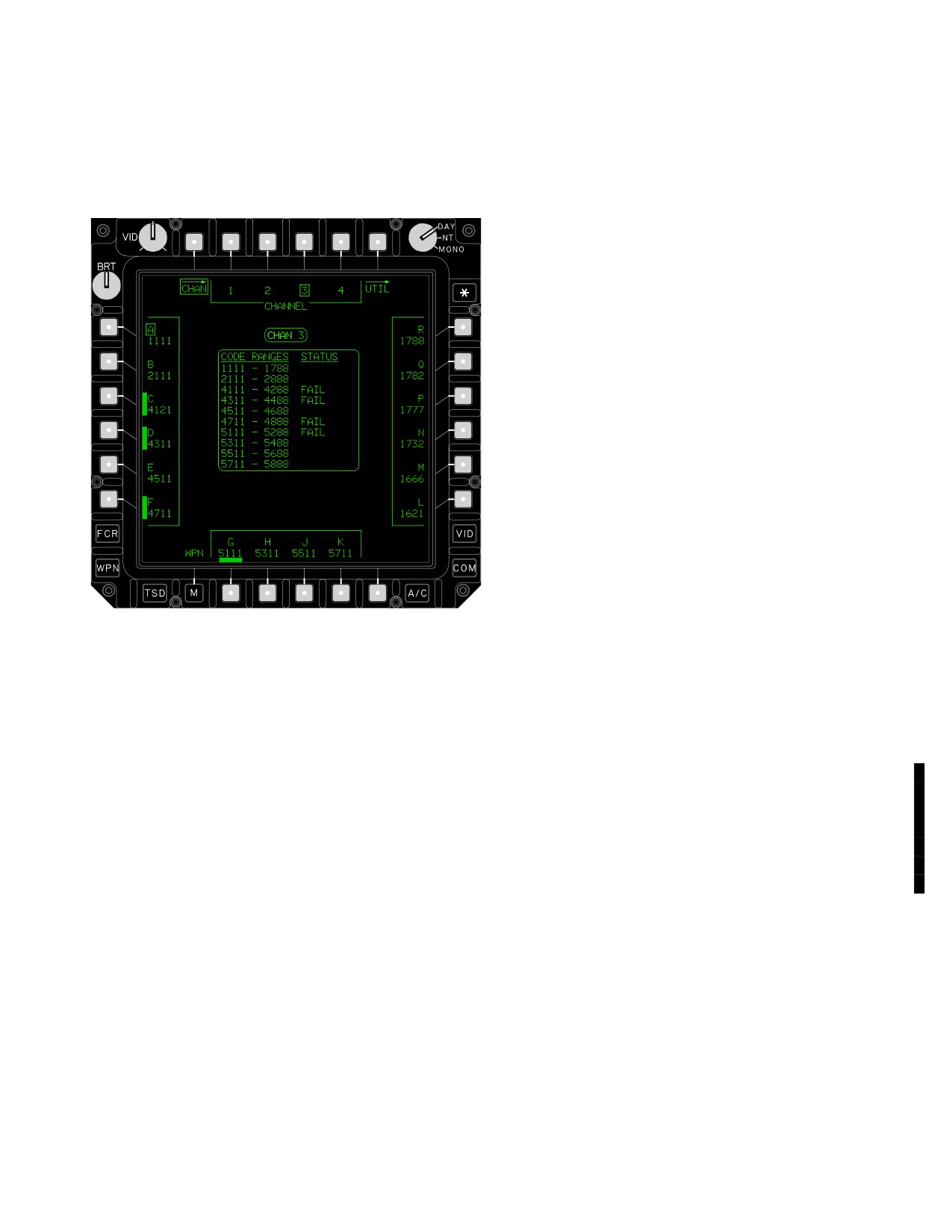
TM 1-1520-251-10
4.66 MISSILE CHANNEL (CHAN) PAGE
4.66.2 CHAN Code Buttons. The missile CHAN Code
buttons are used to select the code for the current missile
The missile CHAN page (fig
4-90) is used to select the
channel as indicated by the selected CHANNEL option
laser codes to be loaded into the four missile channels.
button. A missile CHAN code button will be displayed with
a barrier when that code is not available.
4.66.3
Code Range and Keyword Status Win-
dow.
The information displayed in this status window is
described in paragraph 4.9.5.
4.67 AREA WEAPON SYSTEM (AWS) DESCRIPTION
The AWS consists of the M230E1 30mm Automatic Gun,
Gun Control Box, Gun Turret, Turret Control Box, and am-
munition handling system.
4.67.1 M230E1 30mm Automatic Gun. The M230E1
is an externally powered, chain driven weapon mounted in
a hydraulically driven turret which is mounted on the un-
derside of the helicopter forward fuselage. Gun major
components are: receiver assembly, index drive assem-
bly, bolt carrier assembly, forward track assembly, recoil
mechanisms, drive motor, flash suppressor, and barrel. It
incorporates positive cook-off safety (open bolt) and
double ram prevention. The rate of fire is 625 ±25 rounds
per minute. The gun turret is capable of azimuth move-
ment of 86° left or right of the helicopter centerline, +11°
LBA1980
elevation (+9° elevation within ±10° of centerline), and
- 60° depression.
Figure
4-90.
CHAN Page
4.67.2 Ammunition Handling System. The ammuni-
tion handling system receives and stores 30mm linkless
The CHAN page provides the following button selections:
ammunition and delivers the rounds through fixed and
flexible feed chutes to the 30mm gun on demand. The am-
• T2 - T5
CHANNEL buttons
munition handling systems maximum capacity is 1200
rounds. The amount of rounds will be reduced with the
• L1 - L6
CHAN Code buttons
installation of the IAFS. The quantity will be approximately
• R1 - R6 CHAN Code buttons
94 rounds, with the 130 gal fuel cell, if utilizing the upload-
• B2 - B5
CHAN Code buttons
er/downloader or approximately 58 rounds using the side-
loader. The 100 gal fuel cell includes a 242 round am-
4.66.1
CHANNEL Buttons. The missile CHANNEL
munition storage magazine, making the maximum
buttons are used to code SAL missile channels 1 through
capacity about 300 rounds. The system can accommo-
4 using CHANNEL option buttons. Selecting the desired
date a variety of 30mm ammunition including high explo-
channel determines to which missile channel subsequent
sive dual purpose (HEDP M789), ADEN/DEFA, HEI
CHAN Code selections apply.
(M799), and TP (M788).
Use or disclosure of this information is subject to the restriction(s) on the title page of this document.
Change 2
4-93
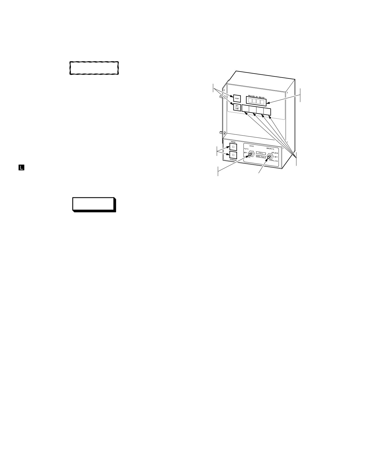
TM 1-1520-251-10
4.68 AWS SYSTEM OPERATION
The S/MC provides the discrete interface link between the
Turret Control Box, Carrier Drive, LH and RH tensioners,
GSE Loader, Loader Assembly, and Weapons Processor.
CAUTION
The AWS will continue to follow IHADSS
LIGHTING
LOS when operating in NVS FIXED mode.
FUNCTION
ROUNDS
COUNT
DISPLAY
NOTE
In the event of power loss, the gun is spring
driven to +11° elevation to prevent dig-in
during landing.
LOADER
The AWS can be directed by either crewmember in the
SWITCHING
ENTERING
NORM mode when the active sight is HMD, TADS or FCR
ROUNDS
COUNT
. The system can also be employed in the FIXED (+6° in
MODE
elevation) mode which aligns the gun forward in azimuth to
SWITCHING
OPERATE
the helicopter centerline. The software limit is 4200 meters.
SWITCHING
LBA2588
Figure 4-91. Sideloader/Magazine Controller
WARNING
The S/MC operational interface can be grouped into five
Failure to adhere to the published gun
functional areas:
duty cycle may result in a catastrophic
failure, loss of aircraft, injury or death.
a. Lighting functions. When powered, the S/MC
sets display lighting to the maximum night time intensity.
Successive button pushes of the NIGHT button will se-
The gun duty cycle is as follows:
quentially cycle the intensity to the minimum night time in-
• Six 50 round bursts with 5 seconds between bursts
tensity in five steps, and then back to the maximum inten-
followed by a 10 minute cooling period.
sity on the sixth button press. A momentary press of the
DAY/TEST button provides maximum display lighting in-
• For BURST LIMITER settings other than 50, the
tensity for readability under direct sun light. Pressing the
cycle can be generalized as no more than 300
NIGHT button after selecting DAY lighting will return the
rounds fired within 60 seconds before allowing the
display intensity to the maximum night time intensity.
gun to cool for 10 minutes, after which the cycle
Pressing and holding the DAY/TEST button for longer
may be repeated.
than 3 seconds will initiate a lamp test routine which illumi-
nates all display segments, legend lamps, and indicators
to confirm that all lighting circuits are functional. When the
4.68.1 Sideloader/Magazine Controller (S/MC). The
squat switch status indicates that the aircraft is airborne,
S/MC (fig 4-91) is an LRU with control features provided
the S/MC disables the display indicators to extend service
for direct operator interface during loading operations.
life.
The S/MC is mounted in the RH FWD Avionics Bay adja-
cent to the Loader Assembly for one-man operation.
b. Rounds Count Management. Four momentary
push button switches are used for manually editing the
The S/MC performs three distinct ammunition handling
displayed numeric value of rounds count which is stored in
system functions:
the S/MC non-volatile memory. This data is not down-
loaded to the aircraft and must be loaded via the LMP or
• counting of 30mm rounds
LOAD page.
• control of the Carrier Drive Assembly
c. Loader Switching. This function is provided by
• control the Loader Assembly for uploading and
two momentary push buttons labeled ENGAGE and DIS-
downloading 30mm ammunition
ENGAGE. These push buttons provide for the automatic
Use or disclosure of this information is subject to the restriction(s) on the title page of this document.
4-94