HELICOPTER, ATTACK, AH-64D LONGBOW APACHE. TECHNICAL MANUAL (2002) - page 8
TM 1-1520-251-10
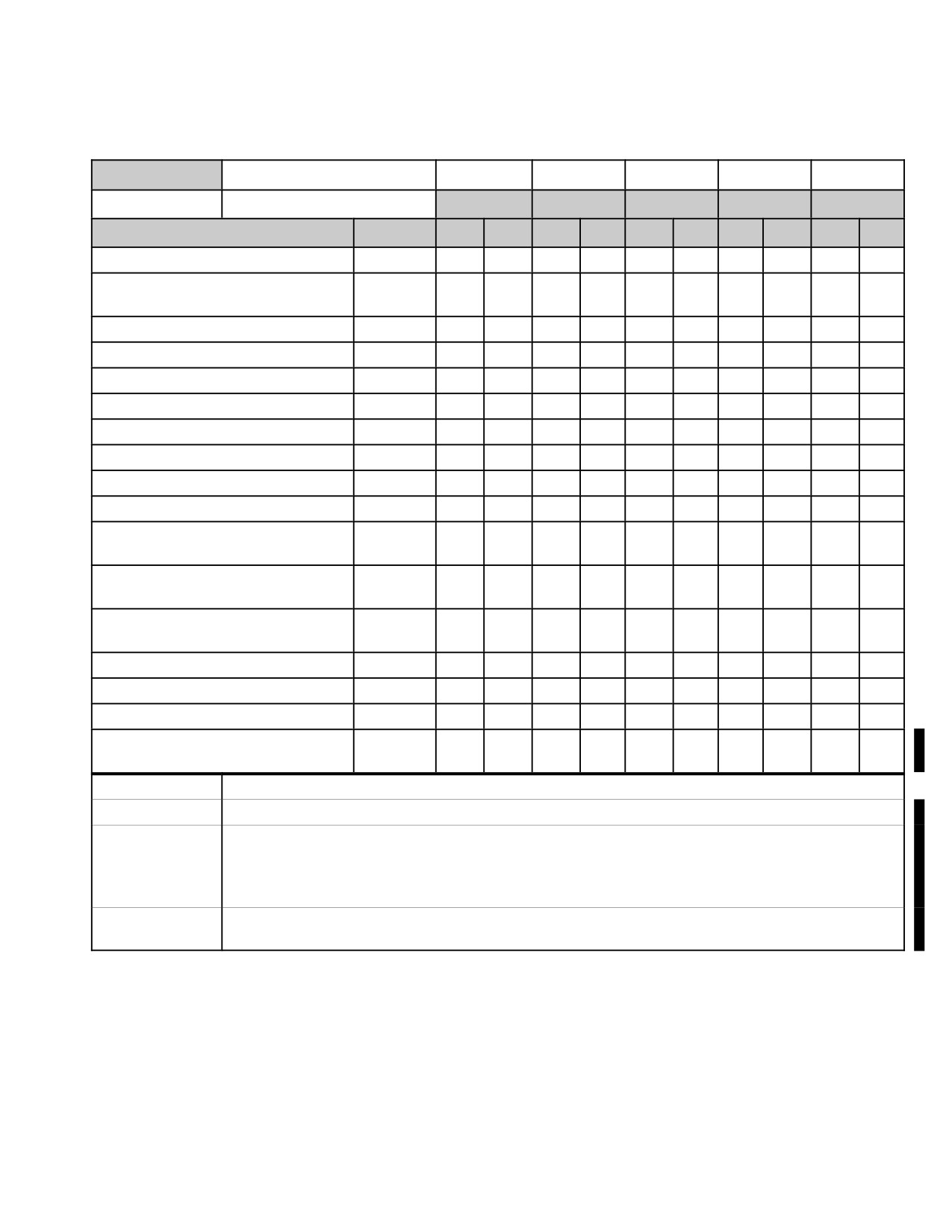
Table 3A-4. Messages - continued
RADIO
Message Format
AFAPD
ATHS
JVMF
JVMF
N/A
Protocols
LONGBOW
TACFIRE
TI
FS
HF
MESSAGE
TSD REC
TX
REC
TX
REC
TX
REC
TX
REC
TX
REC
AIR FIRE MISSION - EOM
X
X
X
OBSERVER READINIESS
X
REPORT
AIR FIRE MISSION - ACPT/REJT
X
X
AIR FIRE MISSION - READY
X
X
AIR FIRE MISSION - SHOT
X
X
CALL FOR FIRE
X
ON - CALL FIRE COMMAND
X
MESSAGE TO OBSERVER
X
X*2
X
OBSERVER MISSION UPDATE
X
X*2
X
CHECK FIRE - ALL or MISSION
X
CANCEL CHECK FIRE - ALL or
X
MISSION
ADJUST FIRE - REPEAT/RNDS
X
IMPACT
END OF MISSION AND
X
SURVEILLANCE
FRAGO (FIELD ORDERS)
X
X
INFORMATION REQUEST
X
X
SA DATA (Sent automatically)
X
ATHS MESSAGES
X
X*3
X*3,
4
NOTE 1
Cannot perform auto - response in JVMF, but can issue report.
NOTE 2
This is a technical capability that does not reflect the normal operational use of this message.
NOTE 3
Reviewing an ATHS MSG from the COM MSG RCV page will call the ATHS message receive
page to display. The sending and receiving of all ATHS/TACFIRE messages can only be
achieved through the ATHS page structure and not the TSD or MSG SEND/MSG RCV pages.
Refer to table 3A-4E for ATHS/TACFIRE message types that are supported by the IDM.
NOTE 4
ATHS messages are not uniquely defined for TSD REC function and a standard ATHS MSG
descriptor is used to annunciate the receipt of an ATHS (TACFIRE) message.
Use or disclosure of this information is subject to the restriction(s) on the title page of this document.
Change 3
3A-81
TM 1-1520-251-10
Table
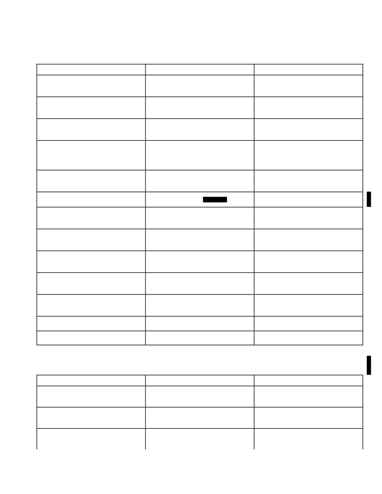
3A-4A. To transmit LONGBOW Messages
TYPE OF MESSAGE
MPD SELECTIONS/ACTIONS
TO SEND MESSAGE
RF Target Handover
After FCR scan, on FCR display
Select PRI member, then SEND
select NTS. Select RFHO
FCR Targets - All
TSD RPT TGT ALL
Select PRI member, then SEND
FCR Targets - Priority
TSD RPT TGT PRI
Select PRI member, then SEND
FCR Targets - Single or Multiple
TSD RPT TGT Cursor select single
Select PRI member, then SEND
or multiple FCR target icons
Shot At - All
TSD RPT BDA ALL
Select PRI member, then SEND
Shot At - Ownship
TSD RPT BDA OWN
Select PRI member, then SEND
Mode MSG to SEND
Shot At - Query
TSD RPT BDA OWN
Select PRI member, then SEND
Mode MSG to RQST
Pres Posn Report
TSD RPT PP
Select PRI member, then SEND
Mode MSG to SEND
Pres Posn Query
TSD RPT PP
Select PRI member, then SEND
Mode MSG to RQST
FARM Report
TSD RPT FARM
Select PRI member, then SEND
Mode MSG to SEND
FARM Query
TSD RPT FARM
Select PRI member, then SEND
Mode MSG to RQST
Single Stored Target/Threat
TSD POINT XMIT
Select PRI member, then SEND
Use cursor to select or point data
entry method to select target or
threat
Single Waypoint/Hazard
TSD POINT XMIT
Select PRI member, then SEND
Use cursor to select or point data
entry method to select
waypoint/hazard
Single Control Measure
TSD POINT XMIT
Select PRI member, then SEND
Use cursor to select or point data
entry method to select control
measure
Zones - Priority Fire
TSD BAM PF
Select PRI member, then SEND
Zones - No Fire
TSD BAM NF
Select PRI member, then SEND
Zones - All
TSD BAM BOTH
Select PRI member, then SEND
Use or disclosure of this information is subject to the restriction(s) on the title page of this document.
3A-82
Change 3
TM 1-1520-251-10
Table
3A-4A. To transmit LONGBOW Messages - continued
TYPE OF MESSAGE
MPD SELECTIONS/ACTIONS
TO SEND MESSAGE
Freetext
COM MSG SEND FREETEXT
SEND
SOURCE IDM Enter freetext
Waypoints file
COM MSG SEND CURRENT
SEND
MISSION WAYPOINTS
Routes file
COM MSG SEND CURRENT
SEND
MISSION ROUTE ALL
Single route
COM MSG SEND CURRENT
SEND
MISSION ROUTE, Select desired
Route
Laser codes
COM MSG SEND CURRENT
SEND
MISSION LASER CODES
Comm Data All
Not implemented in
BLK 2
Control Measures file
COM MSG SEND CURR MISSION
SEND
CONTROL MEASURES
Boundary/Phase Lines file
COM MSG SEND CURR MISSION
SEND
LINES
Engagement Areas file
COM MSG SEND CURR MISSION
SEND
AREAS
Stored Targets/Threats file
COM MSG SEND CURR MISSION
SEND
TGT/THRT
Current Mission - All
COM MSG SEND CURR MISSION
SEND
ALL
MISSION 1 - All files
COM MSG SEND MISSION 1
SEND
MISSION 2 - All files
COM MSG SEND MISSION 2
SEND
Table
3A-4B.
To Transmit JVMF messages over the Tactical Internet*
TYPE OF MESSAGE
MPD SELECTIONS/ACTIONS
TO SEND MESSAGE
Freetext
COM MSG SEND FREETEXT
SEND
SOURCE IDM Enter freetext
Information Request
TSD RPT PP
Select primary member, then SEND
Mode MSG to RQST
Present Position Report
TSD RPT PP
Select primary member, then SEND
Mode MSG to SEND
Use or disclosure of this information is subject to the restriction(s) on the title page of this document.
Change 3
3A-83
TM 1-1520-251-10
Table 3A-4B. To Transmit JVMF messages over the Tactical Internet* - continued
TYPE OF MESSAGE
MPD SELECTIONS/ACTIONS
TO SEND MESSAGE
Spot Report
TSD RPT SPOT
Select primary member, then SEND
Modify options as required
*These messages can also be sent via
the Fire Support net
Table 3A-4C. To Transmit JVMF messages over the Fire Support Net*
TYPE OF MESSAGE
MPD SELECTIONS/ACTIONS
TO SEND MESSAGE
Call for Fire
TSD RPT ARTY MSG CFF
Verify primary member selected, then
SEND
Default to NTS or cursor select
target/threat. Modify options as re-
quired
Cancel Check Fire - All
TSD RPT ARTY MSG CANC CHK
Verify primary member selected, then
Select CMD to ALL
SEND
Cancel Check Fire - Single Mission
TSD RPT ARTY MSG CANC CHK
Verify primary member selected, then
Select CMD to RESUME or EOM
SEND
Check Fire - All
TSD RPT ARTY MSG CHK FIRE
Verify primary member selected, then
Select TARGET to ALL
SEND
Check Fire - Single Mission
TSD RPT ARTY MSG CHK FIRE
Verify primary member selected, then
Select TARGET to SINGLE
SEND
End of Mission
TSD RPT ARTY MSG EOM
Verify primary member selected, then
SEND
End of Mission/Surveillance
TSD RPT ARTY MSG EOM/SURV
Verify primary member selected, then
SEND
Modify options as required
Observer Readiness Report
TSD RPT ARTY MSG OBS RDY
Verify primary member selected, then
SEND
On Call Request
TSD RPT ARTY MSG CFF
Verify primary member selected, then
SEND
* These messages cannot be transmitted via the Tactical Internet. Conversely, all JVMF messages that can be
transmitted via the Tactical Internet can be sent via the Fire Support net as well.
Use or disclosure of this information is subject to the restriction(s) on the title page of this document.
3A-84
Change 3
TM 1-1520-251-10
Table 3A-4D. To Transmit HF messages (SOURCE HF)
TYPE OF MESSAGE
MPD SELECTIONS/ACTIONS
TO SEND MESSAGE
Freetext
COM MSG SEND FREETEXT
SEND
SOURCE HF Enter freetext
Present Position (PP)
COM MSG SEND - SOURCE HF
SEND
PP Select
Pre Program Text (1 of 25)
COM MSG SEND - SOURCE HF
SEND
Select Pre Programmed Text Msg
3A.67 through 3A.70 Deleted.
• The artillery’s more recent 220B JVMF
protocol (equivalent to the AH - 64D FIRE
3A.71 ATHS - TACFIRE IMPROVED DATA MODEM
SUPPORT JVMF protocol) is the succes-
3A.71.1 ATHS-TACFIRE Mission Capabilities. Tacti-
sor to TACFIRE and is commonly, but not
cal Fire (TACFIRE) is a legacy battlefield communication
exclusively, the message protocol that is
tool that manages complex messages such as aerial and
used to request and control artillery fire
artillery fire requests, reports, emergency broadcasts, au-
with BLK2 AH - 64D.
tomatic reporting of status, movement commands, and
The 2.9I TACFIRE is designed to maintain current mission
general free text messages.
status for up to eight active airborne fire missions, two active
The primary function of TACFIRE is to coordinate firepow-
artillery fire missions, and two preplanned artillery fire mis-
er and communications with both legacy artillery systems
sions. The IDM retains all TACFIRE mission essential data in
and legacy OH-58D. The AH-64D type 304 IDM and
nonvolatile storage and will store 12-48 (1-4 TACFIRE ra-
avionics system supports the transmission and reception
dios) previously received TACFIRE messages. The system
of 2.9I TACFIRE messages, which are compatible with the
also supports the shooter/designator execution of a digital re-
Advanced Field Artillery Tactical Data System (AFATDS -
mote HELLFIRE mission and other airborne fire missions
when set to TACFIRE protocol), TACFIRE computer, For-
specifying rockets, gun, or HELLFIRE direct. The ATHS-
ward Entry Device (FED), and handheld Digital Messages
TACFIRE supports digital artillery fire missions as the For-
Device (DMD).
ward Artillery Aerial Observer (FAAO) and transmits/receives
spot situation reports, battle damage assessments, and
Like all the other IDM protocol messages, the crew station
casualty reports. Legacy aircraft team situational awareness
TACFIRE message receipt notification is provided
capabilities are enhanced by the ability to track team member
through the UFD (with tone) and the message receive
Fuel, Ammo, Rockets, and Missile (FARM) status along with
page.
the ability to track the present position of up to 15 team mem-
NOTE
bers per query.
• The AFATDS is the successor of the
TACFIRE computer. AFATDS is back-
ward compatible with the legacy TAC-
FIRE computer and the IDM ATHS - TAC-
FIRE (TACFIRE mode) message format.
Use or disclosure of this information is subject to the restriction(s) on the title page of this document.
Change 3
3A-85
TM 1-1520-251-10
3A.71.2 Physical Description and Implementa-
3A.71.3
ATHS - TACFIRE Initialization.
tion. The IDM is composed of a single Line Replaceable
Unit (LRU) that receives pertinent data over the 1553B
NOTE
bus from the DMS, EGI, SP, WP, onboard sensors, MPD,
Keyboard Unit (KU), and through the receipt of processed
• The aircraft’s ATHS - TACFIRE Net man-
TACFIRE messages. The TACFIRE pages are controlled
agement functionality is set, edited, and
by each independent crew station. When the ATHS page
controlled by the operator using the
button is selected from either crew station, the processed
ORIG ID page, NET page, and MODEM
TACFIRE format will be displayed on the MPD that re-
page.
quested the page. Following aircraft power - up, the initial
TACFIRE format in both crew stations will always be the
• The ATHS (TACFIRE) page should only
TACFIRE INDEX page. However, once the TACFIRE for-
be accessed for the purpose of sending
mat is changed in a specific crew station, the last dis-
and receiving TACFIRE messages or as
played format will always be displayed in that crew station
follows: 1) when operating with legacy
upon the next ATHS page button selection.
TACFIRE - only aircraft to check their SI-
TREP subscriber aircraft/weapons status
data; 2) when conducting single aircraft
The type 304 IDM is configured with Operational Flight
training and a different/net radio needs to
Program (OFP) software package Version 2, Revision 5
be set for receiving messages sent from/
(also referred to as 2.9I). This package consists of the
to the ownship; and 3) possible maintain-
Army User Interface (AUI) Computer Software Configura-
er requirements to view the IDM IP ad-
tion Item (CSCI) Version 2.9I and Modem CSCI Version
dress for loading purposes and to view a
R3.42. Together, they are identified by the Computer
detailed IDM listing of the various soft-
Program
Identification
Number
(CPIN):
ware and firmware module versions on
MD - 1295/A - 01A01 - U - V2.00(OFP.R5).
START (R2), RESET DATA> (R3), <SW -
VERS (L4) 1 / 4 pages.
In respect to the AH - 64D crew station implementation,
• Editing from the ATHS
(TACFIRE)
the terms Automatic Target Handover System (ATHS) and
START NET page (e.g., adding/removing
TACFIRE are used interchangeably. The ATHS page is
subscribers/members) will cause a data
accessed, for the purpose of sending or receiving TAC-
mismatch to occur between the aircraft
FIRE messages, by selecting the ATHS page button from
displays and the IDM which will invoke
the MSG REC page, MSG SEND page, RPT page, or by
the CLEAR button to display on the asso-
selecting the MSG RCV page’s RVW button when an
ciated COM page TACFIRE preset - net.
ATHS message is selected.
A subsequent selection of the CLEAR
button will send the DP data to the IDM,
The TACFIRE protocol incorporates two modes of opera-
overwriting any existing data for that pre-
tion: 1) AIR NET mode; and 2) TACFIRE (TFR) NET
set in the IDM.
mode. Both the AIR and TACFIRE modes are set anytime
• Following an aircraft startup, the initial
that a MODEM page BAUDRATE associated with the de-
sired mode is selected e.g., TACFIRE 1200 or AIR 1200.
displayed ATHS - TACFIRE format will al-
If a TACFIRE NET is to be used exclusively between IDM
ways be the INDEX page. After off - pag-
equipped aircraft, then AIR (default) NET mode should be
ing from an ATHS page format, the next
used. When communications will be established with the
selection of the ATHS page button will
artillery, legacy ATHS, or handheld DMD, then the TFR
display the last ATHS-TACFIRE page
NET mode should be selected. Differences in message
format that had previously been dis-
format and capabilities between the AIR and TFR modes
played in that crew station. Regardless of
exist.
what specific ATHS page is currently dis-
played, selecting the INDEX button will
command the INDEX page (top level
TACFIRE messages may be transmitted to and from other
ATHS page) to display.
TACFIRE capable aircraft, artillery TACFIRE/FIST ground
systems systems, DMD, and SINCGARS configured Por-
• A complete and detailed description of
table Flight Planning System - Army (PFPS - A) computer
the TACFIRE subsystem is described in
or AMPS computer.
Technical Bulletin 11 - 5895 - 1632 - 10.
Use or disclosure of this information is subject to the restriction(s) on the title page of this document.
3A-86
Change 3
TM 1-1520-251-10
The IDM TACFIRE page format was designed to support
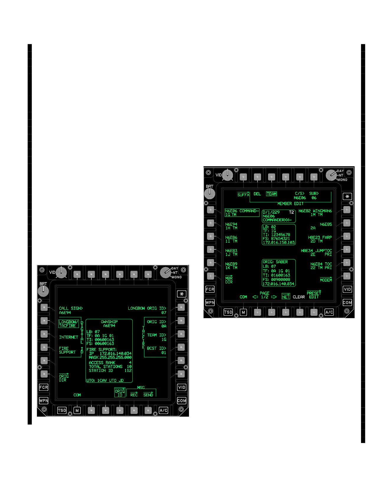
c. NET Page. Editing of a TACFIRE preset - net
any IDM aircraft inclusive of legacy non - 1553 bused and
members/subscribers or other data is accomplished
non - integrated aircraft. This means that the TACFIRE for-
through the COM Preset - Selected NET page and associ-
mat includes a number of pages that are not used by the
ated MODEM page. Data editing performed from the air-
AH - 64D crew member. This is particularly true with the
craft NET page will update the IDM; however, data editing
START pages. All TACFIRE NET management/editing
from the IDM (ATHS START NET page) will not usually
should be accomplished through the normal AH-64D
update the aircraft display. Refer to figure 3A-30 for all the
page and interfaces used for all the other IDM protocols.
button descriptions of the NET page.
a. DTU load and Manual Initialization. A TAC-
To enable the message send capability to any of a TAC-
FIRE preset - net is either initialized automatically through
FIRE preset - net members, they must first be assigned as
a DTU load or manually, through the same common
TM members, otherwise the IDM will not acknowledge
pages that are used with all the other IDM protocols; OR-
their presence and will not permit the entry of their sub-
IG ID page (fig 3A-86), COM preset NET page (fig 3A-87),
scriber/member ID for sending messages.
and NET MODEM page (fig 3A-88). An automatic initiali-
zation is contingent on a TACFIRE preset-net having
been constructed on the PFPS - A/AMPS and downloaded
to the DTC.
b. ORIG ID Page. Editing of the TACFIRE origina-
tor/ownship ID is accomplished from the ORIG ID page
and not from the ATHS (TACFIRE) START page. To setup
TM and BC ID, any one of the aircraft’s 8 preset - nets pro-
tocol has to be set as TACFIRE, has to contain the TM and
BC ID (just as a member), and TM and BC ID members
have to be set with an active TM member assignment. Re-
fer to figure 3A-10 for complete button descriptions of the
ORIG ID page.
LBA5230
Figure 3A-87. NET Page TACFIRE Protocol
d. MODEM Page. The MODEM page is used to set
all the TACFIRE protocol parameters required to commu-
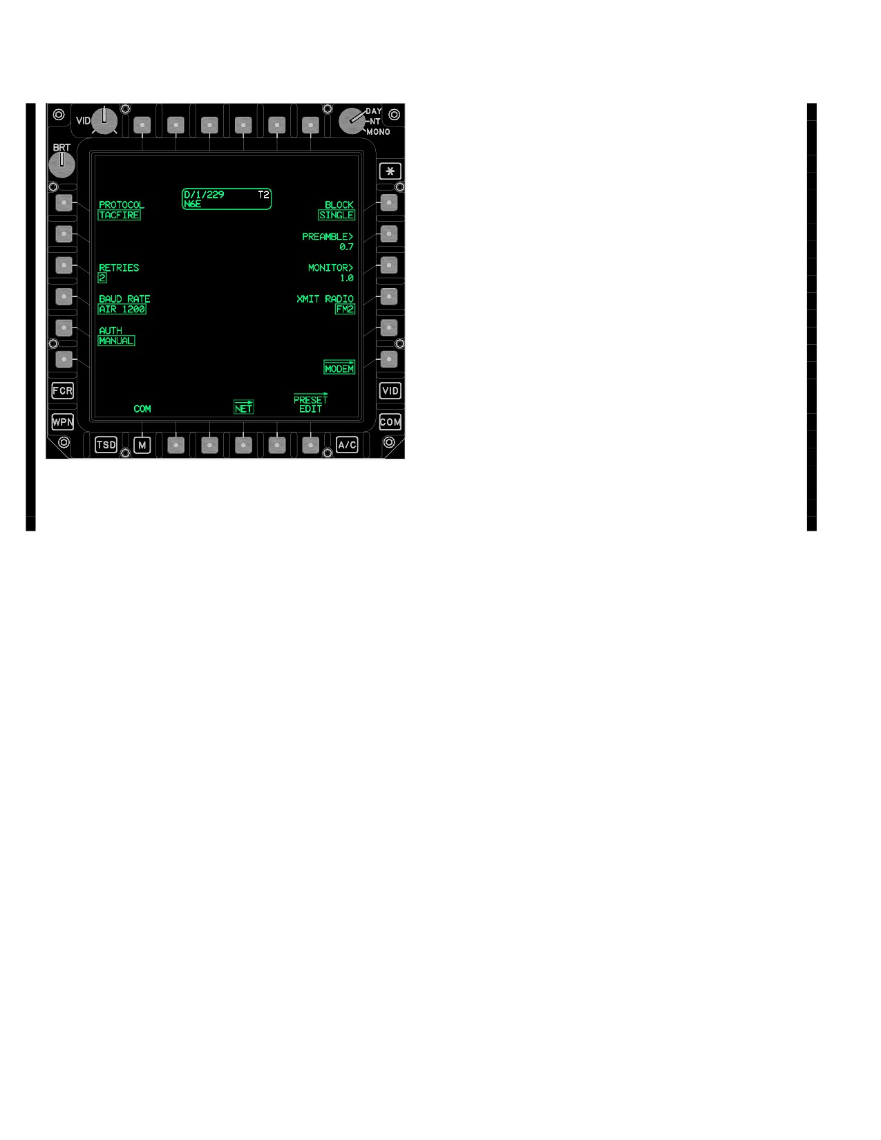
nicate with an AIR net or TFR net. Refer to figure 3A-22
for all the button descriptions of the MODEM page.
The TACFIRE’s AIR (aircraft) or TFR (TACFIRE - artillery)
mode control is accomplished through the BAUD RATE
LBA5229A
button. To enable the AIR mode select an AIR baud rate
option (L1-L6), to enable the TACFIRE - Artillery mode se-
Figure 3A-86. ORIG ID Page TACFIRE Settings
lect a TACFIRE baud rate option (R1-R2) as required.
Use or disclosure of this information is subject to the restriction(s) on the title page of this document.
Change 3
3A-87
TM 1-1520-251-10
3A.71.4 Artillery TACFIRE Parameter Premission
Planning Considerations.
a. General. To increase the probability of success-
ful TACFIRE message exchanges with the artillery, the
observer/designator’s aircraft settings must be identical to
those used by AFATDS. It is also critical to ensure that the
FM1 or FM2 radio used with artillery TACFIRE messaging
is set to CIPHER. AFATDS requires CIPHER to enable its
automatic acknowledgement of an observer/designator’s
TACFIRE message. Without the receipt of machine
ACKS, the IDM could re - transmit multiple copies of the
same message and create duplicate missions. The com-
mon indication in the crew station of an incompatible
AFATDS setting, assuming the aircraft is within LOS, is
that the observer/designator’s platform will not display
ACKS.
b. AFATDS Pre - Mission Settings. The attack heli-
copter unit’s TOE or OPCON Fire Support Officer (FSO),
will normally be responsible for obtaining and distributing
LBA5231
the artillery’s TACFIRE configuration settings. The TAC-
FIRE data distributed by the FSO represent the configura-
tion settings of a specific Artillery unit’s Fire Direction Con-
Figure
3A-88.
MODEM Page TACFIRE Protocol
trol (FDC) and battery’s AFATDS devices.
Use or disclosure of this information is subject to the restriction(s) on the title page of this document.
3A-88
Change 3
TM 1-1520-251-10
NOTE
The unique artillery TACFIRE mode format for
the WEAPONS STATUS Page (for a SUB-
• All artillery TACFIRE operations must be
SCRIBER/MEMBER) and PRESENT POSI-
conducted over a secure (CIPHER) net to
TION STATUS Page (for a SUBSCRIBER/
enable AFATDS machine-ACK mes-
MEMBER) are automatically updated upon
sages.
receipt of a Situation/Status Report and will dis-
• The artillery’s TACFIRE net mode will
play the following mode unique format:
only support subscriber IDs that begin
with with a zero ( 0 - 9, 0 - Z).
a. The WEAPONS STATUS Page (for SUB-
• Prior to conducting TACFIRE operations
SCRIBER) for a TACFIRE (TFR) net contain
with the artillery, perform a voice commu-
only the two laser codes.
nications check with AFATDS and a
FREE TEXT message.
b. The PRESENT POSITION STATUS Page
c. AFATDS Mission Settings. The FDC’s AFATDS
(for SUBSCRIBER) for a TACFIRE (TFR)
has to include the TACFIRE compatible type device that
net contain only UTM and ALT. The SITREP
each of its subscribers are using loaded in its database.
is essentially a position report for the Artil-
AFATDS currently does not have an IDM type device set-
lery.
ting so they should assign the IDM platform as an ATHS
device. If they assign an IDM user as a FED type device
NOTE
the way that targets are recorded may become an issue.
AFATDS uses some different configuration and data han-
• The AFATDS SINCGARS-ICOM radio
dling techniques based on the device that it is communi-
datarate is set to a “TF” data rate while
cating with. If the observer is recorded as an ATHS type,
the aircraft SINCGARS data rate and
EOM RAT correctly causes the previously assigned target
mode is automatically set anytime that
number (e.g., AA2345) to be moved to a separate target
the TACFIRE preset - net MODEM BAU-
list for later reference called EOM RAT - T processing. If
DRATE is set to TACFIRE 1200.
the observer is recorded as a FED type, End Of Mission
Record as Target (EOM RAT) causes an incompatible as-
• Aircraft Error Control is automatically set
signment of a Known Point Number (K) called EOM
to EDC/TDC when a TACFIRE BAUD
RAT - K processing. The following parameters are com-
RATE is selected: the artillery may state
mon artillery TACFIRE (FED/ATHS) settings:
EDC/TDC as a value in pre - mission in-
structions.
NOTE
Information contained in parenthesis with an
5.
AUTH (*AUTHENTICATION) - N/A Not in use.
asterisk (*) are the equivalent Field Artillery
AFATDS term translations for those used by
the IDM and aircraft.
6.
BLOCK (*BLOCK MODE) - SINGLE.
1. TACFIRE preset - net FM1 or FM2 MODE - CI-
PHER (*SECURE) using a common CNV.
7.
PREAMBLE (*KEY TIME) - 1.4 sec or as re-
quired. This may need to be increased to ensure
radio communications. Key times of less than
2. FM single channel frequency or SINCGARS
1.4 have occasionally caused AFATDS to re-
hopset (*NET ID) - set as required.
ceive duplicate transmissions from the ATHS
platform.
3. RETRIES - Select a low setting of 0 or 1.
4. MODEM page BAUD RATE (*DATA ENCOD-
8.
MONITOR TIME (*NET ACCESS DELAY) is
ING) -select TACFIRE 1200 (*TFR or FSK
typically set at 1.0
1200). The artillery TACFIRE page format is
moded by the IDM whenever a TACFIRE baud
rate is selected from the MODEM page.
9.
XMIT RADIO - TUNE FM1 or FM2 in CIPHER.
Use or disclosure of this information is subject to the restriction(s) on the title page of this document.
Change 3
3A-89
TM 1-1520-251-10
3A.71.5 Air to Air TACFIRE Parameter Premission
3A.71.6
ATHS TACFIRE Operations.
Planning Considerations.
a. General. To increase the probability of success-
ful Air to Air TACFIRE message exchanges, all aircraft op-
erating on the same TACFIRE net should typically have
the same settings. The following settings are common
configuration settings:
1.
TACFIRE preset - net FM1 or FM2 MODE - CI-
PHER (CNV1 - 6) or PLAIN - set as required.
2.
RETRIES - Set as required.
3.
MODEM page BAUD RATE and MODE. Typi-
cally, aircraft will utilize the AIR NET mode pa-
rameters by selecting a MODEM page BAUD
RATE of AIR 1200. Other optional selections in-
clude AIR 600, AIR 300, AIR 150, or AIR 75.
The unique AIR mode format for the WEAPONS
STATUS Page (for a SUBSCRIBER/MEMBER)
LBA5232
and PRESENT POSITION STATUS Page (for a
SUBSCRIBER/MEMBER) are automatically up-
dated upon receipt of a Situation/Status Report
Figure
3A-89.
ATHS Page TACFIRE Index Format
and will display the following mode unique for-
mat:
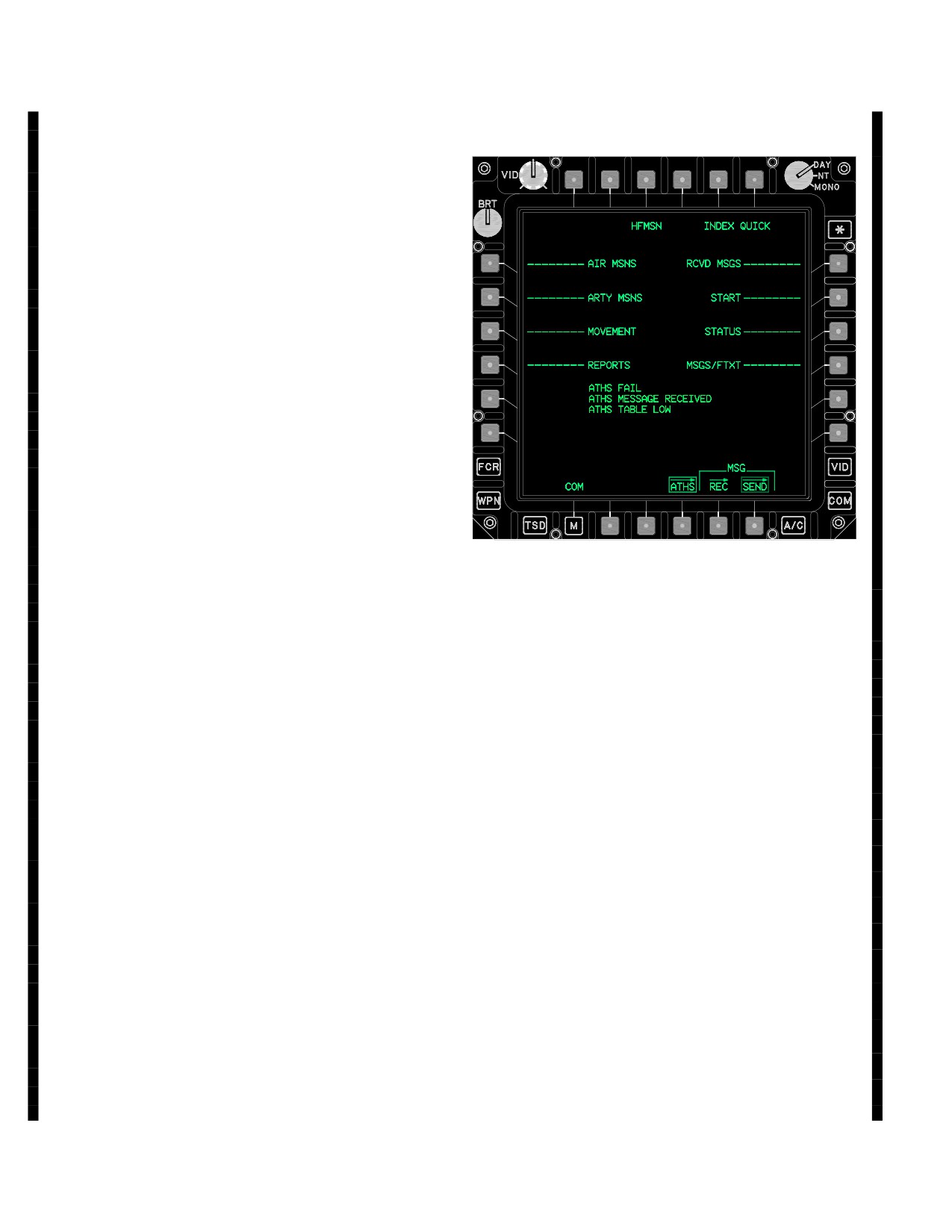
a. INDEX Page. A total of eight (8) separate sec-
tions may be accessed from the INDEX page. The 8 sec-
a. The WEAPONS STATUS Page (for SUB-
tions are displayed with associated line - keys, a series of
SCRIBER/MEMBER) for an AIR net con-
dashes, aligned with specific L1 - L4 or R1 - R4 MPD vari-
tains COD1 and COD2 (two laser codes),
able action buttons. The 8 sections and associated but-
ATGM, A/A, RKTS, and gun AMMO.
tons include:
b. The PRESENT POSITION STATUS Page
• L1
AIR MSNS
(for SUBSCRIBER/MEMBER) for an AIR
• L2
ARTY MSNS
net contain UTM, ALT, FUEL (fuel remain-
ing), and also TEAM and BC addresses.
• L3
MOVEMENT
• L4
REPORTS
4.
AUTH - N/A Not in use.
• R1
RSVD MSGS
• R2
START
5.
BLOCK - SINGLE.
• R3
STATUS
6.
PREAMBLE - 1.4 sec or as required This may
• R4
MSGS/FTXT
need to be increased to ensure radio commu-
nications.
b. Common ATHS - TACFIRE Buttons. In addition
to the 8 line key sections three unique buttons are dis-
played on all the ATHS - TACFIRE pages.
7.
MONITOR - is typically set at 1.0.
• T3
HFMSN
8.
XMIT RADIO - TUNE radio as required: 1) VHF;
• T5
QUICK
of 2) UHF (HAVQUICK or SC); or 3) FM1/FM2
SINCGARS (hopset or SC).
• T6
INDEX
Use or disclosure of this information is subject to the restriction(s) on the title page of this document.
3A-90
Change 3
TM 1-1520-251-10
operator interface functionality of specific fields. When
manual entry of information is required, a greater than (>)
or less than (<) sign will appear which points away from
the associated line key to signify that operator input must
be made using the KU (the ENTER key is required). If only
limited choices are available and rapid selectivity is re-
quired, a caret (^) will be present beside the key field of
information pointing upward. Pressing this line key will
scroll through each available option. The “*” defines which
line is active for paging or keyboard data input. When the
crew selects a line for data entry but the MPD button se-
lected is not the current data entry line (does not display
an asterisk), the DP will output the appropriate keyboard
character to the TACFIRE until this line becomes the cur-
rent data entry line, as designated by the asterisk charac-
ter “*”. Once the current data entry line is detected, the DP
will then output the appropriate keyboard character to the
ATHS. A double pound sign (##) indicates a numeric entry
button. A double ampersand sign (@@) indicates alpha
character entry button.
LBA5233
3A.71.8 HFMSN Button (T3). When participating in a
shooter role, the HFMSN button (T3) is selected (boxed)
by the operator upon receipt of an AIR MSN message and
Figure
3A-89A.
ATHS - TACFIRE RCVD MSGS Page
deselected at other times.
c. ATHS - TACFIRE Advisories. The ATHS INDEX
3A.71.9 QUICK Button (T5). Selecting the QUICK but-
ton (T5) provides direct access to various previous/preset
page reserves the data area beneath the last two line keys
for ATHS-TACFIRE specific advisories. ATHS INDEX
messages. The QUICK button appears on all the ATHS -
page caution/advisories include:
TACFIRE pages and provides direct access to any one of
the following menu items:
• ATHS MESSAGE RECEIVED
• Summary Page of Highest Priority Received
• ATHS TABLE LOW (no longer used by the
Message.
artillery)
• Airborne Mission Summary Page.
• ATHS FAIL
• Artillery Mission Summary Page.
ATHS MESSAGE RECEIVED indicates that an ATHS -
TACFIRE message has been received. ATHS TABLE
• Mayday Message Summary Page.
LOW indicates the authentication tables have less than
• Quick Menu Page.
20 available lines remaining; however, the artillery no lon-
ger uses the table. ATHS FAIL indicates the IDM ATHS -
3A.71.10 INDEX Button (T6). Selecting the INDEX
TACFIRE component has failed.
button (T6) provides direct access to the ATHS - TACFIRE
INDEX page para 3A.71.6.
3A.71.7 General ATHS - TACFIRE Button Con-
trol. The TACFIRE message format Left and Right mo-
mentary buttons are displayed whenever the ATHS page
3A.71.11 SEND button (R5). Selecting the SEND but-
is selected. The selection of a TACFIRE Left or Right mo-
ton will transmit the selected TACFIRE message to the
mentary button initiates the requested TACFIRE format
subscriber/ member displayed within the subscriber data
paging, data entry, or other selection in accordance with
ID bloc adjacent to the L1 linekey. The SEND button is dis-
the current TACFIRE button option selection. The TAC-
played on any of the ATHS - TACFIRE pages where the
FIRE pages employs a set of ASCII characters to denote
destination subscriber data ID bloc is displayed.
Use or disclosure of this information is subject to the restriction(s) on the title page of this document.
Change 3
3A-91
TM 1-1520-251-10
NOTE
b. The ATHS (TACFIRE) START page (R2) should
only be accessed under the following conditions:
The START page button description is listed
out of sequential button order to facilitate
(1) When conducting single aircraft training and a
the contiguous description of all the ATHS -
different/net radio needs to set for receiving messages
TACFIRE message buttons, and to rein-
sent from/to the ownship.
force a systems ordered approach to how/
when AH-64D operators interface with
(2) Possible maintainer requirement to view the
ATHS - TACFIRE parameters.
IDM IP address for loading purposes and to view a de-
tailed IDM listing of the various software and firmware
3A.71.12 START PAGE Button - Description.
module versions on START (R2), RESET DATA> (R3),
<SW - VERS (L4) 1/4 pages.
NOTE
(3) If it is necessary to prepare/edit any of the six
• Do not use the START pages to perform
message preset selections or any of the six movement
TACFIRE NET management.
preset selections.
• The RESET line - key button should not
NOTE
be used if it is desired to maintain the TI
situational awareness icons.
When it is necessary to RESET the TAC-
FIRE resident data in the IDM, it is recom-
• The RESET line-key button will clear
mended to access the SET page and select
TACFIRE and Longbow ORIG ID, BC
the ZEROIZE button in place of accessing
and TM ID, remove TM status for mem-
the ATHS START page RESET button.
bers in a TACFIRE NET, and SA DATA.
These buttons support identical functional-
ity.
a. The ATHS - TACFIRE’s START page (R2) paging
structure is the sole means by which operators of non - in-
c. The START page RESET line - key button clears all
tegrated legacy aircraft edit TACFIRE ownship ID, BC/TM
data and table entries from the IDM ATHS-TACFIRE
ID, TACFIRE nets, and TACFIRE protocol parameters.
component and the Longbow ORIG ID. Following a REST,
AH - 64D operators should always utilize the same COM
any COM page preset TACFIRE net will have to be se-
subpages that are used to manage all the other digital pro-
lected and any pertinent members will have to be redesig-
tocols when working with the TACFIRE protocol.
nated as TM members following a ZEROIZE.
Use or disclosure of this information is subject to the restriction(s) on the title page of this document.
3A-92
Change 3
TM 1-1520-251-10
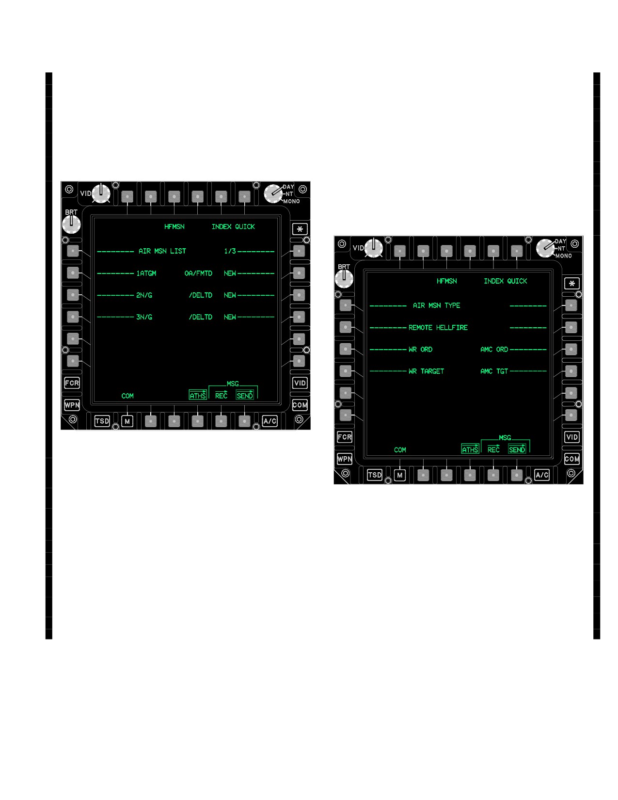
3A.71.13 AIR MSNS Page (INDEX Page L1). The AIR
to which request was sent, and mission status in line with
MSN LIST page is displayed upon selecting the AIR
the mission number (1 - 8). Stepping through the air re-
MSNS button (L1) from the INDEX page (figure 3A-89).
quest list is accomplished by pressing the R1 key on the
The AIR MSN LIST page is capable of storing eight spe-
MFD. The following mission command and status entries
cific AIR (fire) MISSION requests in the IDM. To request
may be displayed.
and respond to airborne fire missions. NEW air or HELL-
• R2 - R4
XXXX or XN/G (3 pages).
FIRE missions may be defined or existing missions modi-
fied through the AIR MSN (REQUEST) LIST pages.
Pressing the right line keys adjacent to NEW accesses the
AIR MISSION TYPE page for initiating new STANDARD
or HELLFIRE air mission requests.
3A.71.14 AIR MSN TYPE Page.
LBA5234
Figure 3A-89B. AIR MSN (REQUEST) LIST Page
AIR MSN LIST selections include:
LBA5235
• L2 - L4
XXXX or #N/G (3 pages).
Figure 3A-89C. AIR MSN TYPE Page
Pressing the left line keys adjacent to the desired mission
number LIST pages accesses the previously established
Fire mission selections include:
air mission request pages. Upon selection, complete mis-
sion request information is displayed. #N/G represents
• L2
REMOTE HELLFIRE (para. 3A.71.24).
#NOT/GIVEN where there is no previous data entered.
• L3
AMC ORDNANCE (para. 3A.71.25).
• R1
1/3 to 3/3 (3 pages).
• L4
WR ORDNANCE (para. 3A.71.26).
• R3
AMC TARGET (para. 3A.71.27).
The three AIR MSN (REQUEST) LIST pages 1/3 through
3/3 display mission command, firing element (subscriber)
• R4
WR TARGET (para. 3A.71.28).
Use or disclosure of this information is subject to the restriction(s) on the title page of this document.
Change 3
3A-93
TM 1-1520-251-10
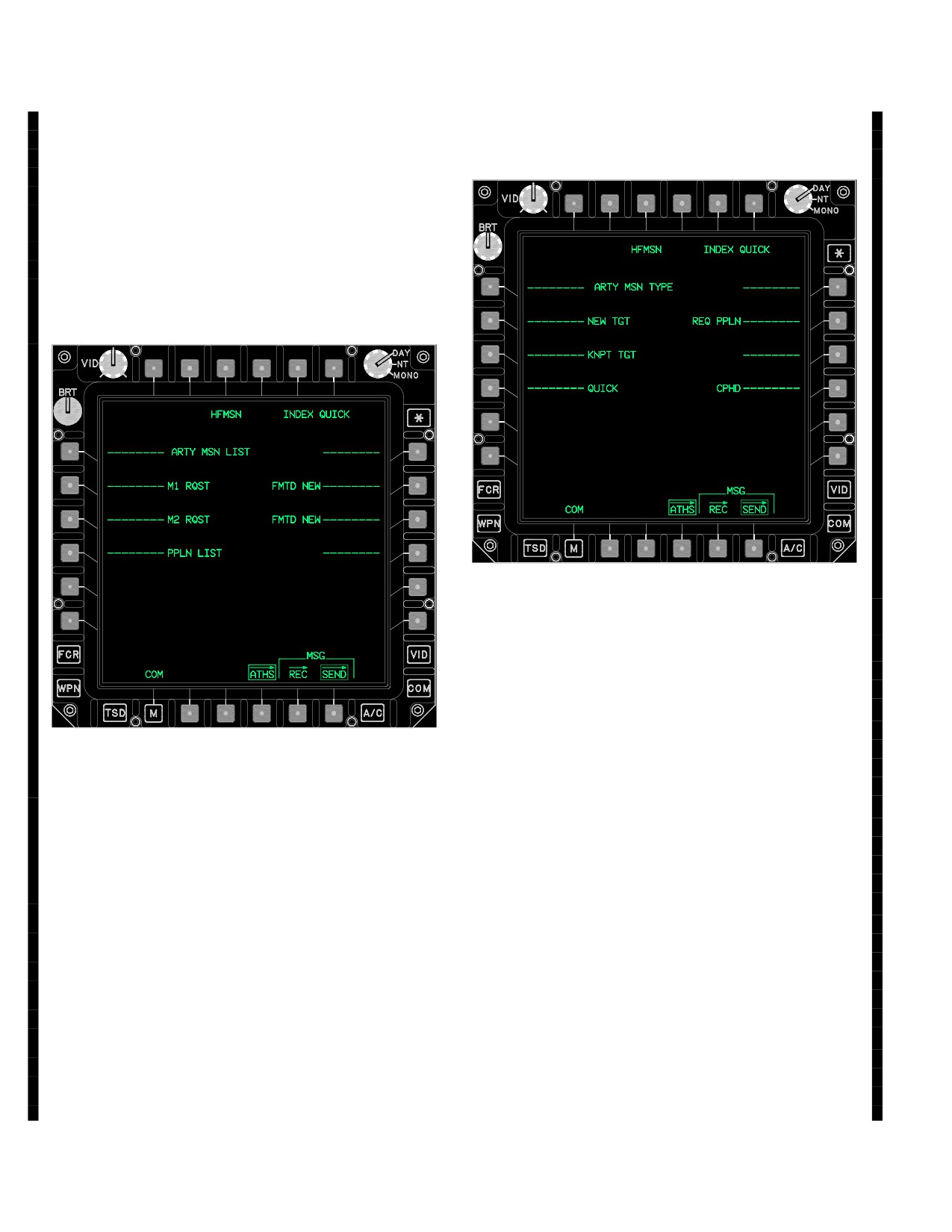
3A.71.15 ARTY MSNS Page (INDEX Page L2). The
3A.71.16 ARTY MSN TYPE Page. The ARTY MSN
ARTY MSN LIST page is displayed upon selecting the
TYPE page is displayed upon selecting either of the
ARTY MSNS button (L2) from the INDEX page (figure
ARTY MSN LIST pages FMTD NEW buttons.
3A-89). ARTY MSN LIST page enables observer/desig-
nators to request and respond to artillery fire missions.
Supports 2 preplanned (preformatted) artillery missions, 2
new artillery missions, and allows the modification of ex-
isting missions. Artillery mission data is formatted to be
consistent with the artillery FDC and forward observer
DMD.
LBA5237
Figure 3A-89E. ARTY MSN TYPE Page
ARTY MSN TYPE page buttons include:
• L2
NEW TGT (new target) - The Observer
defines the Target type and the strength
for a new Target.
• L3
KNPT TGT (Known Point target) - A
LBA5236
location previously identified and num -
bered, known both to the requester and
to the artillery FDC. The requester then
Figure 3A-89D. ARTY MSN LIST Page
provides the Target type and strength.
• L4
QUICK (quick fire) - The requester
enters only a Known Point or a Target
Number. All other data is known by the
ARTY MSN LIST page buttons include:
artillery FDC. (Target Number is the
preferred method).
• L2
M1 RQST - Preplanned mission #1.
• R2
REQ PPLN (preplan) - The Observer
• L3
M2 RSST - Preplanned mission #2.
provides the type of fire request either
FPF or CPHD guided munitions. Only
• L4
PPLN LIST - Accesses the preplaned
one FPF can be preplanned at a time;
list.
however, both preplanned missions can
• R2
FMTD NEW - Opens ARTY MSN TYPE
be CPHD. The requester then provides
page (figure 3A-89E).
the Target position.
• R4
CPHD (COPPERHEAD) - The Target
• R3
FMTD NEW - Opens ARTY MSN TYPE
position is defined as NEW TGT or
page (figure 3A-89E).
KNPT and Known Point number is
• R3
FMTD NEW - New ARTY mission.
provided to the firing element.
Use or disclosure of this information is subject to the restriction(s) on the title page of this document.
3A-94
Change 3
TM 1-1520-251-10
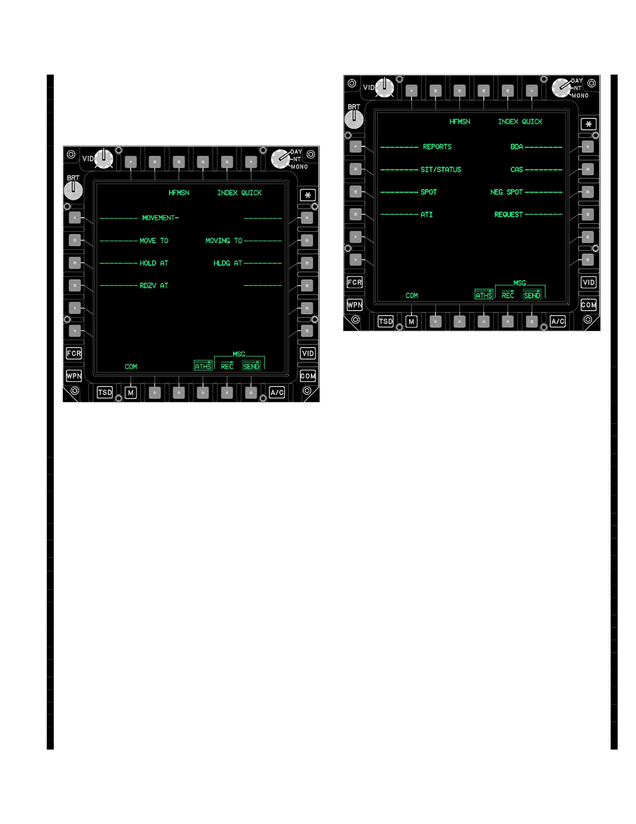
3A.71.17 MOVEMENT Page (INDEX L3). The MOVE-
MENT page is displayed upon selecting the MOVEMENT
button (L3) from the INDEX page (figure 3A-89). Allows
position instructions to be given without the use of voice
communications.
LBA5239
Figure 3A-89G. REPORTS Page
REPORTS page button options are:
LBA5238
• L2
SIT/STATUS (Situation/Status) - States
Figure 3A-89F. MOVEMENT Page
the operator’s own situation and status.
• L3
SPOT (Positive Spot) - Reports target
MOVEMENT page button options are:
activity.
• L2
MOVE TO.
• L4
ATI (Artillery Target Intelligence) - Pro -
• L3
HOLD AT.
vides intelligence to artillery units.
• L4
RDZV (rendezvous) AT.
• R1
BDA (Battle Damage Assessment) -
• R2
MOVING TO.
Provides battle damage assessment to
• R3
HLDG (holding) AT.
artillery or AIR MSN controlling units.
Selecting any of the MOVEMENT page options will dis-
• R2
CAS (Casualty) - Provides casualty
report capability.
play 3 movement destination/location options:
• R3
NEG SPOT (Negative Spot) - Provides
• L2
PRESET - Permits selection of any six
no target activity.
preset positions.
• R4
REQUEST REPORT - Requests reports
• L3
MY POSITION - Enables automatic
from destination net subscriber/members.
transmission of own current position.
The following reports may be requested
• L4
OTHER - Enables freetext communica-
from other subscriber/members.
tions.
• L2
SIT/STATUS (Situation/Status).
3A.71.18 REPORTS Page (INDEX L4). The RE-
PORTS page is displayed upon selecting the REPORTS
• L3
SPOT (Spotter).
button (L4) from the INDEX page (figure 3A-89). Permits
• R2
BDA (Battle Damage Assessment).
the ownship to provide information to both team and
• R3
CAS (Casualty).
broadcast net members. The following reports are se-
lectable from the REPORT TYPE SELECT page.
• R4
POS UPDT (Automatic Position Update).
Use or disclosure of this information is subject to the restriction(s) on the title page of this document.
Change 3
3A-95
TM 1-1520-251-10
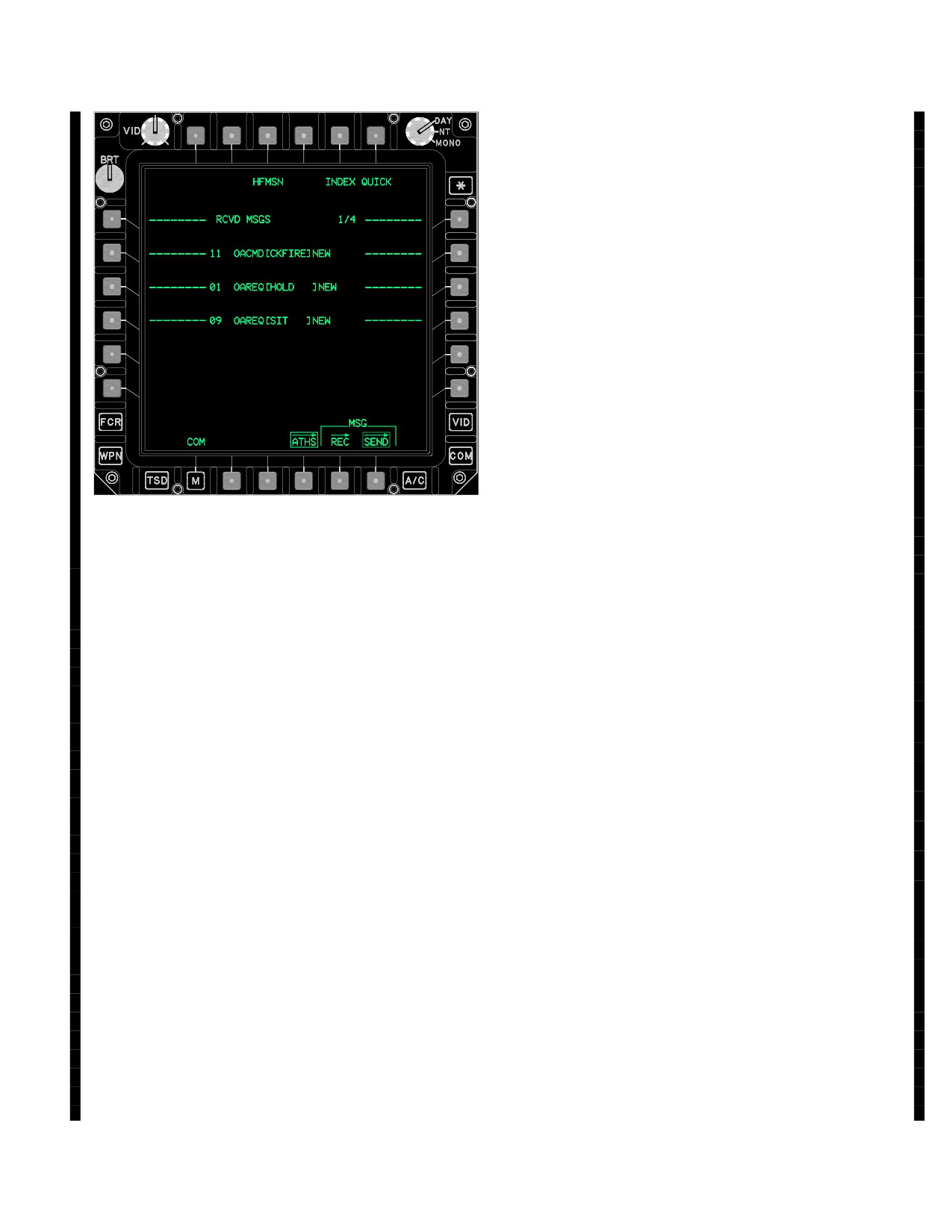
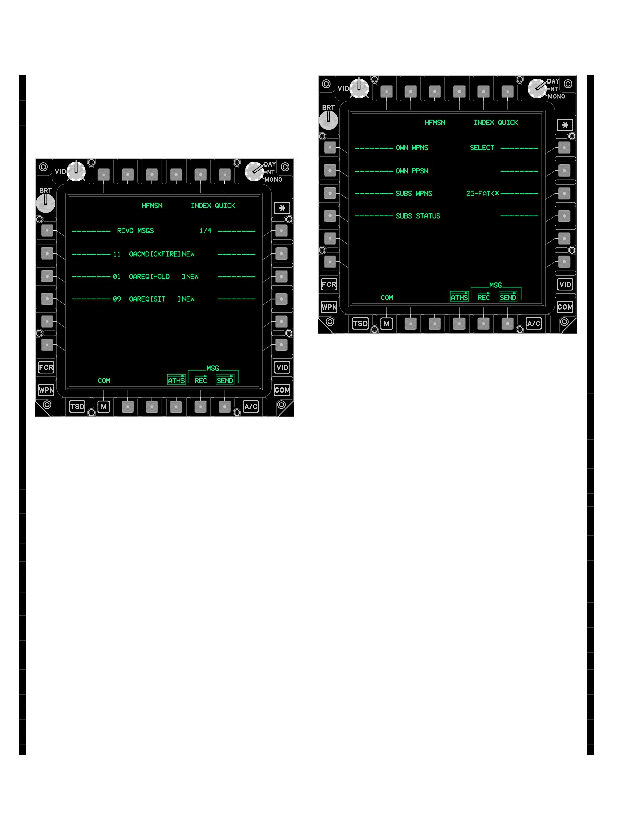
3A.71.19 RCVD MSGS Page (INDEX R1). The RCVD
MSGS page is accessed by selecting either the RCVD
MSGS button (R1) from the INDEX page (fig 3A-89) or the
MSG RCV page RVW button when an ATHS MSG (TAC-
FIRE) message is selected.
LBA5241
Figure 3A-89I. STATUS Page
Status page button option buttons:
• L1
OWN WPNS - WEAPONS STATUS
LBA5240
page (for OWN) containing information
of own weapons stores.
Figure 3A-89H. RCVD MSGS Page
• L2
OWN PPSN - PRESENT POSITION
STATUS page (for OWN) containing
information on own position, altitude,
The RCVD MSGS page allows the operator to:
fuel status, and current team and broad-
cast addresses.
• R1
1/1 - X/16 - Access the message page
listing (up to 16 pages).
• L3
SUBS WPNS - WEAPONS STATUS
page (for SUBSCRIBER). There is a
• L1 - L3
Review newly received messages.
separate WEAPONS STATUS page (for
• L1 - L3
Review previously retained messages
SUBSCRIBER) for each defined sub -
(12 - 48 = 12 for each TACFIRE radio).
scriber in the net.
• L1 - L3
Delete messages no longer needed.
• L4
SUBS STATUS - PRESENT POSI -
TION STATUS page (for SUBSCRIB-
Received messages review pages displaying DEL or DE-
ER). There is a separate PRESENT
LETE next to a line key may be deleted from the page
POSITION STATUS page (for SUB -
where they are reviewed.
SCRIBER) for each defined subscriber
in the net.
3A.71.20 STATUS Page (INDEX R3). The STATUS
• R1
SELECT - STATUS SUBSCRIBER
page is displayed upon selecting the STATUS button (R3)
SELECT page. This page permits the
from the INDEX page (fig 3A-89). Displays OWN (OWN-
operator to access position and weap -
SHIP) WPNS and PPSN data that is sent with the sending
ons status information from a particular
of a SITREP from the OWNSHIP and displays the SUBS
subscriber, rather than stepping through
(Subscriber/member) WPNS and STATUS when SI-
the status of all defined subscribers in
TREPS have been received.
listed order.
Use or disclosure of this information is subject to the restriction(s) on the title page of this document.
3A-96
Change 3
TM 1-1520-251-10
• R3
XX - FAT<* - Displays the free air tem -
perature (FAT) ( - 43 to 80 degrees C).
Enters the FAT.
All subscriber data will be displayed using one of two for-
mats: 1) AIR; or 2) TACFIRE (TFR). The WEAPONS STA-
TUS page (for SUBSCRIBER) and PRESENT POSITION
STATUS page (for SUBSCRIBER) are different depend-
ing upon whether the subscriber is defined in an AIR or a
TACFIRE (TFR) format type. The formats are automati-
cally set in association with the MODEM page BAUD
RATE type selection: an AIR baud rate e.g., AIR 1200,
sets the AIR format; and A TACFIRE format e.g., TAC-
FIRE 1200, sets the TACFIRE format.
The WEAPONS STATUS page (for SUBSCRIBER) for an
AIR baud rate net contains COD1 and COD2 (two laser
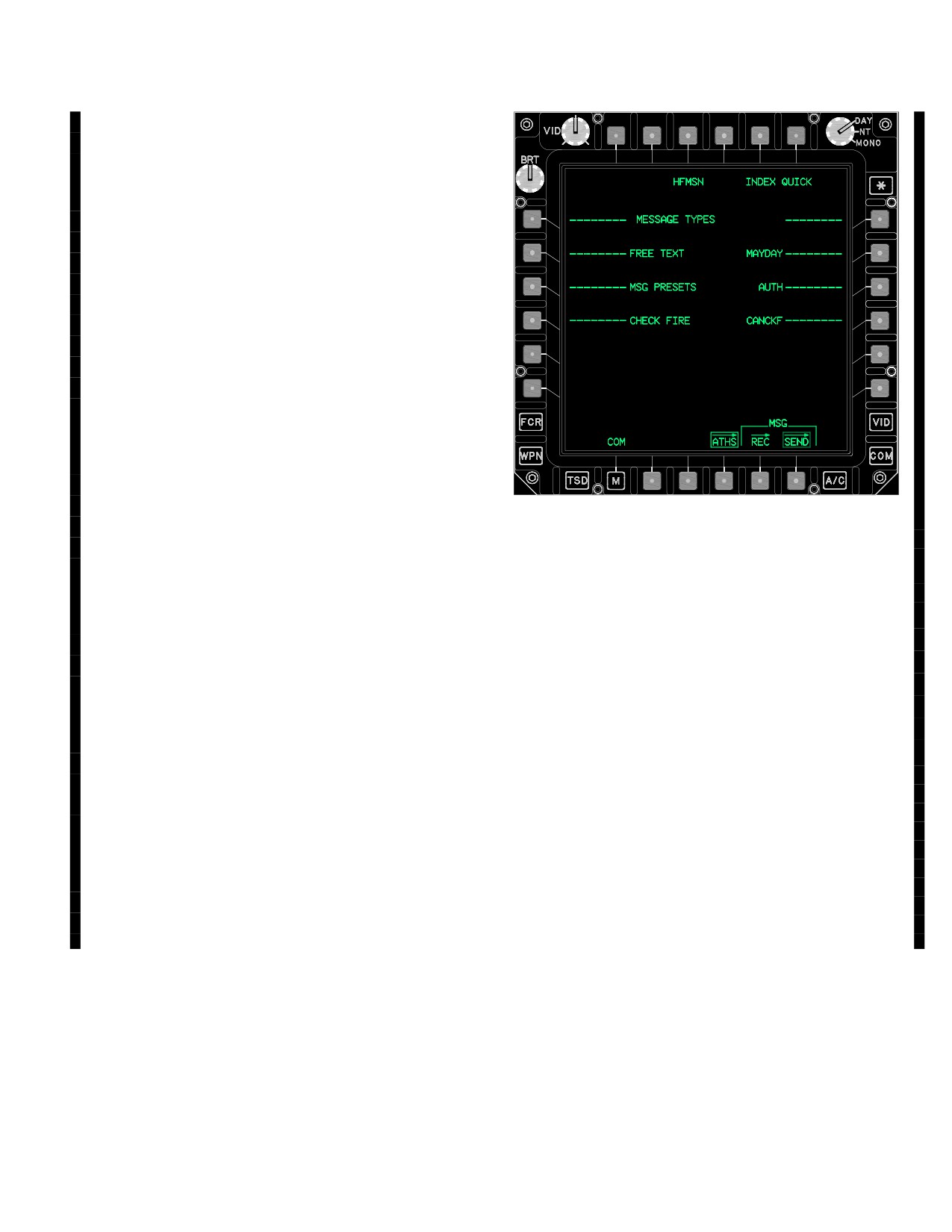
LBA5242
codes), ATGM, A/A, RKTS, and gun AMMO. The WEAP-
Figure 3A-89J. MSGS/FTXT (MESSAGE TYPES)
ONS STATUS page (for SUBSCRIBER) for a TACFIRE
Page
(TFR) baud rate net contain only the two laser codes.
MSGS/FTXT page (MESSAGE TYPES) button options in-
clude:
• L1
FREETEXT
The PRESENT POSITION STATUS page (for SUB-
• L2
MSG PRESETS
SCRIBER) for an AIR net contain UTM, ALT, FUEL (fuel
remaining), and also TEAM and BC addresses.
• L3
CHECK FIRE
• R2
MAYDAY
• R3
AUTH (authentication)
• R4
CANCKF (CANCEL CHECK FIRE)
The PRESENT POSITION STATUS page (for SUB-
3A.71.22 Air and Artillery Message Sets. The Air
SCRIBER) for a TACFIRE (TFR) baud rate net contain
mode net of TACFIRE and the Artillery mode net of
only UTM and ALT. The SITREP is used as a PP report
TACFIRE supports different message sets. For Air
with the artillery.
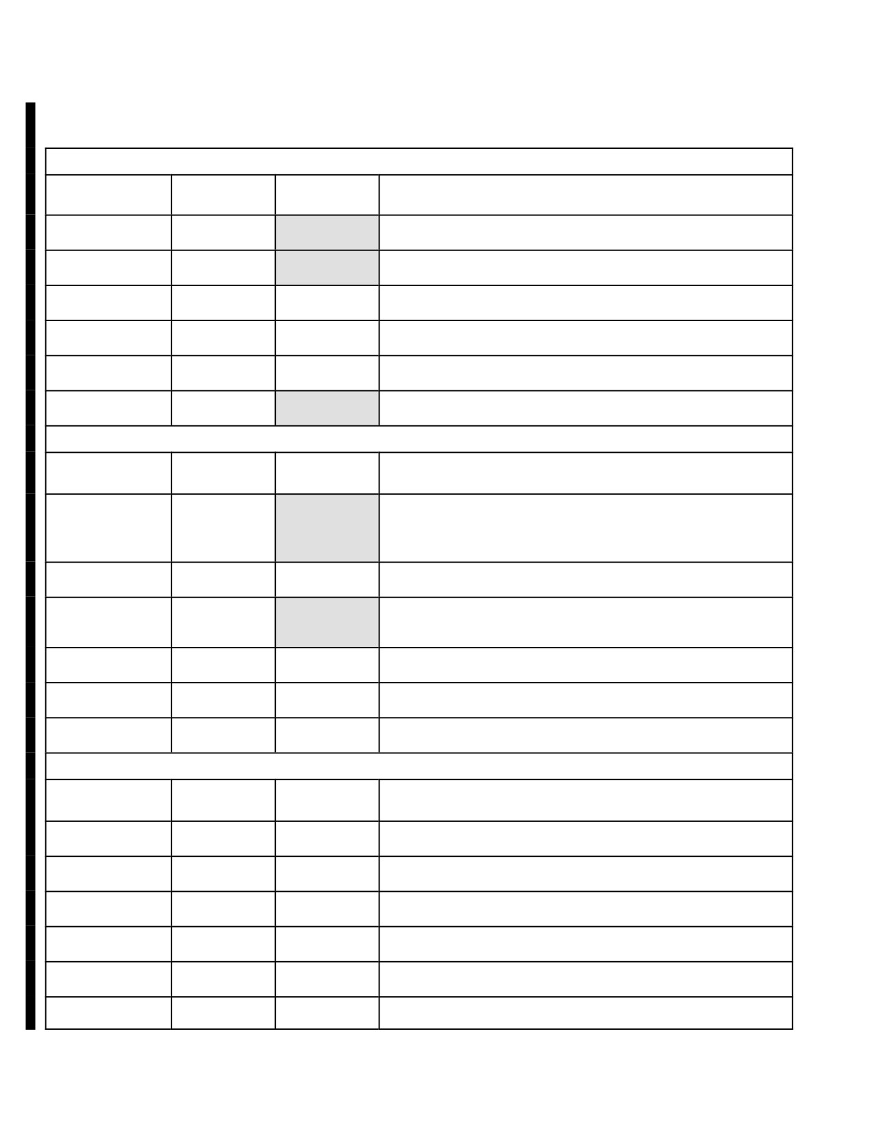
and Artillery message capability (refer to table
3A-4E). When sent to AFATDS, some of the message
types will respond with an ACK even though nothing is ac-
tually received and displayed by AFATDS. A message
3A.71.21 MSGS/FTXT Page (INDEX R4). Permits the
such as a SITREP request will not provide an ACK. The
operator to compose and transmit any preset/free text
STATUS page has to be accessed to determine the re-
message up to 35 characters at a time.
sponse by checking subscriber / member data.
Use or disclosure of this information is subject to the restriction(s) on the title page of this document.
Change 3
3A-97
TM 1-1520-251-10
Table 3A-4E. Air and TACFIRE mode message compatibility
MSGS/FTXT
Type
Receive an
Received by
Remarks
AFATDS ACK
AFATDS
FREE TEXT
Yes
Yes
Air and Artillery
MSG PRESETS
Yes
Yes
Air and Artillery
CHECKFIRE
Yes
No
Send Checkfire by voice (known issue)
MAYDAY
No
No
Air only
AUTH
N/A
N/A
Message format no longer used
CANCKF
Yes
Yes
Automatically processed by AFATDS
REPORTS
Type
Receive an
Received by
Remarks
AFATDS
AFATDS
SIT/SAT
Yes
Yes
Air and Artillery. Automatically updates location; however, in the
artillery TAC FIRE mode fuel, laser code, and ammo are not
updated as they are in AIR mode.
SPOT REPORT
Yes
No
Air only (arty ACK but no msg receipt)
ARTY
Yes
Yes
Artillery only. No message is generated - - target goes into the
AFATDS suspect target list
BDA/CAS
Yes
No
Air only (or as part of Artillery thread)
NEG SPOT
Yes
No
Air only (arty ACK but no msg receipt)
REQUEST
No
No
Air only (arty ACK but no msg receipt)
MOVEMENT
Type
Receive an
Received by
Remarks
AFATDS ACK
AFATDS
MOVE TO
No
No
Air only
HOLD AT
No
No
Air only
RDZV AT
No
No
Air only
MOVING TO
No
No
Air only
HOLD AT
No
No
Air only
No
No
Air only
Use or disclosure of this information is subject to the restriction(s) on the title page of this document.
3A-98
Change 3
TM 1-1520-251-10
3A.71.23 Target/Position Buffer Coordinate Auto-
3A.71.24 Remote HELLFIRE (Aircraft Remote HELL-
fill. A number of AIR and ARTY messages allow the op-
FIRE Mission).
erator to automatically populate target and other coordi-
nate data into a message. This is normally accomplished
OBSERVER/DESIGNATOR: (REMOTE HELLFIRE).
using the TSD page and the CAQing of any WPTHZ,
CTRLM, or TGT/THRT. Following a SET page ZEROIZE
1.
Locate target using aircraft sensors and use
or an ATHS START page “RESET“ the applicable TAC-
TSD CAQ as necessary for automatic entry of
FIRE message coordinates will not contain any displayed
target coordinates.
values until the operator provides them. A new feature im-
plemented for non - integrated platforms, referred to as the
2.
ATHS page (B4) - Select as required.
Common Target Position Buffer (CTPB), will often require
3.
INDEX button (T5) - Select as required.
AH - 64D operators to select the 2.9I TACFIRE UPD GRD
(UPDATE GRID) button (R4) to overwrite an existing
4.
Select AIR MSNS.
coordinate value. The UPD GRD button has to be se-
lected, anytime that a valid grid coordinate is displayed in
5.
Select Mission 1 on AIR REQ List Pages 1/3 by
the grid reference component of an applicable message.
pressing NEW. (fig 3A-89B).
6.
On MSN TYPE Page - Select REMOTE HELL-
NOTE
FIRE.
• If an existing coordinate will not permit an
AUTO UPDATE with CAQing, select the
7.
On AIR MISSION SUMMARY page.
2.9I TACFIRE UPD GRD (UPDATE GRID)
button (R4) where displayed on the various
a. Evaluate/set coordinates (R4) as required.
coordinate pages (the REMOTE HELL-
b. Evaluate/set Target Type (R3) as required.
FIRE page does not support this feature).
c. Evaluate/set Target Activity (R4) as re-
The reports and missions that use the Target/Position
quired.
Buffer coordinate autofill fields are:
d. Press R2 to access AIR CONTROL SUM-
• AIR MISSION (Target Position)
MARY page.
• AIRBORNE SPOT REPORT (Target Position)
8.
On AIR CONTROL SUMMARY page.
• AIRBORNE NEGATIVE SPOT REPORT (Report
a. Evaluate MST (L1) for multiple missiles.
Position, only on operator initiated CAQ, initially
set to OWN Present Position)
b. Evaluate/set Laser Code/Rounds (L3) - as
required.
• AIRBORNE CAS REPORT (Report Position only
on operator initiated CAQ, initially set to OWN
c. Review/set MSL TRAJ (R2) as required.
Present Position)
d. Press R1 to access AIR MISSION SUMMA-
• AIRBORNE BDA REPORT (Report Position)
RY page.
• ARTILLERY (ATI) REPORT (Target Position)
9.
Evaluate/set DEST SUB ID as required.
• ARTILLERY MISSION - Request Phase (Target
10.
Press SEND to request mission.
Position)
NOTE
• ARTILLERY MISSION - Shift Phase, if needed
(Round Position)
• At this point the Observer waits for the
Shooter to send an ACCEPTED mes-
sage.
The Subscriber IDs beginning with a zero (0) are required
for communication with older devices and net specifica-
• This process begins with a RECEIVED
tions especially those using the Artillery TFR net type.
MESSAGE message.
Use or disclosure of this information is subject to the restriction(s) on the title page of this document.
Change 3
3A-99
TM 1-1520-251-10
SHOOTER: (REMOTE HELLFIRE).
In addition to displaying the HELLFIRE symbol modifier
around T52, the selection of the HFMSN button will au-
tomatically code the requested missiles and set the fre-
11.
Receive message.
quencies. The Launcher must then verify the D (LDA)
and S (SEP) angle. The LDA is the laser designation
angle and is the area in front of the launching aircraft
a. MSG RCV page, ATHS MSG select, RVW
that the designating aircraft should avoid. This angle is
button select (will automatically open the
+/- 30 degrees of the launcher gun-target line and will
TACFIRE RCVD MSGS page).
flash at 30 degrees or greater. The S (Separation)
angle is +/- 60 degrees from the target back towards
- or -
the designator aircraft. This is the angle that the desig-
nator should be inside to preclude a missile miss due to
laser angle to the missile. The SEP angle will flash
b. Select ATHS button and INDEX button to
when the angle is greater than 60 degrees. The launch-
access IDM Top Menu page.
er should verify that the target is within range. The
bearing to the target is relative to the launcher in this
12.
Select RCVD MSGS as required.
case and the > indicates the closest direction to turn,
with the amount of degrees required, to the target.
Range and bearing are displayed appropriately for the
13.
To review selected message, press the corre-
aircraft location (launcher and designator). The launch-
sponding LEFT key.
er selects R1 to access page 2/3.
20. Press SEND.
14.
Review/change information on AIR MISSION
SUMMARY page.
NOTE
At this point the Shooter waits for the Ob-
15.
Review/change information on AIR CONTROL
server to send a FIRE message or CHECK
SUMMARY page.
FIRE message.
OBSERVER/DESIGNATOR: (REMOTE HELLFIRE)
16.
Select HFMSN button (T3) - evaluate target
Steps 21 through 28 are CHCKFIRE control procedures.
location with AIR MSN symbol modifier dis-
played around T52 and note that HF missile la-
21. On the OBSERVER: press C: (L2) to access
ser codes have auto - moded or are set as re-
command select page.
quired.
22. Select CHECK FIRE anytime that an operation-
al or safety requirement exists to halt the prog-
17.
Verify Mission Command is ACCEPT or as re-
ress of the mission.
quired on AIR MISSION SUMMARY page. If de-
nied/aborted, the thread will stop upon SEND.
23. Press SEND.
24. Verify receipt by Shooter.
18.
Press SEND.
25. Press C: (L2) to access command select page.
When the situation dictates a need to continue
NOTE
with the progress of the mission or end a mis-
sion.
Upon receipt of the ACCPT, the Observer
waits for the Shooter to send a READY
26. Select CANCKF or END MSN as required.
message.
27. Press SEND.
SHOOTER: (REMOTE HELLFIRE).
28. Verify receipt by Shooter.
NOTE
19. Verify Mission Command is READY on AIR
MISSION SUMMARY page.
If END MSN sent, the thread stops here.
Use or disclosure of this information is subject to the restriction(s) on the title page of this document.
3A-100
Change 3
TM 1-1520-251-10
SHOOTER: (REMOTE HELLFIRE).
3A.71.25 AMC ORDNANCE (Air Request - At My
Command Ordnance).
29. Shooter selects READY (AGAIN) and sends.
OBSERVER/DESIGNATOR: (AMC ORDNANCE).
OBSERVER/DESIGNATOR: (REMOTE HELLFIRE).
1.
Locate target using aircraft sensors and use
Upon receipt of the READY message, perform the following:
TSD CAQ as necessary for automatic entry of
target coordinates.
30. Verify Mission Command is FIRE on AIR MIS-
SION SUMMARY page.
2.
ATHS page (B4) - Select as required.
31. Press SEND.
3.
INDEX button (T5) - Select as required.
32. Press (R2) to access the AIR CONTROL SUM-
4.
Select AIR MSNS.
MARY page. Remain on this page to monitor
Time - of - Flight countdown.
5.
On AIR REQUEST List page - Select from Mis-
sion 1 through 8 on AIR REQ List pages 1/3 - 3/3
At this point the Observer waits for the Shooter to send a
by pressing NEW.
SHOT message.
6.
On MSN TYPE page - Select AMC ORD.
SHOOTER: (REMOTE HELLFIRE).
7.
Select Ordnance Type.
33. Verify Mission Command is SHOT on AIR MIS-
8.
Select Ordnance Type.
SION SUMMARY page.
9.
On AIR MISSION SUMMARY page.
34. Press SEND.
a. Evaluate/set Ordnance Type (L3) as re-
35. UPON machine ACK receipt - FIRE missile(s).
quired.
At this point the Shooter waits for the Observer to send an
b. Evaluate/set target coordinates (L4) as re-
EOM message.
quired.
OBSERVER/DESIGNATOR: (REMOTE HELLFIRE).
c. Evaluate Fire Control.
NOTE
d. Evaluate/set DEST SUB ID as required.
Upon receipt of a SHOT message the mis-
e. Evaluate/set Target Description as required.
sile is in the air the Observer performs laser
operations as required using the time of
f. Evaluate/set Target Activity as required.
flight countdown.
g. Press SEND to request mission.
36. Return to AIR MISSION SUMMARY page.
NOTE
37. Select CMD (R2).
At this point the Observer waits for the
38. Select END MSN.
Shooter to send an ACCEPTED message.
SHOOTER: (AMC ORDNANCE).
39. Press SEND.
NOTE
SHOOTER: (REMOTE HELLFIRE).
This process begins with a RECEIVED
40. HFMSN button (T3) deselect. HELLFIRE mis-
MESSAGE.
sile settings will mode back to the original set-
tings and the AIR MSN symbol modifier is re-
10. Select IDM/INDEX switch to access IDM Top
moved from the display.
Menu page.
Use or disclosure of this information is subject to the restriction(s) on the title page of this document.
Change 3
3A-100.1
TM 1-1520-251-10
11.
Receive message.
NOTE
At this point the Observer waits for the
a. MSG RCV page, ATHS MSG select, RVW
Shooter to send a SHOT message.
button select (will automatically open the
TACFIRE RCVD MSGS page).
SHOOTER: (AMC ORDNANCE).
- or -
22. Verify Mission Command is SHOT on AIR MIS-
SION SUMMARY page.
b. Select ATHS button and INDEX button to
23. Press SEND.
access IDM Top Menu page.
24. UPON machine ACK receipt - FIRE the ord-
12.
Select RCVD MSGS as required.
nance.
13.
To review a selected message - Press the cor-
NOTE
responding LEFT key.
At this point the Shooter waits for the Ob-
server to send a EOM message.
14.
Review/change information on AIR MISSION
SUMMARY page. Verify Mission Command is
OBSERVER/DESIGNATOR: (AMC ORDNANCE).
ACCEPT.
25. Select CMD (R2).
15.
Select HFMSN button (T3) - evaluate target
location with AIR MSN symbol modifier dis-
26. Select EOM.
played around T52.
27. Press SEND.
16.
Press SEND.
3A.71.26 WR ORDNANCE (Air Request When Ready
Ordnance).
NOTE
At this point the Observer waits for the
OBSERVER: (WR ORDNANCE).
Shooter to send a READY message.
1. TSD CAQ as necessary for automatic entry of
target coordinates.
SHOOTER: (AMC ORDNANCE).
2. ATHS page (B4) - Select as required.
17. Complete fire position preparation.
3. INDEX button (T5) - Select as required.
18. Verify Mission Command is READY on AIR
MISSION SUMMARY page.
4. Select AIR MSNS.
5. On AIR REQUEST List page - Select from Mis-
19. Press SEND.
sion 1 through 8 on AIR REQ List pages 1/3 - 3/3
by pressing NEW.
NOTE
At this point the Shooter waits for the Ob-
6. On MSN TYPE page - Select WR ORD.
server to send a FIRE message.
7. Select Ordnance Type. [HE]
OBSERVER/DESIGNATOR: (AMC ORDNANCE).
8. On AIR MISSION SUMMARY page.
20. Verify Mission Command is FIRE on AIR MIS-
a. Evaluate/set Ordnance Type (L3).
SION SUMMARY page.
b. Evaluate/set target coordinates
(L4).
21. Press SEND.
[POINT 2]
Use or disclosure of this information is subject to the restriction(s) on the title page of this document.
3A-100.2
Change 3
TM 1-1520-251-10
c. Review Fire Control.
SHOOTER: (WR ORDNANCE).
d. Evaluate/set DEST SUB ID.
18. Verify Mission Command is SHOT on AIR MIS-
SION SUMMARY page.
e. Evaluate/set Target Description.
19. Press SEND.
f. Evaluate/set Target Activity.
20. Press SEND. At this point the Shooter waits for
9. Press SEND to request mission.
the Observer to send an EOM message.
NOTE
OBSERVER: (WR ORDNANCE).
At this point the Observer waits for the
Shooter to send an ACCEPTED message.
21. Select CMD (R2).
SHOOTER: (WR ORDNANCE).
22. Select EOM.
NOTE
23. Press SEND.
This process begins with a RECEIVED
3A.71.27 AMC TARGET (Air Request - At My Com-
MESSAGE.
mand Target).
10.
Select IDM/INDEX switch to access IDM Top
OBSERVER: (AMC TARGET).
Menu page.
11.
Receive Message.
1.
Locate target using aircraft sensors and use
TSD CAQ as necessary for automatic entry of
a. MSG RCV page, ATHS MSG select, RVW
target coordinates.
button select (will automatically open the
TACFIRE RCVD MSGS page).
2.
ATHS page (B4) - Select as required.
- or -
3.
INDEX button (T5) - Select as required.
b. Select ATHS button and INDEX button to
4.
Select AIR MSNS.
access IDM Top Menu page.
5.
On AIR REQUEST List page - Select MISSION
12.
Select RCVD MSGS as required.
1 on AIR REQ List pages 1/3 by pressing NEW.
13.
To review a selected message - Press the cor-
6.
On MSN TYPE page - Select AMC TGT.
responding LEFT key.
7.
On AIR MISSION SUMMARY page.
14.
Review/change information on AIR MISSION
SUMMARY page. Verify Mission Command is
a. Change Ordnance Type (L3). [HE]
ACCEPT.
b. Change target coordinates (L4). [POINT 5]
15.
Press SEND.
c. Review Fire Control.
NOTE
d. Review/change DEST SUB ID.
At this point the Observer waits for the
Shooter to send a READY message.
e. Review/change Target Description. [BUILD-
ING]
SHOOTER: (WR ORDNANCE).
16. Verify Mission Command is READY.
f. Review/change Target Activity.
[STA-
TIONARY]
17. Shooter will shoot when ready and send a
SHOT message.
8.
Press SEND to request mission.
Use or disclosure of this information is subject to the restriction(s) on the title page of this document.
Change 3
3A-100.3
TM 1-1520-251-10
NOTE
NOTE
At this point the Observer waits for the
At this point the Observer waits for the
Shooter to send an ACCEPTED message.
Shooter to send a SHOT message.
SHOOTER: (AMC TARGET).
SHOOTER: (AMC TARGET).
NOTE
19. Verify Mission Command is SHOT on AIR MIS-
This process begins with a RECEIVED
SION SUMMARY page.
MESSAGE.
20. Press SEND.
9. Select IDM/INDEX switch to access IDM Top
Menu page.
21. UPON machine ACK receipt - FIRE the ord-
nance.
10. Receive Message.
NOTE
a. MSG RCV page, ATHS MSG select, RVW
button select (will automatically open the
At this point the Shooter waits for the Ob-
TACFIRE RCVD MSGS page).
server to send an EOM message.
- or -
OBSERVER: (AMC TARGET).
b. Select ATHS button and INDEX button to
22. Select CMD (R2).
access IDM Top Menu page.
23. Select EOM.
11. Select RCVD MSGS as required.
24. Press SEND.
12. To review a selected message - Press the cor-
responding LEFT key.
3A.71.28 WR TARGET (Air Request - When Ready
Target).
13. Review/change information on AIR MISSION
SUMMARY page. Verify Mission Command is
OBSERVER: (WR TARGET).
ACCEPT.
1. Select IDM/INDEX switch to access IDM Top
14. Press SEND.
Menu page.
NOTE
2. Select AIR MSNS.
At this point the Observer waits for the
Shooter to send a READY message.
3. On AIR REQUEST List page - Select from Mis-
sion 1 through 8 on AIR REQ List pages 1/3 - 3/3
SHOOTER: (AMC TARGET).
by pressing NEW.
15. Verify Mission Command is READY on AIR
MISSION SUMMARY page.
4. On MSN TYPE page - Select WR TGT.
16. Press SEND.
5. On AIR MISSION SUMMARY page.
NOTE
a. Change Ordnance Type (L3). [HE]
At this point the Shooter waits for the Ob-
b. Change target coordinates (L4). [POINT 4]
server to send a FIRE message.
c. Review Fire Control.
OBSERVER: (AMC TARGET).
17. Verify Mission Command is FIRE on AIR MIS-
d. Review/change DEST SUB ID.
SION SUMMARY page.
e. Review/change Target Description. [AIR-
18. Press SEND.
CRAFT]
Use or disclosure of this information is subject to the restriction(s) on the title page of this document.
3A-100.4
Change 3
TM 1-1520-251-10
f. Review/change Target Activity.
[STA-
16. FIRE ordnance once Machine ACK received
TIONARY]
At this point the Shooter waits for the Ob-
server to send an EOM message.
6. Press SEND to request mission.
OBSERVER: (WR TARGET).
NOTE
17. Select CMD (R2).
At this point the Observer waits for the
Shooter to send an ACCEPTED message.
18. Select EOM.
SHOOTER: (WR TARGET).
19. Press SEND.
3A.71.29 ARTILLERY REQUEST (FIRE REQUEST
NOTE
Grid/FR Grid).
This process begins with a RECEIVED
MESSAGE message.
NOTE
AFATDS actions are not shown.
7. Select IDM/INDEX switch to access IDM Top
Menu page.
1.
Locate target using aircraft sensors and use
TSD CAQ as necessary for automatic entry of
8. Select RCVD MSGS.
target coordinates.
2.
ATHS page (B4) - Select as required.
9. To review a selected message - Press the cor-
responding LEFT key.
3.
INDEX button (T5) - Select as required.
10. Review/change information on AIR MISSION
4.
Select ARTY MSNS button (L2) to access Artil-
SUMMARY page. Verify Mission Command is
lery Mission pages.
ACCEPT.
5.
Select NEW button (R2) or (R3) as desired (will
11. Press SEND.
replace any mission in M1 or M2 Respectively).
At this point the Observer waits for the
6.
Select NEW TGT (L2) as Mission Type.
Shooter to send a READY message.
7.
Review/change the Mission Summary page op-
SHOOTER: (WR TARGET).
tions as required.
12. Verify Mission Command is READY on AIR
a. Review/change Fire Control page options>
MISSION SUMMARY page.
(R2) as required. Options include:
(1) TGT (L1) - Enter assigned number e.g.
13. Press SEND.
[AA5025], as required.
NOTE
(2) CONT (L2) - Select/set FIRE CON-
At this point the Shooter will shoot when
TROL method as required.
ready and send a SHOT message.
(3) PRI (L3) - Select/set PRIORITY as re-
quired.
SHOOTER: (WR TARGET).
(4) SH/FZ (L4) - Select/set SHELL/FUZE
14. Verify Mission Command is SHOT on AIR MIS-
as required.
SION SUMMARY page.
(5) ROUND OBSERVATION^ (R2) - Se-
15. Press SEND.
lect/set Round Observation as required.
Use or disclosure of this information is subject to the restriction(s) on the title page of this document.
Change 3
3A-100.5
TM 1-1520-251-10
(6) ANG (R3) - Select/set ANGLE as re-
NOTE
quired.
If a check fire is required to be issued during
the progress of the mission send the check
(7) Press 1/1 (R1) to access Summary
fire order by voice, the AFATDS has a
page.
known issue with the 2.9I TACFIRE check
fire message.
b. TGT> (R3), review/change Target Descrip-
10. Status (L3) will change to SHOT when fired.
tion as required.
11. Status (L3) will change to SPLSH for impact
warning (if requested).
c. TGT Location> (R4), review/change as re-
quired, Target Location page options in-
12. Status (L3) will change to RDCPL for rounds
clude:
complete (as appropriate).
13. To end mission w/disposition, casualties as fol-
(1) Review/change Target by manual entry.
lows:
(2) Review TGT BRG.
a. Select (L2), then select EOM RAT.
b. Select DISPO/CAS (L4), then select and set
NOTE
as required.
If the altitude data autofill is not present (e.g.
c. Select CAS (L2) and set as required.
no DTED data not available), a four digit op-
erator data entry is required for the altitude
14. Press SEND.
field (inclusive of leading zeros) before the
entry will be accepted. During testing, an in-
3A.71.30 ARTILLERY REQUEST (Time On Target).
consistency has been noted where the
NOTE
same altitude entered at different times re-
quired different amounts of leading zeros.
AFATDS actions are not shown. All times
The number of leading zeros that the alti-
are Zulu Time.
tude field requires varies from 3 to 6 and
does not appear to have a definite pattern.
1. Locate target using aircraft sensors and use
TSD CAQ as necessary for automatic entry of
target coordinates.
(3) Review ALT.
2. ATHS page (B4) - Select as required.
3. INDEX button (T5) - Select as required.
(4) Review/change DEG/MILS.
4. Select ARTY MSNS (L2) to access Artillery Mis-
(5) Review/Change SQ.
sion pages.
5. Select NEW button (R2) or (R3) as desired (will
(6) Press 1/1 (R1) to access Mission Sum-
replace replace any mission in M1 or M2 Re-
mary page.
spectively).
6. Select NEW TGT (L2) as Mission Type.
d. Verify/Set correct Destination SUB address
(L1).
7. Review/change the Mission Summary page as
required for TOT options:
8. Press SEND (R4) to request mission.
a. Select <FIRE CONTROL button (L2) - and
select the TOT button (T2). The page will
9. Status (L3) will change to ACPTD when MTO is
mode back and the <FIRE CONTROL will
received. Review MTO (R2) as needed.
also display TOT.
Use or disclosure of this information is subject to the restriction(s) on the title page of this document.
3A-100.6
Change 4
TM 1-1520-251-10
b. Enter Time On Target as required e.g.,
13. Status (L3) will change to RDCPL for rounds
[ZULU + 5 MIN].
complete (as appropriate).
3A.71.31 FIRE MISSION REQUEST (FR with AUTO
c. Review/change Target Description (R3).
CALC Shift).
1.
Locate target using aircraft sensors and use
d. Review/change Target Location page (R4).
TSD CAQ as necessary for automatic entry of
target coordinates.
e. Verify/set Destination SUB L1 ID.
2.
ATHS page (B4) - Select as required.
3.
INDEX button (T5) - Select as required.
f. Press SEND to transmit TOT Freetext Mes-
sage.
4.
Select ARTY MSNS (L2) to access Artillery Mis-
sion pages.
8.
Review/change the Mission Summary page as
required (L2).
5.
Select NEW button (R2) or (R3) as desired (will
replace replace any mission in M1 or M2 Re-
spectively).
a. On Mission Command page select - RQST.
6.
Select NEW TGT (L2) as Mission Type.
b. Review/change Fire Control.
7.
Review/change the Mission Summary page as
required.
(1) CONT - Select TOT.
a.
Review/change Fire Control by pressing
(R2).
(2) PRI - Select [NORMAL].
(1) TGT - Enter assigned number (if re-
quired).
(3) SH/FZ - Select [NO PREF].
(2) CONT - Verify/Set as required.
(4) R2 - Select Round Observation [OK].
(3) PRI - Verify/Set as required.
(4) SH/FZ - Verify/Set as required.
(5) ANG - Select [LO].
(5)
(R2) - Verify/Set Round Observation as
required [OK].
(6) Press 1/1 (R1) to access Summary
page.
(6) ANG (R3)- Select as required [LO].
(7) Press 1/1 (R1) to access Summary
9.
Press SEND to request mission.
page.
b.
Review/change Target Description as re-
10.
Status (L3) will change to ACPTD when MTO is
quired.
received. Review MTO (R2) as needed.
c.
Review/change Target Location page press-
11.
Status (L3) will change to SHOT when fired.
ing (R4). On Target Location page.
(1) Review/change Target Location.
12.
Status (L3) will change to SPLSH for impact
warning (if requested).
(2) Review/change TGT BRG.
Use or disclosure of this information is subject to the restriction(s) on the title page of this document.
Change 4
3A-100.7
TM 1-1520-251-10
NOTE
17.
Select NEW next to mission to be replaced (M1
or M2).
If the altitude data autofill is not present (e.g.
no DTED data not available), a four digit op-
18.
Select KNPT TGT as Mission Type.
erator data entry is required for the altitude
field (inclusive of leading zeros) before the
19.
Enter two - digit KNPT NO.
entry will be accepted. During testing, an in-
consistency has been noted where the
20.
Select Target Type. [ARMOR 10]
same altitude entered at different times re-
quired different amounts of leading zeros.
21.
Review/change The following on the Mission
The number of leading zeros that the alti-
Summary page.
tude field requires varies from 3 to 6 and
does not appear to have a definite pattern.
a.
Shift (L5).
b.
Shift (L1)- Verify/Set SHIFT CALC for auto-
(3) Review/change ALT.
matically performing calculations using the
laser for the center of the rounds burst or
(4) Review/change DEG/MILS.
perform MAN adjustment. Type C in KU and
press enter to display the SHIFT summary
(5) Review/change SQ.
page for an automatic adjustment.
(6) Press 1/1 (R1) to access Mission Sum-
c.
With the SHIFT CALC summary page dis-
mary page.
played, note the TGT grid originally sent to
the FDC is present and lase the center of
d. Verify Destination SUB.
the rounds burst. The RND data field should
now have the rounds impact grid displayed.
8.
Press SEND to request mission.
d.
Review/change Fire Control by pressing
9.
Status (L3) will change to ACPTD when MTO is
(R2).
received. Review MTO (R2) as needed.
e.
Review/change Fire Control.
10.
Status (L3) will change to SHOT when fired.
(1) CONT - Select/Set as required. [ADJ
11.
Status (L3) will change to SPLSH for impact
FIRE]
warning (if requested).
(2) PRI - Select. [NORMAL]
12.
Status (L3) will change to RDCPL for rounds
complete (as appropriate).
(3) SH/FZ - Select. [NO PREF]
(4)
(R2) - Select Round Observation. [OK]
13.
To end mission, select (L2), then select EOM
RAT and press SEND.
(5) ANG - Select. [LO]
14.
(R4) will change to ## - KNPT when the known
(6) Press 1/1 (R1) to access Summary
point target number is received.
page.
NOTE
f.
Verify Destination SUB ID.
Record the Known Point target number.
22.
Press SEND to request mission.
15. To conduct the SHIFT mission, select IDM/IN-
DEX switch to access IDM Top Menu page.
23.
Status (L3) will change to ACPTD when MTO is
received. Review MTO (R2) as needed.
16. Select ARTY MSNS to access Artillery Mission
pages.
24.
Status (L3) will change to SHOT when fired.
Use or disclosure of this information is subject to the restriction(s) on the title page of this document.
3A-100.8
Change 4
TM 1-1520-251-10
25. Status (L3) will change to SPLSH for impact
b.
On Fire Control page.
warning (if requested).
(1) CONT - Select/Set.
26. Status (L3) will change to RDCPL for rounds
(2) PRI - Select/Set.
complete (as appropriate).
(3) SH/FZ - Select/Set.
27. To end mission w/disposition, casualties as fol-
(4)
(R2) - Select Round Observation. [OK]
lows:
(5) ANG - Select/Set.
a. Select/set (L2), then select EOM.
(6) Press 1/1 (R1) to access Summary
page.
b. Select/set DISPO/CAS (L4) as required.
c.
Review/change Target Description e.g. [AR-
MOR 1].
c. Select/set CAS (L2) as required.
d.
Review/change Target Location page by
pressing R4.
28. Press SEND.
e.
On Target Location page.
3A.71.32 ARTILLERY REQUEST (FR Grid with MAN
Shift).
(1) UPD GRD or manual entry.
(2) Review/change TGT BRG.
NOTE
(3) Review/change ALT.
AFATDS actions are not shown.
(4) Review/change DEG/MILS.
1.
Locate target using aircraft sensors and use
(5) Review/change SQ.
TSD CAQ as necessary for automatic entry of
target coordinates.
(6) Press 1/1 (R1) to access Mission Sum-
mary page.
2.
ATHS page (B4) - Select as required.
f.
Verify Destination SUB ID.
3.
INDEX button (T5) - Select as required.
7.
Press SEND to request mission.
8.
Status (L3) will change to ACPTD when MTO is
4.
Select NEW button (R2) or (R3) as desired (will
received. Review MTO (R2) as needed.
replace replace any mission in M1 or M2 Re-
spectively).
9.
Status (L3) will change to SHOT when fired.
10.
Status (L3) will change to SPLSH for impact
5.
Select NEW TGT as Mission Type.
warning (if requested).
11.
Status (L3) will change to RDCPL for rounds
6.
Review/change the following on the Mission
complete (as appropriate).
Summary page.
12.
Select SHIFT.
a. Review/change Fire Control by pressing
(R2). [FFE] as required.
13.
Press (R1) For Manual.
Use or disclosure of this information is subject to the restriction(s) on the title page of this document.
Change 4
3A-100.9
TM 1-1520-251-10
14.
Enter DROP=XX and/or RIGHT=XX as re-
7.
Review/change the following on the Mission
quired.
Summary page.
15.
Select (R1) and will return to Summary page.
a.
Review/change Fire Control by pressing
(R2). [FFE]
16.
Review the Mission Summary page.
b.
Review/change Fire Control.
17.
Press SEND to request shifted fire.
(1) TGT - Enter assigned number (if re-
quired).
18.
Status (L3) will change to SHOT when fired.
(2) CONT - Select/Set as required.
19.
Status (L3) will change to SPLSH (if requested).
(3) PRI - Select/Set. [NORMAL]
20.
Status (L3) will change to RDCPL for rounds
complete (as appropriate).
(4) SH/FZ - Select/Set. [NO PREF]
(5) R2 - Select Round Observation. [OK]
21.
To end mission w/ disposition, casualties as fol-
lows:
(6) ANG - Select/Set. [LO]
a. Select (L2), then select EOM RAT.
(7) Press 1/1 (R1) to access Summary
page.
b. Select DISPO/CAS (L4), then select.
c.
Review/change Target Description.
c. Select CAS (L2), then select.
d.
Change Target Location page by pressing
22.
Select SHIFT, Press (R1).
(R4).
23.
Enter DROP=XX, RIGHT=XX as required.
e.
On Target Location Page.
(1) Review/change Target Location as re-
24.
Press SEND.
quired.
3A.71.33 FIRE MISSION REQUEST, END OF MISSION
(2) Review/change TGT BRG.
RECORD AS TARGET SEND and SUBSEQUENT FR
QUICK.
NOTE
If the altitude data autofill is not present (e.g.
1. Locate target using aircraft sensors and use
no DTED data not available), a four digit op-
TSD CAQ as necessary for automatic entry of
erator data entry is required for the altitude
target coordinates.
field (inclusive of leading zeros) before the
entry will be accepted. During testing, an in-
2. ATHS page (B4) - Select as required.
consistency has been noted where the
same altitude entered at different times re-
3. INDEX button (T5) - Select as required.
quired different amounts of leading zeros.
The number of leading zeros that the alti-
4. Select ARTY MSNS to access Artillery Mission
tude field requires varies from 3 to 6 and
pages.
does not appear to have a definite pattern.
5. Select NEW button (R2) or (R3) as desired (will
replace replace any mission in M1 or M2 Re-
(3) Review/change ALT.
spectively). Select NEW next to mission to be
replaced (M1).
(4) Review/change DEG/MILS.
6. Select NEW TGT as Mission Type.
(5) Review/change SQ.
Use or disclosure of this information is subject to the restriction(s) on the title page of this document.
3A-100.10
Change 4
TM 1-1520-251-10
(6) Press 1/1 (R1) to access Mission Sum-
23. Status (L3) will change to SHOT when fired.
mary page.
24. Status (L3) will change to SPLSH (if requested).
f. Verify Destination SUB.
25. Status (L3) will change to RDCPL for rounds
8. Press SEND to request mission.
complete (as appropriate).
9. Status (L3) will change to ACPTD when MTO is
26. To end mission w/disposition, casualties as fol-
received. Review MTO (R2) as needed.
lows:
10. Status (L3) will change to SHOT when fired.
a. Select (L2), then select EOM.
11. Status (L3) will change to SPLSH for impact
b. Select DISPO/CAS (L4), then select.
warning (if requested).
c. Select CAS (L2), then select.
12. Status (L3) will change to RDCPL for rounds
complete (as appropriate).
27. Press SEND.
13. To end mission, select (L2), then select EOM
3A.71.34 Artillery Intelligence Message (ATI GRID).
RAT and press SEND.
1.
Locate target using aircraft sensors and use
NOTE
TSD CAQ as necessary for automatic entry of
target coordinates.
The Target Number will retained by artillery
for later recall. [RECORD TARGET #]
2.
ATHS page (B4) - Select as required.
14. To Run Second Mission Select IDM/INDEX
3.
INDEX button (T5) - Select as required.
switch to access IDM Top Menu page.
4.
Select REPORTS.
15. Select ARTY MSNS to access Artillery Mission
pages.
5.
Select ATI.
16. Select NEW next to mission to be replaced (M1
or M2).
6.
Enter DEST.
17. Select QUICK as Mission Type.
7.
Select REL option.
18. Select Target Position as TGT NO.
8.
Select Target Type as required.
19. Enter TGT NO recorded above.
9.
Select Target Strength as required.
20. Review the Mission Summary page.
10.
Change Target Location page by pressing (R4).
21. Press SEND to request mission.
a. On Target Location page.
22. Status (L3) will change to ACPTD when MTO is
(1) Target Location Review/Set as re-
received. Review MTO (R2) as needed.
quired.
Use or disclosure of this information is subject to the restriction(s) on the title page of this document.
Change 4
3A-100.11
TM 1-1520-251-10
NOTE
9. Press SEND.
• If the altitude data autofill is not present
10. An MTO from FDC that changes status (L3) to
(e.g. no DTED data not available), a four
ACPTD indicates PPLN request is accepted.
digit operator data entry is required for
the altitude field (inclusive of leading zer-
11. Select IDM/INDEX switch to access IDM Top
os) before the entry will be accepted.
Menu page.
During testing, an inconsistency has
been noted where the same altitude en-
12. Select ARTY MSNS to access Artillery Mission
tered at different times required different
pages.
amounts of leading zeros. The number of
leading zeros that the altitude field re-
13. Select PPLN LIST.
quires varies from 3 to 6 and does not ap-
pear to have a definite pattern.
14. Press P1 NEW to designate the desired pre-
planned mission number.
(2) Change ALT.
15. Press M1 ACPTD PPLN or M2 to insert the ac-
(3) Review SQ.
cepted PPLN request into the PPLN List. (The
preplanned mission is now on file; IDM may be
b. Press 1/1 (R1) to access ATI Summary
used for other purposes and mission executed
page.
later.)
11. Review/change Summary page.
To execute a preplanned mission:
12. Press SEND.
16.
Select IDM switch to access IDM INDEX page,
Press (L2) (ARTY MSNS) to access the ARTIL-
3A.71.35 Fire Mission (Copperhead Final Protective
LERY.
Fire [CPHD FPF]).
17.
Select IDM/INDEX switch to access IDM Top
1. Locate target using aircraft sensors and use
Menu page.
TSD CAQ as necessary for automatic entry of
target coordinates.
18.
Select ARTY MSNS to access Artillery Mission
pages.
2. ATHS page (B4) - Select as required.
19.
Select PPLN LIST.
3. INDEX button (T5) - Select as required.
20.
Select P1 as desired.
4. Select ARTY MSNS to access Artillery Mission
pages.
21.
Press SEND.
5. Select NEW button (R2) or (R3) as desired (will
22.
Status (L3) will change to SHOT when fired.
replace replace any mission in M1 or M2 Re-
spectively). Select NEW next to mission to be
23.
Status (L3) will change to DSGNT (if sent).
replaced (M1).
24.
Perform designate operation.
6. Select REQ PPLN to choose preplan mode.
25.
Status (L3) will change to RDCPL for rounds
7. Select CPHD.
complete.
8. ARTY Mission Summary page appears with
26.
To end mission, select (L2), then select END
MSN1 label.
FPF and press SEND.
Use or disclosure of this information is subject to the restriction(s) on the title page of this document.
3A-100.12
Change 4
TM 1-1520-251-10
3A.71.36 Fire Mission (Copperhead Fire Request
(2) Review/change TGT BRG.
Grid [CPHD FR] Grid).
NOTE
1.
Locate target using aircraft sensors and use
If the altitude data autofill is not present (e.g.
TSD CAQ as necessary for automatic entry of
no DTED data not available), a four digit op-
target coordinates.
erator data entry is required for the altitude
field (inclusive of leading zeros) before the
2.
ATHS page (B4) - Select as required.
entry will be accepted. During testing, an in-
consistency has been noted where the
3.
INDEX button (T5) - Select as required.
same altitude entered at different times re-
quired different amounts of leading zeros.
4.
Select ARTY MSNS to access Artillery Mission
The number of leading zeros that the alti-
pages.
tude field requires varies from 3 to 6 and
does not appear to have a definite pattern.
5.
Select NEW button (R2) or (R3) as desired (will
replace replace any mission in M1 or M2 Re-
spectively). Select NEW next to mission to be
(3) Review/change ALT.
replaced (M1).
(4) Review/change DEG/MILS.
6.
Select CPHD as Mission Type.
(5) Review/change SQ.
7.
Select Target Position as NEW TGT.
f. Press 1/1 (R1) to access Mission Summary
8.
Review/change the following on the Mission
page.
Summary page.
g. Verify Destination SUB.
a.
Review/change Fire Control by pressing
(R2). [AMC FFE]
9. Press SEND to request mission.
10. Status (L3) will change to ACPTD when MTO is
b.
Review/change Fire Control.
received. Review MTO (R2) as needed.
(1) TGT - Enter assigned number (if re-
NOTE
quired).
The Observer is awaiting a READY com-
(2) PRI - [URGENT].
mand/status from the FSE.
(3) SH/FZ - Verify/Select CPHD.
11. Status (L3) will change to READY.
(4)
(R2) - Select Round Observation [OK].
12. Verify the Mission Command is FIRE.
(5) ANG - Select [LO].
13. Press SEND to fire the mission.
(6) Press 1/1 (R1) to access Summary
14. Status (L3) will change to ACPTD when MTO is
page.
received. Review MTO (R2) as needed.
NOTE
c.
Review/change Target Description as re-
quired [ARMOR].
The Observer is awaiting a READY com-
mand/status from the FSE.
d.
Review/change Target Location page by
pressing (R4).
15. Status (L3) will change to READY.
e.
On Target Location page.
16. Verify the Mission Command is FIRE.
(1) Review/change Target Location.
17. Press SEND to fire the mission.
Use or disclosure of this information is subject to the restriction(s) on the title page of this document.
Change 4
3A-100.13
TM 1-1520-251-10
18. Status (L3) will change to SHOT when fired.
3. Select MOVEMENT (L3) from INDEX page.
19. Status (L3) will change to DSGNT (if sent).
4. Select Movement Type as required e.g. [MY
POSITION].
20. Perform designate operation.
a. If MY POSITION, then OWN Present Posi-
21. Status (L3) will change to RDCPL for rounds
tion coordinates and text “MY POSITION”
complete.
will be message text.
22. To end mission w/disposition, casualties as fol-
5. DEST - Enter.
lows:
6. Review/change Summary page.
a. Select (L2), then select EOM.
7. Press SEND.
b. Select DISPO/CAS (L4), then select.
8. Observer reviews received message.
[BURN].
3A.71.39 Aircraft Message SIT/STAT REPORT.
c. Select CAS (L2), then select [10].
Purpose: To report the operator’s own situation and activi-
23. Press SEND.
ty (mode status) when conducting AIR mode baud rate
operations or for sending the platform’s present position
3A.71.37 Aircraft Message PP REQUEST/REPLY.
when conducting TACFIRE mode baud rate operations
with the artillery.
1. ATHS page (B4) - Select as required.
NOTE
2. INDEX button (T5) - Select as required.
• This message has a different form in
3. Select REPORTS.
TACFIRE (TFR) mode nets than in AIR
mode nets due to the differing require-
4. Select REQUEST.
ments of artillery and air operations.
• The grid zone character is also sent in the
5. Select POS UPDT.
TFR form of this message. In order for it
to be properly defined, the ARTILLERY
6. Enter TEAM SUB ID for DEST.
TARGET POSITION page must have
been filled in either as part of an Artillery
7. Select SUB NET entry, if shown.
Report (or Artillery Mission). The Report
(or Mission) did not have to be trans-
8. Press SEND.
mitted.
9. Press corresponding LEFT key to toggle be-
1. ATHS page (B4) - Select as required.
tween subscriber MGRS UTM coordinates and
range/bearing (kilometer and degrees) from
2. INDEX button (T5) - Select as required.
OWNSHIP.
3. REPORTS button (L4) - Select.
NOTE
4. SIT/STATUS button (L2) - Select.
A few seconds may be required before re-
sponse is received and displayed.
5. MY ACTIVITY mode - Select as required.
3A.71.38 Aircraft MOVEMENT Message.
• L2
HOLDING (holding my position).
• L3
CONT MSN (continuing mission).
1. ATHS page (B4) - Select as required.
• L4
OBS TGT (observing the target).
2. INDEX button (T5) - Select as required.
• R2
ENGAGING (engaging in battle).
Use or disclosure of this information is subject to the restriction(s) on the title page of this document.
3A-100.14
Change 3
TM 1-1520-251-10
Selecting an activity mode will command the SITUATION
d. WEAPONS STATUS Page - Do not over-
REPORT SUMMARY format to display, the *>DEST: but-
write the 1553 auto - fill values, all data is de-
ton L1 will be filled with the TM ID (if contained in the
rived through the 1553 databus. Selecting
ORIG ID page), and the KU will be active with “ATHS:”
the page will display the following auto - fill
and flashing cursor displayed.
options:
[COD1 = XXXX] (L2), MSL PRI CHAN laser
code set during WPNS INIT checks.
6.
KU (ATHS:) - Enter destination subscriber/
[XXXX = COD2 ] (R2), MSL ALT CHAN laser
member ID as required.
code set during WPNS INIT checks.
[ATGM = XX] (L3), Hellfire Missiles that are de-
tected on the bus.
7.
DEST (*) button (L1) - Validate correct DEST ID
displayed.
[A/A = XX] Air to Air missiles (growth) detected
on the bus.
[RKTS = XX] 2.75 inch rockets detected on the
NOTE
bus.
[AMMO = XXXX] 30mm round count (detected
• Assuming that a weapons initialization
LMP or WPN load page setting).
check has been accomplished, the
AH-64D sends the IDM the pertinent
8. SEND button (R5) - Select.
MUX data required to auto - fill all the SI-
TREP SUMMARY data options (negates
9. XMT#/ACK response (R1) - Observe.
any requirement for operator editing).
3A.71.40 Aircraft Message SPOT REPORT.
• The SITREP SUMMARY option format
NOTE
was designed for aircraft that do not sup-
• The only time that a coordinate is not
port the IDM SITREP auto - fill capability.
auto-filled in the spot report UTM grid
location > data entry field is when there
has been no CTLM or TGT CAQ since
the aircraft last power - up.
The SITREP SUMMARY page data considerations:
•
The SPOT REPORT target location
should normally be input using the TSD
CAQ function when there is a UTM grid
a. Fuel - Do not overwrite the 1553 auto - fill
already displayed.
value.
1. ATHS page (B4) - Select as required.
b. Activity
- Review/change as required (the
activity is set by the operator prior to the dis-
2. INDEX button (T5) - Select as required.
play of the SITREP SUMMARY format. The
3. REPORTS button (L4) - Select.
operator may edit the activity if a change in
activity occurs prior to sending the mes-
4. SPOT button (L3) - Select (KU “ATHS:” is active
sage).
upon display of SPOT REPORT summary).
c. Position - Do not overwrite the 1553 auto -
5. KU (ATHS:) - Enter destination subscriber/
fill value.
member ID as required.
Use or disclosure of this information is subject to the restriction(s) on the title page of this document.
Change 4
3A-100.15
TM 1-1520-251-10
6. DEST (*) button (L1) - Validate correct DEST ID
3. Select REPORTS.
displayed.
4. Select BDA.
7.
^OBS selection button (L3) - Validate/Set
(toggle) as required.
5. DEST - Enter.
• ENGAG
6. Manually enter data for BDA on DETAIL page.
• OBSRV
[ARMOR = As required.]
• CONT
[PERSONAL = As required.]
8.
TARGET DESC> data button (R3) - Validate or
select and set as required - Selection will dis-
[VEHICLE = As required.]
play the TARGET DESC control format options
as follows:
[ACFT = As required.]
Target Type
(up to
3).
[ARMOUR, AS-
7. Review/change Summary page.
SEMBLY(TROOPS), CENTER (DIVISION)]
8. Press SEND.
On SPOT TARGET DESC page, select Target
Strength (up to 3). [10, 20,50]
3A.71.42 Aircraft Negative SPOT REPORT.
Select Target Activity. (Applies to all Targets in
1.
ATHS page (B4) - Select as required.
report.) [MOVING SE]
2.
INDEX button (T5) - Select as required.
9.
Press 1/1 (R1) to access SPOT RPT SUMMA-
RY page.
3.
Select REPORTS.
10.
Press (R4) to access AIR TGT POSN page.
4.
Select NEG SPOT.
11.
Review/change Target Position using UPD GRD
5.
DEST - Enter.
or manual entry.
6.
Review/change OBS ACT - As required.
12.
Press (R1). DEST - Enter.
7.
Press (R4) to change location position using
13.
Review/change OBS ACT - As required.
manual entry.
14.
DEST (L1) - Select.
8.
Press (R1) to return.
15.
KU (ATHS:) - Enter destination member/sub-
9.
Press (R3) to access NEG SPOT REPORT DE-
scriber ID.
TAIL page.
16.
Press SEND.
10.
Enter freetext. [NOTHING BUT SAND]
3A.71.41 Aircraft BDA REPORT Message.
11.
Press (R1) to return.
1. ATHS page (B4) - Select as required.
12.
Press SEND.
2. INDEX button (T5) - Select as required.
13.
Observer reviews received message.
Use or disclosure of this information is subject to the restriction(s) on the title page of this document.
3A-100.16
Change 4
TM 1-1520-251-10
3A.71.43 Aircraft MAYDAY Message.
7. Manually enter data for BDA on DETAIL page.
a. ARMOR = As required.
1. Select IDM/INDEX switch to access IDM Top
Menu page.
b. PERS = As required.
2. Select MSGS/FTXT.
c. VEH = As required.
3. Select MAYDAY.
d. ACFT = As required.
4. DEST - Enter.
8. Review/change Summary page.
5. Review/change location.
9. Press SEND.
10. Observer reviews received message.
6. Press SEND.
3A.71.46 Aircraft CAS REPORT.
7. Observer reviews received message.
1. ATHS page (B4) - Select as required.
3A.71.44 Aircraft MSGS/FTX (FREE TEXT, BDA, CAS,
CHECK FIRE, CANCKF).
2. INDEX button (T5) - Select as required.
System Connectivity (FREE TEXT) from shooter:
3. Select REPORTS.
1. ATHS page (B4) - Select as required.
4. Select CAS.
2. INDEX button (T5) - Select as required.
5. DEST - Enter.
6. Manually enter data for CAS on DETAIL page.
3. Select MSGS/FTXT.
a. ARMOR = As required.
4. Select FREE TEXT.
b. PERS = As required.
5. Enter DEST sub.
c. VEH = As required.
6. Message Type - Select DATA.
d. ACFT = As required.
7.
(L3) key - Select and enter desired free text
7. Review/change Summary page.
message - As required.
8. Press SEND.
8. Press SEND.
9. Observer reviews received message.
9. Observer reviews received message.
3A.71.47 Aircraft CHECK FIRE Message.
3A.71.45 Aircraft BDA REPORT.
1. ATHS page (B4) - Select as required.
1. ATHS page (B4) - Select as required.
2. INDEX button (T5) - Select as required.
2. INDEX button (T5) - Select as required.
3. Select MSGS/FTXT.
3. Select REPORTS.
4. Select CHECK FIRE.
4. Select BDA.
5. Enter DEST sub.
5. DEST - Enter.
6. Press SEND.
6. Enter Report Position - As required.
7. Observer reviews received message.
Use or disclosure of this information is subject to the restriction(s) on the title page of this document.
Change 4
3A-100.17
TM 1-1520-251-10
3A.71.48 Download (Transfer) Current Com Data
NOTE
From Source Aircraft To Target Destination DTC.
The DTU COM SAVE status transfer process
may be reinitiated with other DTC’s as re-
NOTE
quired.
• SAVE status is written to the topmost
3A.71.49 Upload (Transfer) Current Com Data To Target
mounted (slot 1-4) Mission DTC loaded in
Destination Aircraft From DTC.
the DTU upon a change to the ownship’s
COM data or after one minute of elapsed
time following the mounting of the DTC.
NOTE
• The target DTC has to be mounted as the
• The originator (source) data contained on
topmost MSN DTC in the source aircraft’s
an updated target destination DTC is a re-
DTU.
flection of the originating (source) aircraft’s
• Current MSN files will also be written to the
SAVE status data.
DTC.
• The target DTC has to be mounted as the
• This procedure is performed on the ground
topmost MSN DTC in the source aircraft’s
with internal or external power supplied.
DTU.
• The Pilot (P) of an aircraft (data exchange
When an aircrew has a requirement to exchange current
target aircraft) desiring to update the COM
COM data via the DTC, the Pilot (P) of the source aircraft
configuration to a unit’s current COM con-
(data download) will perform the following steps.
figuration has no more than one minute to
select THRU-FLT following the mounting of
1. DTU or DMS SHUTDOWN page - Select and dis-
the DTU containing updated data.
play.
• If a THRU-FLT is not initiated prior to one
minute after mounting the DTC, the DTC
2. DTU mode button - Select STBY as required.
will be overwritten with that aircraft’s own
SAVE status.
• Following a THRU-FLT data load of SAVE
3. DTU door - Open.
status data retrieved from a data exchange
source aircraft, aircrews will need to edit the
4. Target destination mission DTC - Mount DTC in
originator data using either the ORIG DIR
the source aircraft’s topmost DTU slot (remove any
REPLACE button or manually editing the
pre-existing DTC in the largest slot, as required).
ORIG ID data.
• Aircrews using the ORIG DIR’s SEARCH
NOTE
and REPLACE functions will significantly
reduce the potential for data input error and
The ownship’s DTC will write the current COM
reduce the time that would otherwise be re-
SAVE status, along with MSN SAVE status to
quired to manually edit originator data.
the topmost MSN DTS card after DTC card
has been properly mounted (DTU OPER) and
When an aircrew has a requirement to exchange current
one minute of time has elapsed.
COM data via the DTC, the Pilot (P) of the source aircraft
(data uploading) will perform the following steps.
5. DTU door - Latch and note DTU button mode from
1. DMS DTU page - Select and display.
STBY to OPER, and then allow sixty seconds to
elapse.
2. DTU mode button - Select STBY as required.
6. DTU mode button - Select STBY and wait for OIP
3. DTU door - Open.
to complete.
4. Updated target DTC - Mount DTC in the source
aircraft’s topmost serviceable DTU slot (remove
7. DTU door - Open.
any pre - existing DTC in the target slot as re-
8. Target DTC - Remove.
quired).
Use or disclosure of this information is subject to the restriction(s) on the title page of this document.
3A-100.18
Change 4
TM 1-1520-251-10
5. DTU door - Latch and note DTU button mode
6. THRU FLT button - Select and note load status
from STBY to OPER.
prior to one minute of elapsed time.
NOTE
The DMS DTU page may be selected and
7. ORIG ID page data - Edit, using the ORIG DIR
displayed simultaneously on the opposite
page REPLACE button or perform manual edit-
MPD.
ing as required.
Use or disclosure of this information is subject to the restriction(s) on the title page of this document.
Change 4
3A-101
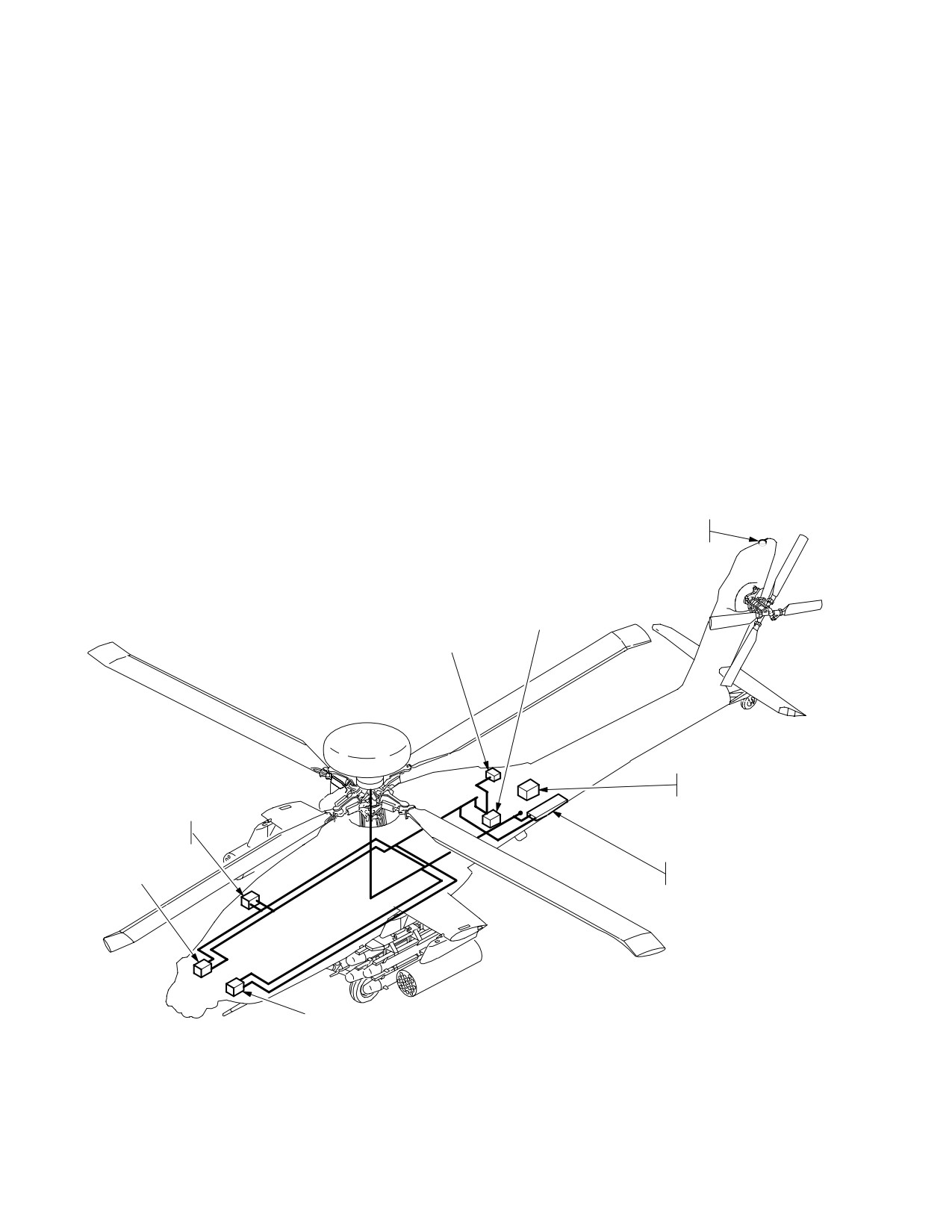
TM 1-1520-251-10
Section III. NAVIGATION SUBSYSTEM
3A.72 INTRODUCTION
2. Doppler Radar Velocity Sensor (DRVS).
This section describes crew interface requirements for
3. Air Data System (ADS).
management of the navigation subsystem (fig. 3A-90).
The navigation subsystem provides aircraft heading, atti-
4. Radar Altimeter (RAD ALT).
tude, Present Position (PP), velocity (relative to ground
and air), radar and barometric altitude, and distance in-
5. Automatic Direction Finder (ADF).
formation for piloting and navigating. The navigation sub-
system consists of the following major components:
6. High Integrated Air Data Computer (HIADC).
1. Embedded Global Positioning System Inertial
Navigation System (EGI).
7. Flight Management Computer (FMC).
GPS
ANTENNA
HIADC
ADF
RECEIVER
RADAR
ALTIMETER
FLIGHT MANAGEMENT
COMPUTER
DOPPLER RADAR
EGI 2
VELOCITY SENSOR
EGI 1
LBA2400
Figure 3A-90. Navigation Subsystem
Use or disclosure of this information is subject to the restriction(s) on the title page of this document.
3A-102
Change 4
TM 1-1520-251-10
3A.73 EMBEDDED GLOBAL POSITIONING SYSTEM
prompting the aircrew for input for the respective EGI and
INERTIAL NAVIGATION SYSTEM (EGI)
doppler boresight numbers.
The aircraft has two EGIs which use internal accelerome-
Once the EGIs have been provided the boresight num-
ters, rate gyro measurements, and external sensor mea-
bers and the NAV mode, the EGIs will determine the air-
surements to estimate the aircraft state. Only one EGI
craft attitude. Upon finding attitude (i.e. attitude displayed
provides aircraft state information to aircraft systems
on the FLT page), the NAV system will provide the EGIs
while the second EGI is for backup. The external sensor
with position information from the primary EGIs GPS (if
measurements include range and range rate from the
tracking satellites) or the NAV system’s last stored posi-
GPS, velocity from the DRVS, barometric altitude, and
tion at power down.
manual position updates from the system processor (SP).
Incorporated within the EGI is an Inertial Measurement
If no GPS or last stored present position is available, the
Unit (IMU) and the processing functions for performing the
NAV system will provide an advisory prompt on the EUFD
inertial navigation computations, GPS navigation solu-
directing the crew to enter a present position. If a GPS
tions, receiver management, and Kalman filter estimates
position is given to the EGIs to align to, the EGIs initial
to support all aircraft and weapon systems requirements.
position confidence on the TSD UTIL page will read
approximately .031 km. If a stored position is given to the
The data derived from the EGI includes :
EGIs to align to, the EGI initial position confidence on the
TSD UTIL page will read approximately 9.00 km. When a
• Acceleration
position is manually entered to the EGIs to align to on the
• Angular rate
ground, the EGI initial position confidence on the TSD
UTIL page will read approximately .050 km.
• Attitude
• Heading
Upon the EGIs being given a present position, the NAV
• Velocity
system will provide an alignment command to the EGIs.
The EGIs alignment time is approximately 4 minutes on
• Position
the ground. When an in-flight alignment is performed by
• Position Error Estimate
an INU reset the alignment time, with GPS tracking satel-
lites with crypto keys verified and doppler velocities avail-
a. System Description. The EGI is a velocity
able, is approximately 35 seconds. If an in-flight alignment
aided, strapdown, ring laser gyro based inertial unit. The
is performed with doppler velocity aiding only (no GPS),
EGI unit also houses the 5 - channel GPS receiver.
the alignment time is approximately 6 minutes.
b. Operation. Initialization and alignment of the EGI
The heading tape symbology is displayed and TSD Map
is automatically controlled by the primary System Proces-
Frozen Cue is removed when alignment of the primary
sor (SP) upon generator power up of the aircraft. Upon
EGI is complete. The reaching of alignment of the second-
power up, the SP provides the boresight numbers stored
ary EGI is noted by the removal of the inhibit selection bar
in non-volatile memory, for each EGI and doppler, and the
beside the primary INU selection on the TSD UTIL page.
last NAV mode stored (i.e. Land or Sea) at power down of
There is no effect on the NAV system accuracy if the en-
the aircraft. If no boresight numbers have been stored, the
gines are started, or if the main rotor is turning during
NAV system will provide an advisory on the EUFD,
alignment.
Use or disclosure of this information is subject to the restriction(s) on the title page of this document.
Change 2
3A-103
TM 1-1520-251-10
3A.73.1 Global Positioning System (GPS).
3A.73.2 Map Datums. Map datums are mathematical
models of the Earth used to calculate the coordinates on
a. System Description. The GPS receiver installed in
maps and charts. Currently, many datums are used through-
each EGI is a 5-channel receiver. The receiver is capable of
out the world to produce maps. The standard for US Forces
operating in either C/A code or encrypted P/Y code. The
is World Geodetic System 1984 (WGS 84). However, many
Group User Variable (GUV) is the normal encryption key
US Military Grid Reference System (MGRS) and foreign
used. The GUV key is loaded into the EGI using a fill device.
maps are still based on other datums. Not correcting for dif-
When keyed the GPS receiver will automatically use anti-
ferent datums can cause significant errors. The coordinates
spoof/jam capabilities when they are in use. The EGI keying
for a point on the Earth’s surface in one datum will not match
connector is located in the aft avionics bay on the multifill port
the coordinates from another datum for the same point. The
panel. The EGI will retain the key through power ON/OFF/ON
Navigation System requires that the datum be entered with
cycles. Because of safeguards built into the EGI, it is not con-
the coordinate data. If it is not entered, it will default to the
sidered classified when keyed. The antenna for the GPS re-
present position datum. The datum included with each set of
ceiver is located on the top of the vertical stabilizer.
coordinate data allows the Navigation System to calculate the
NOTE
compensations for different datums. The datum used is iden-
The GPS signal is vulnerable to jamming and
tified by a two digit number. Table 3A-6 lists all of the datums
spoofing operations. Under these conditions
that may be used with the Navigation System.
some or all satellites may be unboxed and/or
Table 3A-6. Datum Names and Codes
aircraft position, airspeed and/or position confi-
Datum Code Used
dence may be excessively high or changing
Datum
By Navigation
quickly.
Name/Description
System
b. Operation. The operation of the GPS receiver is en-
Adindan
01
tirely automatic. The GPS receiver is powered when the EGI
ARC 1950
02
is powered. If the GPS is keyed, it may take as long as 12
Australian 66
03
minutes to verify the key with the satellites. The GPS pro-
vides range and range rate information to the EGI as well as
Bukit Rimpah: Indonesia
04
position and time information to the System Processor (SP).
Camp Area Astro
05
When the GPS has tracked the first satellite, it will update the
Djarkarta: Indonesia
06
date and time to the Navigation System. There are no specif-
European 1950
07
ic operator actions that may be taken with the GPS system.
Geodetic Datum 1949
08
c. Data Transfer Unit (DTU). The DTU is used to load
Ghana
09
mission data, digital maps, and images into the aircraft. The
Guam 1963
10
data is transferred by the DTU from the Data Transfer Card
Gunung Segara: Indonesia
11
(DTC). The DTC is programmed using the Aviation Mission
Gunung Serindung: Indonesia
12
Planning System (AMPS). The AMPS writes the coordinate
Herat North
13
files for waypoints, control measures, hazards, targets,
Hjorsey
14
threats, and routes with their associated waypoints. The NAV
Hu-Tzu-Shan
15
mode and present position for the EGI’s can be loaded from
the DTC. Whenever the pilot or CPG makes changes to any
Indian: Mean Value For Thailand
16
of the waypoints or routes, the SP will automatically update
And Viet-Nam
the DTC with those changes. The SP will preserve those
Ireland 1965
17
changes in the event of an electrical power transient.
Kertau: West Malaysia
18
Liberia 1964
19
Local Astro
20
Luzon
21
Merchich
22
Montjong Lowe: Indonesia
23
Minna
24
North American Datum of 1927:
25
Continental US
Use or disclosure of this information is subject to the restriction(s) on the title page of this document.
3A-104
Change 3
TM 1-1520-251-10
Table 3A-6. |Datum Names and Codes (cont)
NOTE
Datum Code Used
If the aircraft has been moved over one nauti-
Datum
By Navigation
cal mile since it’s last power down (LAT/LONG
Name/Description
System
data differs more than one minute from actual
position) and does not acquire satellites within
North American Datum of 1927
26
a short time (three-five minutes) after power
Alaska: Canada
up, the following procedures will help insure a
Old Hawaii: Maui
27
good alignment.
Old Hawaii: Oahu
28
a. Aircraft Moved Over One Nautical Mile Since
Old Hawaii: Kauai
29
Last power Down.
England Scotland Wales
30
(1) Manual Procedure.
Qornoq
31
(a) Ensure that the current Zulu date and time
Sierra Leone 1960
32
are entered on the TSD UTIL page.
Campo Inchauspe: Argentina
33
(b) Check the left side of the TSD page to see if
Chua Astro: Paraguay
34
the HDG selection is displayed. If so, select PSN and enter
Corrego Alegre: Brazil
35
the aircraft current position. (The HDG selection must be dis-
Provisional South American 1956
36
played when entering the current position.) If HDG is not dis-
Yacare: Uruguay
37
played or the HDG selection is removed while the current
Tananarive Observatory: South
38
position data is being entered, perform an INU1 and INU2 re-
American 1925
set and then quickly (within one minute) enter the aircraft cur-
rent position.
Timbali: East Malaysia
39
Tokyo: Japan: Korea: Okinawa
40
(2) DTU Procedure.
Carthage
41
(a) If the correct aircraft current position has
Special Datum: Indian Special
42
been entered on the DTU, selecting Navigation on the DTU
page will automatically update the current stored position and
Special Datum: Luzon
43
reset the EGI(s) if the Position Confidence (PC) values are
Tokyo Special
44
greater than 0.031 km.
WGS 84 Special Datum
45
b. EGI Position Updates (GPS and/or Doppler Aid-
WGS 72 (Sino-Soviet Bloc)
46
ing Not Available).
WGS 84 Standard Datum*
47
(1) EGI position updates can be accomplished
*All FAA Sectionals and FLIP use this datum for coordi-
anytime the PSN selection on the TSD page is present
nate data.
(Primary EGI Position Confidence value greater than
0.050 km).
3A.73.3 EGI Operational Procedures.
(2) If the position is not updated before the Position
Confidence factor increases to approximately 0.10 km the
EGI(s) may not apply the full correction to present position. In
CAUTION
cases like this, several position updates may be required to
minimize the differences between EGIs position and actual
position. If the confidence factor gets too high, the EGIs may
The GPS system may provide erroneous
reject all position updates. If this is the case, the aircraft will
system data during normal GPS operations
need to land, crew perform an INU1 and INU2 reset followed
due to signal jamming and spoofing opera-
by an immediate present position update to align the EGIs.
tions. Verify proper EGI operation using the
3A.74 AN/ASN-157 DOPPLER RADAR VELOCITY
TSD UTIL page, position checks, and atti-
SENSOR (DRVS)
tude display against external references
The aircraft contains one DRVS, which consists of a re-
and back-up instruments. If jamming or
ceiver/transmitter, antenna, signal data converter comput-
spoofing is suspected, perform position
er, and a 1553B interface, all combined in one unit. The
updates. Position updates will temporarily
DRVS provides aircraft referenced ground velocities to
delay erroneous position errors only.
both EGIs as a velocity aiding source.
Use or disclosure of this information is subject to the restriction(s) on the title page of this document.
Change 3
3A-105
TM 1-1520-251-10
3A.75 AIR DATA SYSTEM (ADS)
3A.76 AN/APN-209 RADAR ALTIMETER (RADALT)
The aircraft contains one Radar Altimeter. The Radar Altime-
The ADS is comprised of two independent air data subsys-
ter consists of a receiver/transmitter and antennas which pro-
tems. The Flight Management Computer (FMC) comprises
vides actual terrain clearance height. The information is dis-
the first air data subsystem, and the Helicopter Air Data Sys-
played on the MPD and Helmet Display Unit (HDU) and
tem (HADS) comprises the second air data subsystem.
presented in audio format via the CIU for low altitude excee-
dances only.
3A.75.1 Helicopter Air Data System (HADS). The HADS
is comprised of a High Integrated Air Data Computer
Together the ADS and the Radar Altimeter provide the in-
(HIADC), two Airspeed and Direction Sensors (AADS)
formation necessary to display mean sea level (MSL) ter-
probes, a Selector Valve Assembly (SVA), and a Utility Relay
rain elevation for the aircraft present position under cer-
Box (URB). The AADS probe senses airspeed magnitude,
tain valid data parameters.
direction, and free airstream temperature. The AADS probe
3A.77 AN/ARN-149 AUTOMATIC DIRECTION FINDER
interfaces indirectly through the SVA and URB to the HIADC.
(ADF)
The right AADS probe temperature sensor is the only probe
The ADF receives frequencies from 100 to 2199.5 khz.
to provide temperature information directly to the SP. The left
The ADF has two functional modes of operation: ANT and
AADS probe temperature sensor is not used. The SP con-
ADF. In ANT mode the ADF functions as an audio receiver
trols the selection of which AADS probe provides information
providing only an audio output of the received signal. In
to the HIADC, based on status information from the HIADC.
ADF mode it functions as an automatic direction finder
The HIADC contains the processor and related hardware,
system that provides a relative bearing to the station sig-
along with ambient and pitot pressure sensors, to compute
nal as well as an audio output of the received signal.
air mass related data.
3A.78 NAVIGATION SUBSYSTEM CONTROLS AND
3A.75.2 FMC. The FMC air data subsystem also contains
DISPLAYS
the processor and related hardware to compute pressure alti-
Navigation subsystem controls and displays are inte-
tude, pitot airspeed and density altitude related information.
grated into the following major components:
The FMC receives longitudinal and lateral True Air Speeds,
• Multipurpose Displays (MPD)
static temperature, and longitudinal and lateral True Air
• Keyboard Unit (KU)
Speed non-filtered indirectly from the HIADC via the SP. The
• Enhanced Up Front Display (EUFD)
FMC outputs, via the MUX bus, a common airdata message
of the received HIADC and derived FMC airdata information
The TSD frame of reference is relative to one of three select-
to those onboard aircraft subsystems requiring it. The FMC
able orientations on the MAP page; north-up, track-up, or
provides the following data:
heading-up. In the PAN mode, the TSD frame of reference is
determined by the PAN controls. The TSD uses graphic sym-
• Pressure Altitude
bols to illustrate waypoints and routes, hazards, phase lines,
• Density Altitude
targets/threats, and various control measures. The KU can
• Barometric Altitude
be used to enter information when required. The NAV system
• Static Air Pressure
provides, on the EUFD, advisories for waypoint approach
and passage, entry of EGI boresight data, and position up-
• Sideslip Angle
date.
• Lateral True Air Speed
3A.79 MPD TACTICAL SITUATION DISPLAY (TSD)
• True Air Speed
The TSD page, (fig 3A-91) controls navigation subsystem
• Calibrated Air Speed
moding. Selecting the TSD subsystem button or the TSD but-
• Longitudinal True Air Speed
ton from the MENU page calls up the TSD page which inte-
• Static Temperature
grates various navigation status windows, graphic symbols,
• Air Density Ratio
digital maps, and control selections.
Use or disclosure of this information is subject to the restriction(s) on the title page of this document.
3A-106
Change 2
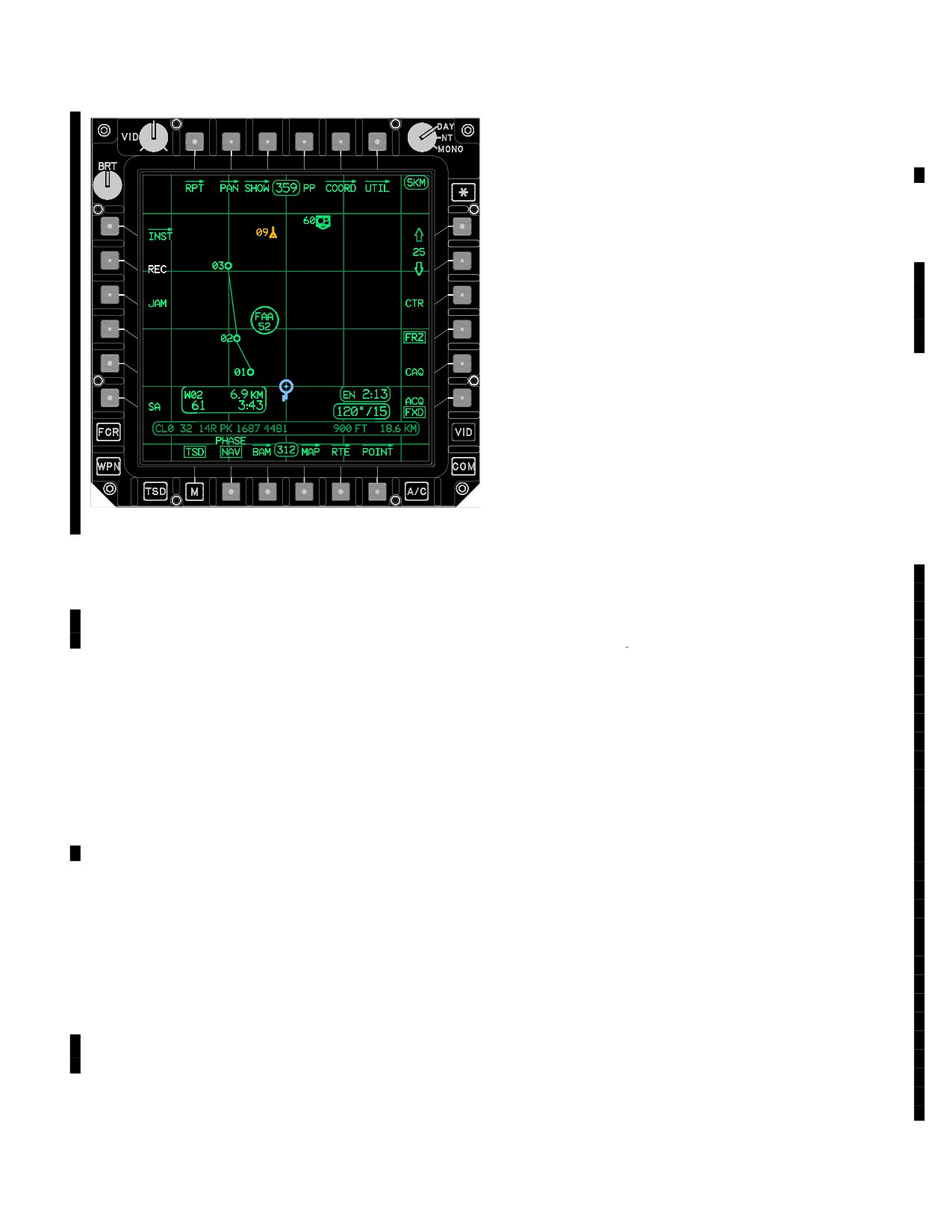
TM 1-1520-251-10
3A.79.1 TSD Map Functionality. The TSD can be con-
figured for 2 different phases of the mission. The NAV
phase provides enroute information and the, ATK phase
provides information pertaining to the battle area.
3A.79.2 RPT Page Button. Selection of the RPT but-
ton will cause the RPT page to be displayed.
3A.79.3 PAN Page Button. Selection of the PAN but-
ton will cause the PAN page to be displayed.
3A.79.4 SHOW Page Button. Selection of the SHOW
Page button will cause the SHOW page to be displayed.
3A.79.5 Present Position (PP) Button. Selecting the
PP button commands display of the present position sta-
tus window.
3A.79.6 COORD Page Button. Selection of the COORD
button will cause the COORD page to be displayed.
3A.79.7 TSD UTIL Button. Selection of the UTIL but-
LBA5063A
ton will cause the UTIL page to be displayed.
Figure 3A-91. TSD Page
3A.79.8 Map Viewing Range UP Button. The map view-
• T1
RPT Page button
ing range buttons (R1 & R2) are used to change the range (in
KM or NM) of the map on the screen in the 2D mode and the
• T2
PAN Page Page button
field of view (in degrees) in the 3D mode. The number be-
• T3
SHOW Page button
tween the arrows indicates the height and width (in kilometers
• T4
PP button
or nautical miles as selected on the FLT page) in the 2D map
mode and in degrees of field of view in the 3D map mode.
• T5
COORD Page button
Selection of the Arrow Up button causes more map to be
• T6
UTIL Page button
displayed (changing the 2D zoom and/or scale or the 3D field
• L1
INST Page button
of view of the map as necessary). If the button is selected
• L2
REC button
and released, the next higher default map viewing range or
field of view option will be selected. If selected and held, the
• L3
JAM button
map will continuously zoom out. For a brief time afterwards
• L5
HDG button
the number will be bolded, indicating selection of the Arrow
• L6
PSN button
UP will fine tune the map viewing range or field of view. The
• L6
SA button
default Map viewing ranges for the
2D map are:
400K/216NM, 150K/81NM, 100K/54NM, 75K/40.5NM,
• R1
Map Viewing Range UP button
50K/27NM,
25K/13.5NM,
15K/8.1NM,
10K/5.4NM,
• R2
Map Viewing Range DOWN button
5K/2.7NM, 2K/1.1NM and 1K/.5NM. The default Map fields of
• R3
CTR button
view for 3D map are: 15, 30, 45, 60, 75, and 90 degrees.
• R4
FRZ button
3A.79.9 Map Viewing Range DOWN Button. Selection of
• R5
CAQ (Cursor Acquisition) button
the Arrow Down button causes less map to be displayed
• R6
ACQ button
(changing the 2D zoom and/or scale of the 3D field of view of
• B2
PHASE button
the map as necessary). If the button is selected and released,
the next lower default map viewing range or field of view op-
• B3
BAM Page button
tion button will be selected. If selected and held, the map will
• B4
MAP page button
continuously zoom in. For a brief time afterwards the number
• B5
RTE Page button
will be bolded, indicating selection of the Arrow down will fine
• B6
POINT Page button
tune the map viewing range or field of view.
Use or disclosure of this information is subject to the restriction(s) on the title page of this document.
Change 3
3A-107
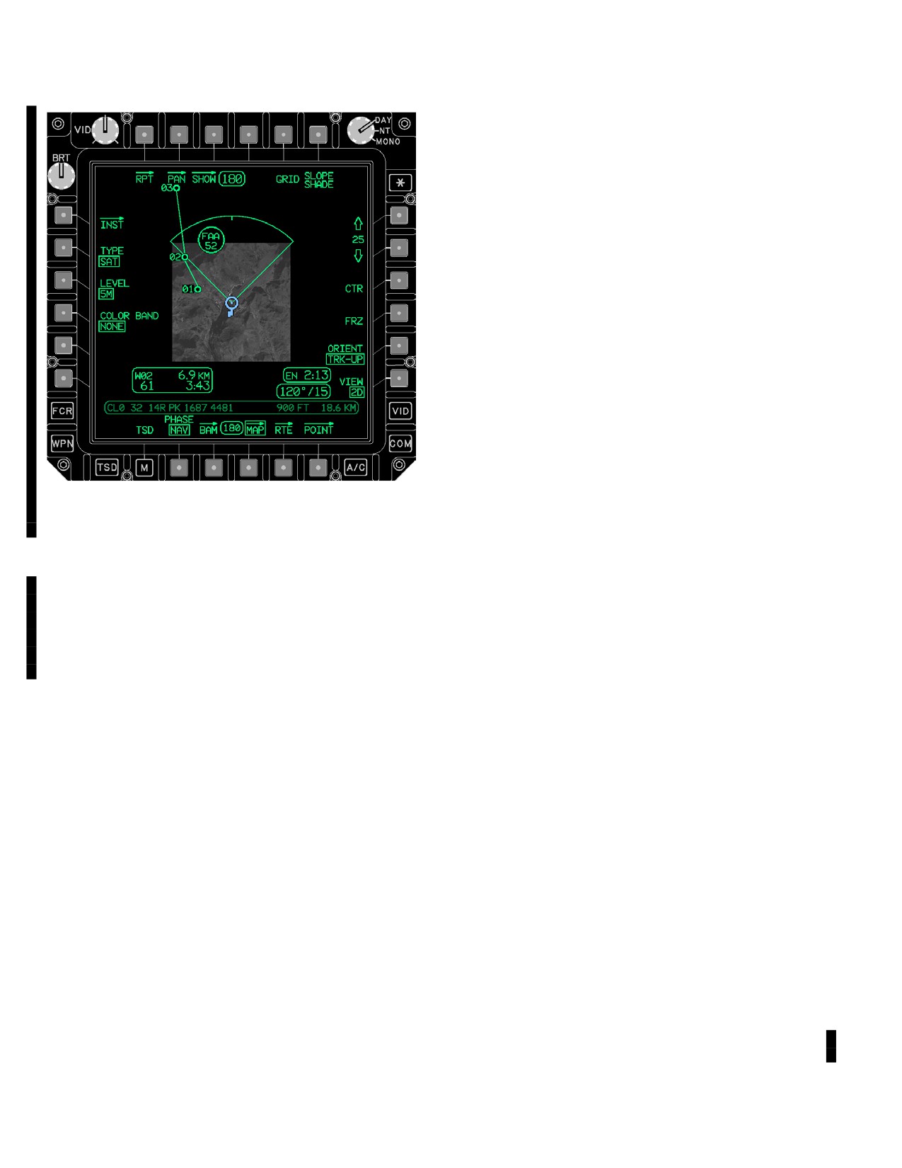
TM 1-1520-251-10
With CAQ selected, the crewmember’s cursor is active for
selecting a terrain point on the TSD. When the crewmember
does not select a point on the TSD the TRN (terrain) “cross”
symbol is displayed with the label PLT or CPG. The TRN
symbol is white. The geographic location is stored in coordi-
nate COORD file T55 for the pilot and T56 for the CPG. If
each crewmember has a point selected, two TRN symbols
with the appropriate crewstation label will be displayed on the
TSD. RFI detected threats are only selectable when the se-
lected sight is TADS or Helmet Mounted Display (HMD).
Selecting the CAQ button freezes the TSD map.
3A.79.13 Acquisition (ACQ) Button. The ACQ button
provides the ability to select the desired acquisition
source for the selected sight. See Chapter 4 for descrip-
tion of selections.
3A.79.14 INST Page Button. Selection of the INST
button will cause the INST page to be displayed.
3A.79.15 Receive (REC) Button. The REC button is used
to receive the most recent IDM messages that can be re-
ceived from the TSD page. The REC button is only displayed
LBA5257
when a message is in the IDM buffer. The REC button is dis-
Figure
3A-91A.
MAP Viewing Range (Extended)
played in WHITE. When the REC button is selected by a
single push, the received grouped options are displayed with
NOTE
up to four IDM messages (IDM sender callsign) displayed.
Selection of an IDM callsign will store the message to the cur-
Certain maps can be zoomed out further than
rent mission or automatically switch to the RCVD message
the viewable limits of the map in order to show
the entire FCR footprint when the ownship is
page for TACFIRE messages. When the REC button is se-
centered on the display. (The 12.5K Scale
lected by a double push, the last message received will be
maps can only be zoomed to show the entire
stored. When the selected message is one of the following,
footprint when the ownship is decentered.)
the message will be stored in the appropriate current mission
file location without being identified:
3A.79.10 Center (CTR) Button. Selecting the CTR button
toggles the ownship symbol to the center or aft section of the
• WPT/HZD
map area (based on orientation selection) on the display.
• CTRLM
3A.79.11 Freeze (FRZ) Button. Selection of the FRZ
• TGT/THRT
button provides the ability to freeze the map display or re-
• FCR TGT RPT
turn to an active display.
• BDA REPORT
3A.79.12 Cursor Acquisition (CAQ) Button. The CAQ
• PF ZONE
button allows for rapid selection of points/icons on the TSD
to set as an acquisition source. When the CAQ button is se-
• NF ZONE
lected the crewmembers can use the cursor to select any of
• PF/NF ZONE
the following on the TSD page for use as acquisition source:
• RFHO
• Waypoints, Hazards, Control Measures
• PP REPORT
• Pre - planned or Stored Targets/Threats
• FARM REPORT
• FCR Detected Targets
When the message received is one of the following, se-
• RFI Detected Targets
lecting the IDM callsign will automatically switch to the
• A Terrain TRN location on the TSD selected using
RCVD MSG page of the ATHS-TACFIRE. See figure
the cursor
3A-89A in paragraph 3A.71.6 for more information.
Use or disclosure of this information is subject to the restriction(s) on the title page of this document.
3A-108
Change 3
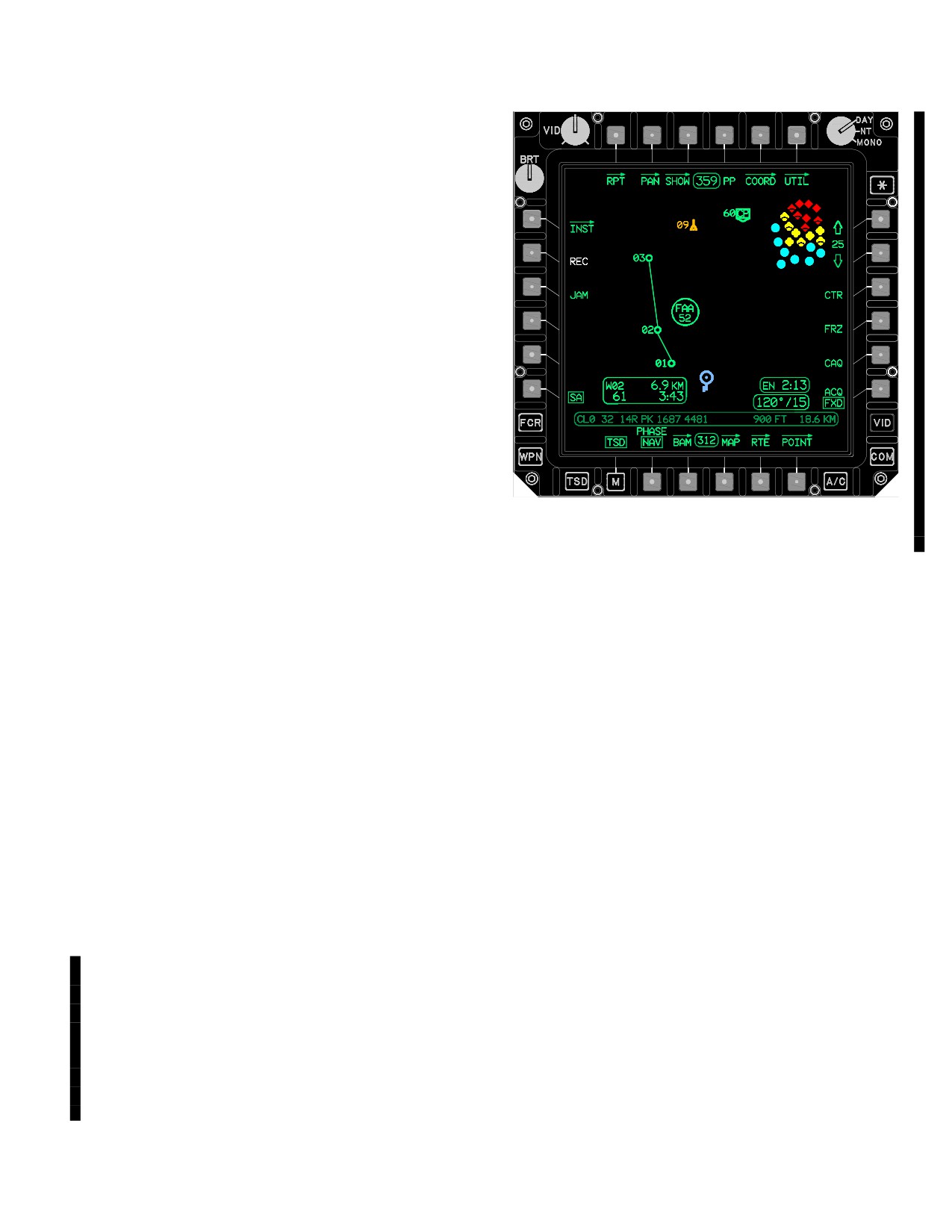
TM 1-1520-251-10
• FREE TEXT TAC
• BDA REPORT TAC
• FARM REPORT TAC
• PP QUERY TAC
• PP REPORT TAC
• MAYDAY REPORT TAC
• MOVE COMMAND TAC
• SPOT REPORT TAC
• NEG SPOT RPT TAC
• AIR FIRE RQST TAC
• ARTY INTELGRID TAC
• ARTY FIRE RQST TAC
LBA5243A
• MSG TO OBSERVER TAC
Figure 3A-91B. SA Selected On
• OBSERVER READY TAC
3A.79.18 Heading (HDG) Button. The system displays
the HDG button when the primary EGI estimated heading er-
When the message received is one of the following, se-
ror is greater than 10 degrees. The HDG button is displayed
lecting the IDM callsign will cause the appropriate symbol
in WHITE. Selecting the HDG button brings up the HEADING
to display on the TSD.
button which is used to enter a new heading.
a. HEADING Button. The HEADING button is used
• SPOT REPORT
to enter the correct aircraft heading through the KU. An UPT
button is displayed when the new heading has been entered.
• SITREP
b. Heading Update (UPT) Button. The UPT button
• AIR FIRE MISSION
is used to command the system to update both EGIs with
the aircraft heading entered with the HEADING button.
• MSG TO OBSERVER
3A.79.19 PSN Button.
The PSN button is displayed
• OBSERVER MSN UPDT
in WHITE. The system displays the PSN update button
when the estimated radial position error from the primary
3A.79.16 Radar Jammer (JAM) Button. This button is
EGI is greater than 50 meters (0.050 Km). Selecting PSN
only displayed when the jammer is turned ON. Selecting
will cause the POSITION button to be displayed.
the JAM button toggles the radar jammer between STBY
and OPER.
a. POSITION Button. The POSITION button is used
to enter the correct LAT/LONG or UTM coordinates through
NOTE
the KU. Selecting the POSITION button will arm the KU for
entry of the new coordinates. The system will accept LAT/
Situational Awareness (SA) information is pro-
LONG or UTM coordinate data, with or without the entry of
vided by the IDM. The aircraft must be logged
the datum. If a coordinate is entered without a datum, then
on to the TI in order to receive SA data.
the system assumes whatever the current datum being flown
is what the coordinate being entered is in. Rather than enter-
3A.79.17 Situational Awareness (SA) Button. See
ing the coordinates using the KU, the crew can also select
para 3A.87.3d and fig 3A-91B for a description of this but-
any coordinate point (waypoint, hazard, control measure, or
ton.
stored target/threat) using the cursor control. The system
Use or disclosure of this information is subject to the restriction(s) on the title page of this document.
Change 3
3A-109
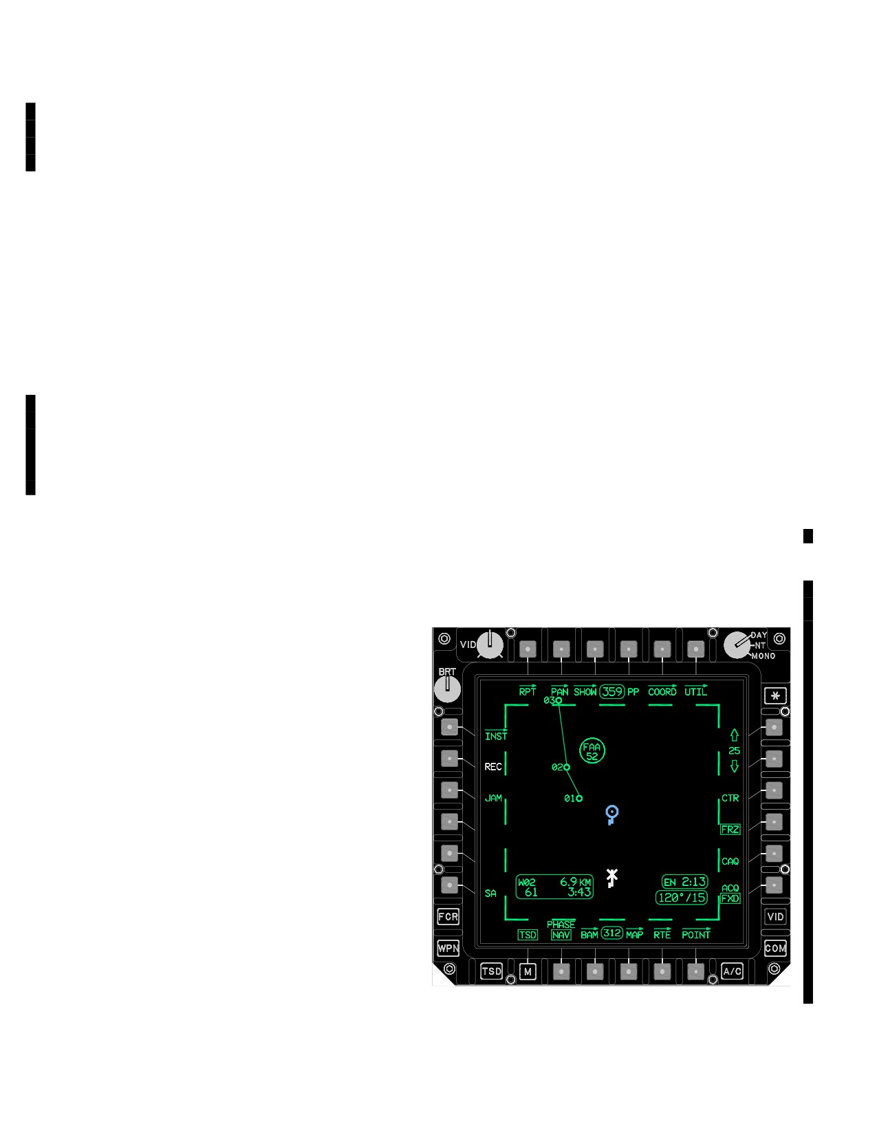
TM 1-1520-251-10
loads the UTM coordinates for the selected point. If a coordi-
3A.79.26 Aircraft Heading Status Window. The air-
nate point is not selected, the cursor can be used to pick any-
craft heading status window is displayed at the top center
where on the map. The system loads the UTM coordinates of
of the format.
that location. A UPT button is displayed when the new coordi-
nates have been entered.
3A.79.27 Grid Status Window. The grid status is dis-
played in the upper right corner of the format when GRID
b. Position Update (UPT) Button. The UPT but-
is selected from the MAP page. The status window shows
ton is used to command the EGIs to update their present
the distance (in KM or NM as selected via the FLT SET
position with the new coordinates entered using the POSI-
page) between the grid lines.
TION button.
3A.79.28 Map Frozen Cue. The TSD map frozen cue
3A.79.20 PHASE Button. The PHASE button allows
(fig 3A-92) is a bold dashed and a frozen ownship symbol
the crew to select either NAV (Navigation) or ATK (Attack)
at the centered/ decentered location, to indicate the map
mode of operation. The mode of operation affects which
is not in a dynamic state. The dynamic ownship (CYAN),
information is presented on the TSD page and which op-
TADS footprint, and FCR footprint will continue to move
tions are available on the SHOW page.
about the viewable area, and the heading and waypoint
information will provide continuous real - time situational
3A.79.21 Battle Area Management (BAM) Page But-
awareness. The following control selections cause the
ton. Selection of the BAM button will cause the battle
map to freeze:
area management page to be displayed.
•
BAM page button
3A.79.22 MAP Button. Selection of the MAP button
• CAQ button
will cause the MAP page to be displayed.
• FRZ button
3A.79.23 Route (RTE) Page Button. Selection of the
RTE button will cause the route page to be displayed.
• PAN buttons
NOTE
3A.79.24 Point (POINT) Page Button. Selection of the
POINT button will cause the point page to be displayed.
TSD Map Frozen Cue is in place until Prima-
ry EGI alignment is complete.
3A.79.25 Next Waypoint Status Window. The next
WAYPOINT status window is displayed in the lower left
area of the MPD. It is displayed in the NAV mode to pro-
vide information regarding the current active waypoint be-
ing directly flown to or the current flight route being flown.
The status window includes the following:
a. Next Waypoint Letter and Number. The next
waypoint letter identifies the active destination point type,
which can be a waypoint “W”, hazard “H”, control measure
“C”, or a target/threat “T”. The next waypoint number will
be a number form 1 to 99 (depending on the point type).
b. Distance To Go. The distance to go will be dis-
played in either kilometers or nautical miles based on the
unit setting on the FLT SET Page.
c. Time To Go. The time to go will display either
minutes and seconds if the time is <5 minutes, or hours
and minutes if the time is >5 minutes and >10 hours.
LBA5062A
d. Ground Speed. If the current calculated ground
speed is valid, it will be displayed in kts.
Figure 3A-92. TSD Map Frozen Cue
Use or disclosure of this information is subject to the restriction(s) on the title page of this document.
3A-110
Change 3
TM 1-1520-251-10
3A.79.29 Next Waypoint Heading Status Win-
3A.79.33 Message to Observer Status Window. The
dow. The next waypoint heading status window is dis-
message to observer status window is displayed in the
played at the bottom center of the format.
center right of the format of the TSD, RPT, ARTY, and AF
pages, and can be displayed or removed from display via
3A.79.30 Cursor Location Status Window. The cursor
cursor or button selection. The status window is not
location status window is displayed in the lower center of the
enabled for display when a check fire-target or check
format. The status window displays the cursor position in
fire - all condition is in effect.
UTM. If UTM is not valid, LAT/LONG coordinates will be
used. As the aircraft moves or as the cursor is moved over
the TSD map the cursor position will update and indicate the
3A.79.34 Spot Report Status Window. The spot report
cursor position’s MSL Altitude of the terrain if DTED is avail-
status window is displayed in the upper portion of the format
able for that area. If DTED is not available, the altitude will be
of the TSD, RPT, and ARTY pages. It can be displayed or
displayed as “?”. Range from the ownship is displayed in KM
removed from display via cursor or button selection.
or NM. If the distance is greater than 1000KM or 1000NM, a
“?” will be displayed. When the cursor is moved to an alter-
3A.79.35 Situation Report Status Window. The situ-
nate display, the cursor location status window will display the
ation report status window is displayed in the upper
last cursor position in partial intensity.
portion of the format of the TSD, RPT, ARTY, and AF
pages. It can be displayed or removed from display via
3A.79.31 Present Position Status Window. The pres-
cursor or button selection.
ent status window is displayed in the lower center of the
format when the PP button is selected. The status window
includes the following information:
3A.79.36 Airfire Mission Status Window. The airfire
mission status window is displayed in the upper portion of
• Latitude
the format of the TSD, RPT, ARTY, and AF pages, and
• Longitude
has the property that allows it to be displayed or removed
from display via cursor or button selection.
• UTM coordinate data
• Current Mean Sea Level (MSL) elevation of the
3A.79.37 Time of Flight Not Available Status
terrain below the aircraft
Window. The time of flight not available status window
is displayed in the upper right of the format of the TSD,
NOTE
RPT, ARTY, and AF pages. It is displayed in conjunction
The displayed TOF is initiated after select-
with display of the message to observer status window.
ing the REC button, however, actual TOF is
initiated when message is transmitted.
3A.79.38 Endurance Status Window. The EN status win-
3A.79.32 Observer
Mission
Update Status
dow is displayed in the lower right area of the format to indi-
Window. The observer mission update status window is
cate total fuel endurance time at the present power setting.
displayed in the upper right of the format of the TSD, RPT,
Calculations include fuel in internal, center, and auxiliary
ARTY, and AF pages. It is displayed or removed from display
tanks (if installed). The EN label is displayed in WHITE and
in conjunction with selection for display of the message to
flashes when the total fuel endurance is 20 minutes or less.
observer status window. It is not displayed when the time of
flight not available status window is presented. The status
3A.79.39 Check Fire All Status Window. The check
window is also displayed when projected time of flight for
fire all status window is displayed in the upper center of
artillery rounds indicates time to impact is between 1 and 30
the format of the TSD, RPT, ARTY, and AF pages. It is
seconds.
displayed when the check fire all condition exists.
Use or disclosure of this information is subject to the restriction(s) on the title page of this document.
Change 3
3A-111
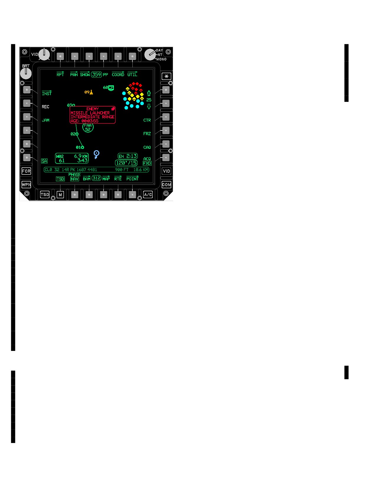
TM 1-1520-251-10
• Course and Speed
• UTM Coordinate data
• Latitude and Longitude
• Altitude (MSL in Feet)
3A.79.42 Engage Status Window. The engage status
window is displayed in the upper right of the format of the
ARTY page when all requirements have been satisfied to
allow transmission of an on - call request (OCR) message,
and no OCR has yet been issued. The status window is
also presented on the AF page during the conduct of a re-
mote SAL hellfire mission. It serves as a prompt that a
“SHOT” message has been transmitted and the target
should now be engaged.
3A.79.43 Compliance Request Status Window. The
compliance request status window is displayed in the upper
LBA5258
left corner of the format of the TSD, ARTY, and AF pages. It
is displayed when a compliance request has been issued
with a JVMF message that can be stored from the TSD,
Figure 3A-92A. SA Status Window, Small
ARTY or AF page. COMPLY REQ status window will be dis-
played on the TSD page after receipt of the message if a
3A.79.40 SA Status Window, Small. The small SA
compliance is required. Response to a compliance request
status window (fig 3A-92A) is displayed in the center of
must be initiated via the MSG REC page
the format of the TSD page. It is displayed when a SA icon
is selected. The small SA status window provides infor-
3A.79.44 Wind Direction/Velocity Status Win-
mation about the selected icon. The small SA status
dow. Wind direction and velocity is selectively displayed in
window frame and text are color coded to match the se-
the NAV and ATK phases, in the lower right corner of the
lected icon. The status window includes the following in-
TSD. If wind speed is less than 5 knots, the label CALM is
formation:
displayed. When Nr is less than 50% and wind speed is
greater than 45 knots, wind speed is displayed in YELLOW.
• Friendly, Enemy, or Unknown
3A.80 TSD MAP SYMBOLOGY
• Type
The following paragraphs describe various symbols and
the conditions under which they appear within the TSD
• Subtype
map area. The symbols are displayed in geographic fidel-
• Age (how old the information is)
ity according to the map scale selected. The display of any
particular symbol depends upon the PHASE selection
• Unit ID or URN
and the state of the control selections on the SHOW page.
Also, symbols cannot be displayed on a 3D map. See
3A.79.41 SA Status Window, Large. The large SA
para 3A.87.1, 3A.87.2 and 3A.82.2.
status window is displayed in the center of the format of
the TSD page. It is displayed when the expand icon on a
3A.80.1 Ownship Symbols. The dynamic ownship sym-
small SA status window is selected. The large SA status
bol is displayed in CYAN and represents the helicopter posi-
window provides additional information about the selected
tion within the dynamic mapping area. Specifically, the dot in
icon. In addition to the information included in the small
the center of the ownship symbol depicts the present position
SA status window. The large SA status window frame and
of the helicopter relative to the map symbols. The frozen
text are also color coded to match the additional selected
ownship symbol is displayed in WHITE, with stopped rotors,
icon. The large status window contains the following infor-
and remains at the centered or decentered position as se-
mation:
lected.
Use or disclosure of this information is subject to the restriction(s) on the title page of this document.
3A-112
Change 3
TM 1-1520-251-10
3A.80.2 Route Line. The route line is a straight line
d. When on the POINT page with the ADD, EDIT,
connecting the points (waypoints, hazards, and control
DEL, or XMIT button selected and the waypoint/hazard is
measures) in the current route. The route line becomes
currently the active waypoint/hazard.
partial intensity when the active destination point is other
The valid range for the waypoint/hazard numbers is 1 to
than the next point in the current route.
50. There are 6 different waypoint symbols and 4 hazard
symbols that can be displayed on the TSD (App D). Haz-
3A.80.3 Direct-To Line. The route direct-to line is a
ards on the TSD page are always displayed in both
straight line indicating a direct course to the selected point.
phases. Waypoint symbols are always displayed in the
NAV phase and may be displayed in the ATK phase if
CURRENT ROUTE is selected. When the waypoint/haz-
3A.80.4 Grid Lines. Grid lines are displayed when grid is
ard files are loaded from the DTC, a number is stored for
selected on the MAP page. Grid lines are the default for all
each data file saved that indicates the “SAFE SET” for that
maps except CHART 1:50,000 and 1:100,000. The ownship
loaded DTC file (maximum of 25 points). This prevents
is the origin of the grid (except in North-Up/de-centered).
overwriting a ”SAFE SET” file via normal storing proce-
The grid lines are displayed in partial intensity green when no
dures. Data can be deleted from SAFE SET via the DEL
video underlay or map underlay is displayed. If video or map
button or changed from within the ownship via the EDT
underlay is present, grid lines are displayed in black.
button. An incoming IDM message, if elected to be stored,
can also overwrite a SAFE SET. For example: If 10 way-
3A.80.5 Waypoint/Hazard (WPTHZ) Icon. A WPTHZ
points/hazards are loaded through the DTC, and then
icon indicates the location, type and number of a waypoint
point number 11 is stored after DTC loading, the SP will
or hazard stored in the waypoint/hazard coordinate data
not attempt to store a waypoint/hazard with an index less
files. Hazard icons are displayed in YELLOW. The way-
than 11. If the DP requests to store a point with an index of
point/hazard number is displayed to the left of the way-
less than 11, then the SP will do this.
point or hazard symbol. The waypoint/hazard number will
3A.80.6 Control Measure (CTRLM) Icon. A CTRLM
be displayed inverse video when any of the following
icon indicates the location, type and number of a control
conditions exist:
measure stored in the coordinate data files. Friendly control
measure icons are displayed in CYAN and enemy control
a. When on the RTE page with the ADD button se-
measure icons are displayed in RED. The control measure
lected and the waypoint/hazard is the currently selected
type and number is usually displayed within the CTRLM icon.
waypoint/hazard.
The point number will be displayed in inverse video when the
point is the currently selected or active point. The control
b. When on the RTE page and the waypoint/hazard is
measure file is made up of 49 points. The valid range for the
the currently selected waypoint/hazard.
point numbers is 51 to 99. Present position responses are
c. When on the POINT page and the waypoint/hazard
stored in C93 through C99 and are displayed on the TSD
is currently the active waypoint/hazard.
with the helicopter icon. (Appx D).
Use or disclosure of this information is subject to the restriction(s) on the title page of this document.
Change 3
3A-112.1/(3A-112.2 blank)
TM 1-1520-251-10
3A.80.7 Threat/Target (THRT/TGT) Icon. The THRT/
data files. The designated label indicates the type of LINE
TGT icon indicates the location/number of a target or the
icon.
location/type of a threat stored in the coordinate data files.
THRT/TGT icons are displayed in RED. When the THRT/
3A.80.11 AREA Icon. The AREA icon indicates the
TGT icon is a stored target, the icon is a T followed by the
boundary location, label, and number of a target engage-
target file number. When the THRT/TGT icon is a pre-
ment area stored in the coordinate data files. The engage-
planed target/threat, the icon may be a symbol with a 2
ment area label/number (EA##) of the AREA icon is at the
digit identifier. The target/threat number will be displayed
center point of the geographic area.
inverse video when the threat has been selected on the
POINT page in the RVW, EDIT, DEL or XMIT modes.
3A.80.12 ASE Footprint Symbol. The ASE footprint
symbol is a square border providing a perimeter line or
The valid range for the target/threat numbers is 1 to 56 The
footprint which segregates RLWR (inside) and RFI (out-
FCR target coordinate data is stored in T50 when the CAQ
side) threat symbols. It is automatically displayed on the
button is used to select an FCR target symbol. The coordi-
TSD page when a threat is detected by the RLWR.
nate data for the ATHS air fire mission target is stored in
T51. The JVMF call for fire target grid location is stored in
3A.80.13 TADS Footprint Symbol. The TADS footprint
T52. The JVMF Air Fire Mission target is stored in T53.The
symbol is a GREEN straight line which originates at the
JVMF spot report is stored in T54. The Pilot’s terrain ac-
ownship symbol and changes in length and azimuth to indi-
quisition source is stored in T55 and the Copilot’s in T56.
cate TADS LOS positioning within the map area. The
Targets over 50 do not exist on the DTC and are not trans-
GREEN line changes to a WHITE line when TADS is lasing.
mitted in any of the AFAPD messages. Targets over 50 can-
An open center crosshair symbol displays full intensity at the
not be edited nor can new targets be added/stored into tar-
end of the TADS footprint symbol to provide precise position
gets over 50 via the POINT page. The T51 ATHS TARGET
feedback on the map. The TADS footprint symbol displays
can be deleted when the HFMSN button is not selected.
when TADS is the selected sight for the CPG or either crew-
The SAFE SET also applies to the targets/threats file.
member has linked TADS to his current selected sight.
3A.80.8 ATHS TARGET Icon. The ATHS TARGET
icon is a large octagonal white icon. The ATHS TARGET
3A.80.14 FCR Footprint Symbol. The FCR footprint
icon is displayed around T51 when HFMSN is selected.
symbol is a perimeter of GREEN lines which originates at
the ownship symbol to indicate the FCR scan footprint or
3A.80.9 Message to Observer Symbol. The message
FCR scan azimuth and area of coverage within the map
to observer symbol (fig 3A-93) is a large circular white icon
area. The GREEN lines change to WHITE lines when the
with protruding edges. The large symbol size allows it to be
FCR is scanning. An azimuth tick displays at the midpoint of
centered at the same location as a target/threat while
the arc within the FCR footprint symbol to provide precise
enabling both symbols to be recognizable simultaneously.
azimuth feedback on the map. The FCR footprint symbol
Presentation of the symbol provides feedback regarding the
displays when FCR is the selected sight for either crew-
geographic location of a platform-directed artillery call for
member or either crewmember has linked FCR to his cur-
fire. The symbol can be cursor-selected to open the messa-
rent selected sight.
ge to observer status window when a check fire condition is
not in effect. It is automatically displayed on the TSD page
3A.80.15 FCR Target Symbols. FCR target symbols
when a call for fire mission has been initiated, a message to
within the map area indicate target information detected
observer has been received and stored, and the object loca-
during an FCR scan. Two types of target symbols are dis-
tion resides within the map boundaries.
played: FCR priority target symbols and FCR total target
symbols. FCR priority target symbols representing mov-
ing targets may move due to updated target position from
the radar. The target placement within the map area fol-
lowing each scan will indicate the direction and apparent
rate of movement of those targets. The high priority FCR
targets display full intensity YELLOW; lesser priority tar-
LBA5061
gets are partial intensity YELLOW and half size (maxi-
mum targets displayed is 256). When the map viewing
Figure 3A-93. Message To Observer Symbol
range (default selections, press and release) is:
3A.80.10 LINE Icon. The LINE icon indicates the loca-
• Greater than 25km; the Next to Shoot and Alternate
tion and name of a geographic line stored in the coordinate
Next to Shoot symbols will not be displayed.
Use or disclosure of this information is subject to the restriction(s) on the title page of this document.
Change 2
3A-113
TM 1-1520-251-10
• 50km; FCR Priority Targets (Ownship and IDM)
3A.80.18 Airfire Observer Symbol. The airfire ob-
are displayed as small squares (full intensity).
server symbol (fig 3A-96) is identical to the IDM subscrib-
FCR Total Targets (Ownship and IDM) are dis-
er symbol, excepting that the text string displayed below
played as small squares (partial intensity).
indicates “OBS”. The symbol provides operator feedback
regarding the geographic location of the observer for a re-
• Greater than 50km; FCR Priority Targets (Own-
quested hellfire mission. It is automatically displayed on
ship and IDM) will not be displayed. FCR Total
the TSD page when a properly formatted remote hellfire
Targets will not be displayed.
mission has been received and the object location resides
• Greater than 100km; FCR footprint will not be
within the map boundaries. The OBS location resides in
displayed.
the SP only and not in any coordinate file.
3A.80.16 Spot Report Symbol. The spot report
symbol (fig 3A-94) is a large square white icon. The large
symbol size allows it to be centered at the same location
as a control measure while enabling both symbols to be
recognizable simultaneously. Presentation of the symbol
OBS
provides operator feedback regarding the geographic
LBA3103
location of a reported group of entities. The symbol can be
cursor - selected to open the spot report status window. It
is automatically displayed on the TSD page when a spot
Figure 3A-96. Airfire Observer Symbol
report has been received and stored in T54, and the
object location resides within the map boundaries.
3A.80.19 Situation Report Symbol. The situation re-
port symbol (fig 3A-97) is a cyan JVMF subscriber sym-
bol, populated within by the text string “SIT”. The symbol
provides operator feedback regarding the geographic
location of the unit reporting its situation. The symbol can
be cursor - selected to open the situation report status
window. It is automatically displayed on the TSD page
LBA5060
when a situation report has been received and the object
location resides within the map boundaries. The SIT loca-
tion resides in the SP only and not in any coordinate file.
Figure 3A-94. Spot Report Symbol
3A.80.17 Airfire Mission Symbol. The airfire mission
symbol (fig 3A-95) is a large octagonal white icon. The large
JVMF
symbol size allows it to be centered at the same location as
a control measure while enabling both symbols to be
SIT
recognizable simultaneously. Presentation of the symbol
LBA3104
provides operator feedback regarding the geographic
location of targets from an observer-directed request for
hellfire mission. The symbol can be cursor-selected to open
Figure 3A-97. Situation Report Symbol
the airfire mission status window. It is automatically
displayed on the TSD page when a properly formatted re-
3A.80.20 Call for Fire Symbol. The call for fire symbol
mote hellfire mission has been received and stored in T53,
(fig 3A-98) is a large circular white icon. The large symbol
and the object location resides within the map boundaries.
size allows it to be centered at the same location as a
target/threat while enabling both symbols to be
recognizable simultaneously. Presentation of the symbol
provides operator feedback regarding the geographic
location of a platform - directed artillery call for fire. It is
displayed on the TSD page when a call for fire mission
has been initiated and sent via the ARTY page. It may
also be displayed when the MSG button is selected to
LBA3102
CFF. The symbol defaults to the location of the NTS
target, and can be changed to the location of a
Figure 3A-95. Airfire Mission Symbol
target/threat via cursor selection of the desired threat.
Use or disclosure of this information is subject to the restriction(s) on the title page of this document.
3A-114
Change 2
TM 1-1520-251-10
Friendly emitter icons are displayed in CYAN and enemy/
gray threat icons are displayed in YELLOW. Stale threat
icons are displayed in partial intensity.
3A.80.24 RLWR Threat Icon Symbol. When a threat
is detected by the RLWR, a RLWR threat symbol is dis-
LBA3105
played along the inside perimeter of the ASE footprint
symbol within the map area to indicate azimuth (relative
direction) and threat type information on the TSD page.
Figure 3A-98. Call For Fire Symbol
Enemy/gray threat icons are displayed in YELLOW. Stale
threat icons are displayed in partial intensity.
3A.80.21 Check Fire Symbol. The check fire symbol
(fig
3A-99) is a large x - shaped white icon. It is
3A.80.25 Shot - At Icon. This system stores target coor-
superimposed over the message to observer symbol, and
dinates in the coordinate data shot-at file each time a target is
is displayed on the TSD page when a call for fire mission
engaged (actual or simulated) with the Hellfire Missile system
has been initiated, a message to observer has been
by the ownship in the ownship file. For RF missile engage-
received and approved, and a mission check fire has been
ments, the coordinates of the NTS target are stored to the
sent via the ARTY page.
shot-at file. For SAL autonomous missile engagements
(LRFD code = missile seeker code), the target coordinates
stored are derived using the CPG’s sight and range source
regardless of which crewmember conducts the engagement.
For SAL remote missile engagements (LRFD missile
seeker code), the target coordinates stored are those last
stored in the shot-at file. If no previous launches have oc-
LBA3106
curred since power up, the latitude, longitude, and altitude
values stored to the shot-at file will be all zeros. The shot-at
icon is an X symbol with no label or number. The X symbol
Figure 3A-99. Check Fire Symbol
will be on top of the target symbols if the target was engaged
after the last scan, otherwise it will be below target symbols.
3A.80.22 JVMF Subscriber Symbol. When a JVMF
A total of 16 locations are available in the ownship file.
present position report is received and stored, the transmit-
ting platform is characterized as a helicopter (if platform =
3A.80.26 IDM Shot-At Icon. The IDM shot-at icon is a
Kiowa or Apache) and an IDM subscriber symbol (Appendix
partial intensity X symbol with no label or number. It repre-
C) is plotted on the TSD. Otherwise, the transmitting platform
sents locations where targets have been engaged by air-
is generically reflected as a JVMF subscriber and its position
craft other than the ownship. The IDM provides target
is demarked using the JVMF subscriber symbol (fig
coordinates for storage in the coordinate data shot-at file
3A-100).The JVMF position report is also stored in Control
after being accepted by the crew. A total of 128 locations
Measure point 91.
are available in the IDM shot-at file.
3A.80.27 HSI Icon. The HSI icon is a Magnetic Com-
pass Rose which can be selectively displayed in the NAV
and ATK phases. The HSI is always displayed on the
JVMF
INST/INST UTIL pages.
3A.80.28 Waypoint Approach and Passage Adviso-
LBA5058
ries. When neither crewmember has the dynamic map dis-
played, or the TSD displays are frozen, an advisory message
is displayed on the EUFD when the aircraft is within one min-
Figure 3A-100. JVMF Subscriber
ute of passing a waypoint or upon waypoint passage.
3A.80.23 RFI Threat Icon Symbol. When a threat is
3A.81 TSD (UTIL) PAGE
detected by the RFI, an RFI threat icon symbol is dis-
played along the outside perimeter of the ASE footprint
The TSD UTIL page, (fig 3A-101) can be used to initiate nav-
symbol within the map area to indicate azimuth (relative
igational system alignments, reset the INUs, enable the Dop-
direction) and threat type information on the TSD page.
pler, modify the current datum, and enter system time and
Use or disclosure of this information is subject to the restriction(s) on the title page of this document.
Change 2
3A-115
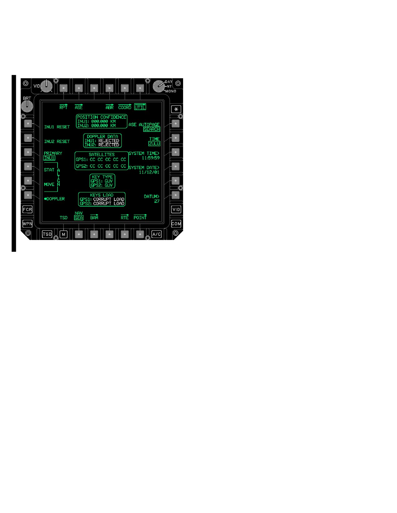
TM 1-1520-251-10
date data. The TSD UTIL page also provides both INUs posi-
The TSD UTIL page provides access to the following
tion confidence.
unique functions:
• T6
TSD UTIL button
• L1
INU1 RESET button
• L2
INU2 RESET button
• L3
PRIMARY button
• L4
ALIGN STATionary button
• L5
ALIGN MOVE button
• L6
DOPPLER button
• R1
ASE AUTOPAGE button
• R2
TIME button
• R3
SYSTEM TIME button
• R4
SYSTEM DATE button
• R6
DATUM button
• B2
Navigation Mode (NAV) button
3A.81.1 INU1/2 RESET Button. The INU1/2 RESET
buttons resets the INU1/2. It is primarily used when the
data from the INU is invalid or inaccurate.
3A.81.2 PRIMARY Button. The PRIMARY button is
used to select the active INU: INU1/2. The button state indi-
LBA5057A
cates the active (primary) INU whether selected automatically
by the system or manually by the operator. It is selectable
Figure
3A-101.
TSD UTIL Page
only when both INUs are operational and equal in status.
Use or disclosure of this information is subject to the restriction(s) on the title page of this document.
3A-116
Change 3
TM 1-1520-251-10
3A.81.3 ALIGN STATIONARY (STAT) Button. The
3A.81.10 DATUM Button. The DATUM button allows
ALIGN STAT button is displayed only when the state of
entry of a new datum in place of the default datum entered
the NAV mode button is set to SEA and the primary and/or
at the mission planning station. If the pilot enters a D using
secondary INU has a position from the GPS or has been
the KU, the system returns to the default datum and auto-
manually entered and that it is ready to initiate a stationary
matic datum updates, based on the current waypoints and
navigation system alignment.
their datums in the current route being flown.
3A.81.4 ALIGN MOVE Button. The ALIGN MOVE but-
ton displayed only when the state of the NAV mode button is
NOTE
set to SEA and the primary and/or secondary INU has a posi-
tion from the GPS or has been manually entered and that it is
When the INU is reset or power is applied to
ready to initiate a moving navigation system alignment.
the INU, the MPD will not display symbols
These are only displayed when on the ground in SEA mode.
that use INU information until the INU deter-
mines that its data is valid.
3A.81.5 DOPPLER Button. The DOPPLER button en-
ables or disables the Doppler.
3A.81.6 ASE AUTOPAGE Button. The ASE AUTO-
3A.81.11 Navigation (NAV) Mode Button. The NAV
PAGE button is used to select the state or condition of an
mode button selects the navigation mode: (LAND or SEA)
acquiring threat system which causes autopaging of
The primary System Processor (SP), upon generator power
threat warning information. The ASE AUTOPAGE is
up, automatically controls initialization and alignment of the
crewstation independent. The available selections are:
EGIs of the aircraft. Upon system power up, the last NAV
mode stored LAND or SEA, at power down will be selected
• SEARCH
automatically by the SP. The flight crew should confirm the
correct moding of LAND or SEA (SEA-Stationary or Moving)
• ACQUISITION
for the initialization/alignment process based on the current
• TRACK
aircraft configuration. After takeoff, (in-flight) the Navigation
Mode switch is used to select LAND or SEA using the criteria
• OFF
of where the aircraft is to be primarily operated for the mis-
sion. The LAND mode is used when operating primarily over
3A.81.7 TIME Button. The TIME button sets the dis-
terrain. The SEA mode is used when operating primarily over
play mode of time to LOCAL or ZULU.
water. When the LAND or SEA mode selection is made in-
flight, there will be no apparent change to the flight crew (with
3A.81.8 SYSTEM TIME Button. The SYSTEM TIME
the exception of the displayed LAND or SEA mode) but the
button sets the current LOCAL or ZULU time. The ZULU
navigation system will change the weighting of the Doppler
time must be entered before the LOCAL time. When a ZULU
velocity data to provide the best navigational accuracy (most
System Time is entered, the system processor sets its clock
significantly during degraded navigation modes).
to the entered time, and sends this time to the respective pri-
mary and secondary EGIs if their respective GPS is not track-
ing enough satellites. To determine if the GPS used the time,
3A.81.12 POSITION CONFIDENCE Status Win-
monitor the Satellite Status window. If the time entered is
dow. The POSITION CONFIDENCE status window in
used, the respective GPS Satellite ID numbers in the Satellite
the upper area of the page presents position confidence
Status window, will momentarily blank, then reappear.
status for INU1 and INU2. This value represents the 95%
probable radial position error of the position estimate of
3A.81.9 SYSTEM DATE Button. The SYSTEM DATE
latitude and longitude. It is displayed in WHITE when the
button sets the current date. When a system date is en-
value is greater than 50 meters, FAILED, or when the INU
tered, the system processor sets its Date to the entered
is not installed.
system date, and sends this date to the respective primary
and secondary EGIs if their respective GPS is not tracking
enough satellites. To determine if the GPS used the date,
monitor the Satellite Status window. If the date entered is
3A.81.13 DOPPLER DATA Status Window. The DOP-
used, the respective GPS Satellite ID numbers in the Sat-
PLER DATA status window provides the Doppler aiding
ellite Status window, will momentarily blank, then reap-
status of INU1 and INU2: USED, REJECTED (WHITE), or
pear.
MEMORY (WHITE).
Use or disclosure of this information is subject to the restriction(s) on the title page of this document.
Change 2
3A-117
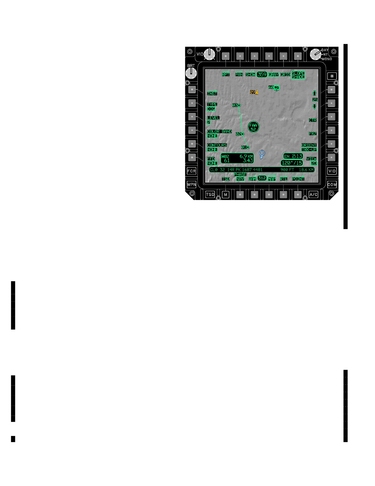
TM 1-1520-251-10
3A.81.14 SATELLITE Status Window. The SAT-
ELLITE status window provides the satellite number(s)
that the EGI is attempting to track. The box indicates that
a particular satellite is being tracked.
3A.81.15 KEY TYPE Status Window. The KEY TYPE
status window provides an indication to the crewmember
what type of key has been loaded into GPS receivers 1
and 2. If a Group Unique Variable (GUV) is loaded this sta-
tus window will show GUV. If a Weekly key is loaded the
status window will be blank, but the GPS keys status win-
dow will indicate LOADED.
3A.81.16 KEYS LOAD Status Window. The KEYS
LOAD status window provides the current state of the
GPS keys loaded into GPS receivers 1 and 2. The follow-
ing states are valid for display:
• ERASE FAIL (WHITE)
• NONE (WHITE)
• CORRUPT LOAD (WHITE)
• VALID
LBA5056B
• INCORRECT (WHITE)
• VERIFIED
Figure
3A-102.
MAP Page (DIG Map)
• LOADED
a.
GRAY Button. The GRAY maintained option but-
3A.82 MAP PAGE
ton is only displayed when the MAP type is set to DIG.
The MAP page (fig 3A-102) provides the crew with the con-
When the GRAY button is selected, DTED underlay is dis-
played in shades of gray. When GRAY is not selected,
trols for selecting the MAP underlay for display on the TSD
DTED underlay is displayed in shades of green.
and the orientation selection for how the TSD and symbology
are displayed relative to the ownship.
b. GRID Button. Selecting the GRID maintained
3A.82.1 MAP Page - DIG Map. The MAP page with
option button will display grid lines on the TSD. With the
DIG as the selected TYPE (fig 3A-102) displays a map
GRID button selected, the grid status window is displayed
based on DTED elevation posts which can have line and
in the upper right corner of the TSD. GRID will default to
area features overlaid on top of it. This page provides ac-
ON for all maps except CHART 1:50 and CHART 1:100.
cess to the following unique functions:
• T4
GRAY button
c. SLOPE SHADE Button. The SLOPE SHADE
maintained option button is only displayed if TYPE is set
• T5
GRID button
to DIG, CHART, or SAT and DTED is available on the
• T6
SLOPE SHADE button
DTC. The SLOPE SHADE button is used to enable/dis-
able slope shading. Slope shading provides a 3D effect to
• L2
TYPE button
DTED data. The SLOPE SHADE button is automatically
• L3
LEVEL button
enabled when the DIG option of the TYPE button is se-
• L3
SCALE button
lected. It is disabled when any other option of the TYPE
button is selected. The “phantom light source” for shading
• L4
COLOR BAND button
is fixed to the upper left corner of the format. For DIG and
• L5
CONTOURS button
Chart maps, the slope shading is based on the level of
DTED corresponding to the SCALE button. For SAT
• L6
FFD button
maps, it always is based on Level 2 DTED. (Slope shad-
• R5
ORIENT button
ing will not be displayed in areas which do not have DTED
• R6
VIEW button
information.)
Use or disclosure of this information is subject to the restriction(s) on the title page of this document.
3A-118
Change 3