HELICOPTER, ATTACK, AH-64D LONGBOW APACHE. TECHNICAL MANUAL (2002) - page 6
TM 1-1520-251-10
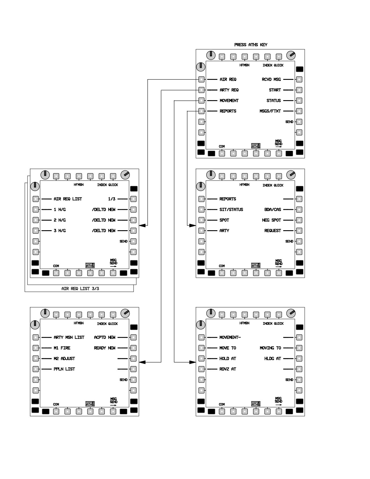
3.53BI.4 AIR REQUEST Pages.
mission list is accomplished by pressing the paging (up-
per right) button on the MPD. Accessing a stored Air Mis-
sion Request Summary page is accomplished by pressing
a. Description. The Air Request (AIR REQ) list can
the left button adjacent to desired mission. Complete mis-
store up to eight fire mission requests. The three index
sion information will be displayed. Initiating a new mission
pages display observer mission number, type of ord-
request is accomplished by pressing a NEW key - button
nance, firing element (LAUNCHER/subscriber) to which
of an available mission number on the Air Request list, se-
the request was sent, and mission status. This list is for
lecting air mission type, entering the required parameters,
originating mission requests. Incoming new missions are
receiving the summary, and transmitting the data
stored in the Received Message file. Stepping through the
(fig 3-62BW and 3-62BX).
Use or disclosure of this information is subject to the restriction(s) on the title page of this document.
Change 3
3-66.69
TM 1-1520-251-10
LBA5164
Figure 3-62BW. AIR REQ, ARTY REQ, MOVEMENT, AND REPORTS MENU STRUCTURE
Use or disclosure of this information is subject to the restriction(s) on the title page of this document.
3-66.70
Change 3
TM 1-1520-251-10
COMMAND SELECT
OBSERVER
LAUNCHER
93H
REQUEST
ACCEPT
LAST RECEIVED MESSAGE
READY
FIRE
1ST
2ND
SHOT
SHOT
EOM
LBA5165
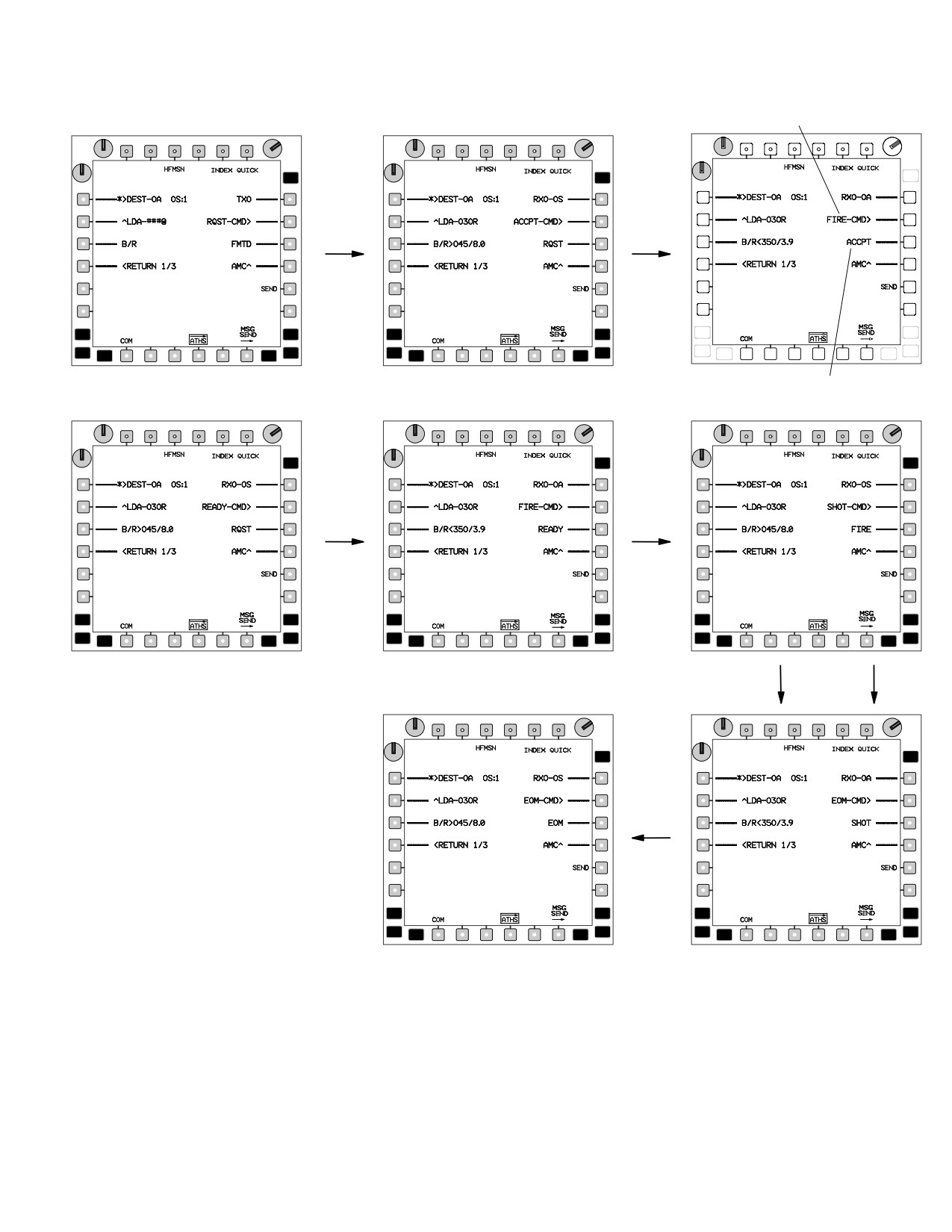
Figure 3-62BX. SIMPLIFIED DIGITAL REMOTE HELLFIRE ATHS - TACFIRE AIR MISSION
(1) Types of air missions are as follows:
(b) OTHER ORDNANCE. Seven selections,
NO PREF, ATGM, GUN, HE, ILLUM, SMOKE, and
CHAFF.
(a) HELLFIRE. The number of rounds to be
fired is requested and guidance is by other than the
launching element.
(c) NO PREF.
Use or disclosure of this information is subject to the restriction(s) on the title page of this document.
Change 3
3-66.71
TM 1-1520-251-10
(2) Storing/Sending Air Mission Fire Request
(3) Digital Remote HELLFIRE Laulcher (L) and
For Ordanance Other Than Remote HELLFIRE.
Designator (D) Mission Execution.
1. Locate target - CAQ or KU enter as required.
•
Remote HELLFIRE (REMOTE HLFR)
NOTE
mission request. The paging required for
a simplified request (fig 3-62BX).
The last CAQ’d (T50 or etc.) will automati-
• Launcher AUTO SHOT should be set to
cally fill the target location data field. Subse-
ON to enable automatic TOF messaging
quent target CAQing targets will overwrite
from the launcher to designator at trigger
the target data.
pull.
• The launcher’s HFMSN should be boxed
2.
COM page - Press as required.
to enable automatic CPG weapons mod-
ing. Selecting the button will box and un-
3.
MSG SEND page - Select.
box HFMSN.
4.
ATHS page - Select.
NOTE
5.
INDEX button - Press as required to display
When HFMSN is boxed T51 it will be auto-
ATHS - TACFIRE index page.
matically populated with the coordinate data
from the Hellfire message. T51 target data
6.
AIR REQ line - key button - Press.
will be overwritten with the last CAQ’d target
7.
Line (1 - 8) - Select mission number on which
when the operator toggles the HFSM but-
mission is to be entered. NEW button - Press.
ton.
• Set FAT on STATUS page to insure valid
8.
MSN TYPE - Press appropriate button.
TOF message. FAT is not integrated with
9.
As pages sequence, press appropriate button.
the 1553B bus.
• The Mission Status will change from RE-
10.
Air Mission Summary page - Review and
QUESTED to ACCEPTED, READY,
change parameters as required.
FIRE, and SHOT. At completion of mis-
To execute a fire request, perform steps 9 and
sion an END OF MISSION message
10.
should be sent.
1.
(D) ATHS - Select.
11.
On Air Mission Summary page, SEND button -
Press.
2.
(D) INDEX - Select as required.
12.
ATHS button - Press and repeat steps 1
3.
(D) AIR REQ - Select.
through 8 above for each net as required.
4.
(D) NEW (as desired) - Select next available air
To recall and send a stored mission, perform
mission.
steps 11 through 14.
NOTE
13.
INDEX button - Press as required to display
There are three pages (3/3) of NEW AIR
ATHS - TACFIRE index page.
MSN’s available, select the next available
AIR MSN.
14.
AIR REQ line - key button - Press.
5.
(D) HELLFIRE - Select.
15.
Desired mission (1 - 8) line number - Select.
6.
(D) Locate target - CAQ or KU enter as re-
16.
R1 button - Press to display Air Mission Sum-
quired.
mary page.
NOTE
17.
*>DEST button - Enter SUB, TEAM or BC ad-
The last target CAQ’d (T50 or ect.) will auto-
dress as desired through KU.
matically fill the target location data fill. Sub-
18.
On Air Mission Summary page, SEND button -
sequent target CAQing will overwrite the tar-
Press.
get data.
Use or disclosure of this information is subject to the restriction(s) on the title page of this document.
3-66.72
Change 3
TM 1-1520-251-10
7. D) TARGET type - Select and set.
• The launcher must verify that the target is
within range based upon the environ-
8.
(D) ACTIVITY - Select and set
mental conditions. The range is set to
flash at ranges greater than 4 KM. The
9.
(D) 1/3 - Select and advance to page 2/3.
bearing to the target is relative to the
launcher in this case and the > indicates
10.
(D) MST (missile separation time) TRAJ, Code/
the closest direction to turn to the target.
quantity - Set/verify.
•
Range and bearing are displayed appro-
priately for the aircraft location (launcher
NOTE
and designator).
The LDA/SEP L2 on 2/3 should be ignored.
Data will not accurately display on page 2/3
17.
(L) CMD line - Verify ACCPT is displayed.
until both the DEST subscriber 3/3 has been
entered and valid subscriber data is avai-
18.
(L) SEND - Select and note send/receive advi-
lable. Valid subscriber data is automatically
sory status R1.
provided if a previous situation report was
received or an ATHS-TACFIRE position
query was performed. Page 3/3 also dis-
19.
(L) - CMD line - Verify that READY is now dis-
plays the LDA/SEP data bloc.
played.
11.
(D) Select 2/3 - Advance to page 3/3 and verify
20.
(L) SEND - Select and not send/receive adviso-
Range/Bearing to TGT.
ry status R1.
12.
(D) >DEST - ?? - Select and enter subscriber
ID.
21.
(D) - CMD line - Verify that FIRE is now dis-
played.
13.
(D) SEND - Select and note send/receive advi-
sory status R1.
22.
(L) SEND - Select and note send/receive advi-
sory status R1.
14.
(L) ATHS MSG - Receive. Select INDEX page
and RCVD MSG buttons.
23.
(L) Missile in constraints, FIRE missile, and
15.
(L) Message buffer address L2, L3, or L4 - Se-
auto - send or manual send SHOT CMD.
lect to open AIR REQ Message.
24.
(D) - Monitor TOF, LASE target at delay time.
16.
(L) LDA/SEP, B/R, Mode, Code, & Qty - Verify
data.
25.
(L) - FIRE second missile at MST, if required.
NOTE
• The Launcher must verify the LDA and
26.
(D) - Monitor TOF, LASE target for second mis-
SEP angle. The LDA is the laser designa-
sile.
tion angle and is the area in front of the
launching aircraft that the designating air-
27.
(D) - CMD line - Set to EOM.
craft should avoid. This angle is +/- 30 de-
grees of the launchers gun-target line (soft-
28.
(D) - SEND - Select and note send/receive ad-
ware is set to flash at +/- 20 degrees).
visory status R1.
• The Separation angle (SEP) is +/- 60 de-
grees from the target back towards the des-
ignator aircraft. This is the angle that the
NOTE
designator should be inside to preclude a
missile miss due to laser angle to the mis-
The receipt of the EOM will automatically
sile. The SEP angle will flash when the
mode the CPG’s weapon systems back to
angle is greater than 60 degrees.
their previous settings.
Use or disclosure of this information is subject to the restriction(s) on the title page of this document.
Change 3
3-66.73
TM 1-1520-251-10
3.53BI.5 Artillery Request Pages.
(5) Copperhead (CPHD).Target position is de-
fined as NEW or Known Point and point number is pro-
a. Description. The mission data contained in the DIM
vided to the firing element.
is formatted to be consistent with the TACFIRE Artillery Fire
Direction Center (FDC) system and associated forward ob-
c. Artillery Fire Requests.
server digital message devices (DMD). Artillery mission com-
There are three types of artillery fire requests - pre-
mand selection is initially entered on the ARTY MISSION
planned, new, and Copperhead.
SUMMARY page automatically as REQ. Upon receipt of the
TACFIRE FDC message-to-observer (MTO), the mission
d. Preplanned Fire Requests.
command will automatically change to FIRE. A READY com-
mand will be displayed if the Battery Computer System
To insert a preplanned fire request, proceed as follows:
(BCS) is online with TACFIRE. Target position (range and
1. COM page - Press as required.
bearing from the helicopter) is automatically calculated. By
pressing the TGT PSN (target position) button, the operator
2. MSG REC or MSG SEND page - Select.
can manually enter the UTM grid, range, bearing, and altitude
of the target on subpages if required. The Artillery Request
3. ATHS page - Select.
List stores two active artillery missions and two preplanned
mission requests on the Preplanned Mission List subpage.
4. INDEX button - Press, as required, to display
Accessing either active mission is accomplished by pressing
ATHS - TACFIRE INDEX page.
the M1 or M2 button on the ARTY REQ list page. To review
a preplanned mission, pressing the PPLN LIST button on the
5. ARTY REQ line - key button - Press.
Preplanned Mission List page will cause the Preplanned Mis-
6. NEW line - key button - Press (On line opposite
sion Summary page to display.
mission to be replaced).
NOTE
7. REQ PPLN button - Press.
In order to store a preplanned mission, a pre-
8. Mission type - Select either FPF or CPHD as
plan request must be executed and stored as
desired.
a standard artillery preplan request. Then the
mission must be inserted into preplan list.
NOTE
If KNPT TGT is selected, entry of two - digit
Initiating a new artillery mission request is accomplished
KNPT number is required.
by pressing the NEW line - key button of an available mis-
sion number, selecting artillery mission type, following
9. KNPT TGT or NEW TGT - Select as appropri-
prompts through the subpages, reviewing summary page,
ate.
and transmitting data.
10. ARTY mission summary page will appear -
b. Types of artillery mission requests are as follows:
Press SEND. Wait for preplanned MTO then
continue.
(1) NEW TGT. Observer defines target type and
strength.
11. INDEX button - Press to return to ATHS - TAC-
FIRE index page.
(2) Known Point (KNPT TGT). The observer de-
fines a point which is a location previously identified and num-
12. ARTY REQ line - key button - Press.
bered, known both to the requestor and to the artillery FDC.
13. PPLN LIST button - Press.
The requestor then provides target type and strength.
14. P1 or P2 - Press NEW as desired.
(3) QUICK. Requestor enters only a known
point. All other data is known by the artillery FDC.
15. L2 - Press on preplan insertion pages.
(4) Preplanned (REQ PPLN). Observer pro-
16. Repeat steps 1. through 11. to insert a second
vides type of fire request (either Final Protective Fire
preplanned mission.
(FPF) or Copperhead (CPHD) guided munitions). Only
NOTE
one FPF can be preplanned at a time; however, both pre-
planned missions can be Copperhead. The requestor
If the PPLN mission is requested as M1, it
then provides target position and known point number.
can only be stored as P1.
Use or disclosure of this information is subject to the restriction(s) on the title page of this document.
3-66.74
Change 3
TM 1-1520-251-10
e. New Artillery Fire Mission Request.
7. To accomplish in active mission, M1 or M2 but-
ton - Press as desired.
To initiate a new fire mission, proceed as follows:
8. CPHD - Press.
1. Locate target - CAQ or KU enter as required.
NOTE
NOTE
If KNPT TGT is selected, entry of two - digit
KNPT number is required.
The last target CAQ’d (T50 or ect.) will auto-
matically fill the target location data fill. Sub-
9. NEW TGT or KNPT TGT - Select as appropri-
sequent target CAQing will overwrite the tar-
ate.
get data.
10. ARTY mission summary page will appear - Re-
2. COM page - Press as required.
view ARTY mission summary page and change
as required.
3. MSG REC or MSG SEND page - Select.
11.
*>DEST button - Enter SUB, TEAM or BC ad-
4. ATHS page - Select.
dress as desired through KU.
5. INDEX button - Press, as required, to display
12. SEND button - Press.
ATHS - TACFIRE INDEX page.
3.53BI.6
MOVEMENT Command Communica-
6. ARTY REQ line - key button - Press.
tions. The MOVEMENT pages allow position instruc-
tions to be transmitted without voice communication. The
7. NEW button opposite mission (M1 or M2) to be
DIM operator can issue directions to specific or all team
replaced - Press.
members to MOVE TO, HOLD AT, rendezvous (RDZV) at;
8. Mission type - Press applicable button and en-
or inform team members MOVlNG TO or HLDG AT a loca-
ter required parameters on subsequent pages
tion. The locations can be preset to allow QUICK commu-
until all data is inserted.
nication. In addition, the MOVEMENT pages allow auto-
matic transmission of current position through MY
9. Review mission on summary page and make
POSITION button and free text communication through
changes as required.
the OTHER button.
10.
*>DEST button - Enter SUB, TEAM or BC ad-
a. MOVEMENT Command Transmission.
dress as desired through KU.
Transmit movement commands as follows:
11. SEND button - Press.
1. COM page - Press as required.
f. Copperhead Fire Mission - Active and Pre-
2. MSG REC or MSG SEND page - Select.
planned.
3. ATHS page - Select.
To accomplish a Copperhead fire mission, proceed as fol-
lows:
4. INDEX button - Press, as required, to display
ATHS - TACFIRE INDEX page.
1. Locate target - CAQ or KU enter as required.
5. MOVEMENT line - key button - Press.
NOTE
6. Appropriate movement type button - Press.
The last target CAQ’d (T50 or ect.) will auto-
7. Appropriate destination select button - Press.
matically fill the target location data fill. Sub-
sequent target CAQing will overwrite the tar-
NOTE
get data.
Pressing the OTHER button will display
2. COM page - Press as required.
freetext message entry page where a manu-
al entry can be made using KU.
3. MSG REC or MSG SEND page - Select.
8. Mission summary page - Review and change as
4. ATHS page - Select.
required.
5. INDEX button - Press, as required, to display
9.
*>DEST button - Enter SUB, TEAM or BC ad-
ATHS - TACFIRE INDEX page.
dress as desired through KU.
6. ARTY REQ line - key button - Press.
10. SEND button - Press.
Use or disclosure of this information is subject to the restriction(s) on the title page of this document.
Change 3
3-66.75
TM 1-1520-251-10
3.53BI.7 REPORT Communications. The REPORTS
NOTE
pages (fig. 3-60) allow the observer to provide various in-
The last target CAQ’d (T50 or ect.) will auto-
formation to team and net members such as: Situation/
matically fill the target location data fill. Only
status (SIT/STATUS) which reports the observers own sit-
one location data fill is available.
uation, SPOT which reports target activity, ATI or provide
intelligence reports to artillery units, BDA to report battle
2. COM page - Press as required.
damage assessments, CAS to report casualty assess-
ments, NEG SPOT, and REQUEST to request a report
3. MSG REC or MSG SEND page - Select.
from another subscriber.
4. ATHS page - Select.
a. Situation/Status (SIT/STATUS). Report Trans-
5. INDEX button - Press, as required, to display
mission. To transmit observers situation and/or status,
ATHS - TACFIRE INDEX page.
proceed as follows:
6. REPORTS line - key button - Press.
NOTE
7. SPOT button - Press.
The situation report will automatically in-
NOTE
clude the ownship’s fuel, AMMO (30mm),
rocket, and missile (FARM) quantities. No
Three different target types may be entered
operator input is required.
for each SPOT report.
8. TARGET type - Press appropriate button.
1. COM page - Select.
9. Target strength (STR) - Press appropriate but-
2. MSG REC or MSG SEND page - Select.
ton.
10. R1 button - Press.
3. ATHS page - Select.
11. ALT button - Press as desired.
4. INDEX button - Press, as required, to display
12. Target (TGT) ACTIVITY - Select as desired. If
ATHS - TACFIRE INDEX page.
MOVING is selected, proceed to step 10. If STA-
TIONARY is selected, proceed to step 11.
5. REPORTS line - key button - Press.
13. Target direction - Press appropriate button.
6. Activity to report - Press the desired activity but-
14. R1 button - Press.
ton: HOLDING, CONT MSN, OBS TGT, EN-
GAGING.
15. Mission summary page - Review and change as
required.
7. Report summary page - Review and change as
16.
*>DEST button - Enter SUB, TEAM or BC ad-
required.
dress as desired through KU.
8.
*>DEST button - Enter SUB, TEAM or BC ad-
17. SEND button - Press.
dress as desired through KU.
c. Battle Damage Assesment (BDA) REPORT
Transmission.
9. SEND button - Press.
To provide battle damage assessments, proceed as follows:
1. COM page - Press as required.
b.
SPOT REPORT Transmission.
2. MSG REC or MSG SEND page - Select.
To transmit a spot report, proceed as follows (fig.
3. ATHS page - Select.
3-62BW):
4. INDEX button - Press, as required, to display
ATHS - TACFIRE INDEX page.
1. Locate target - CAQ, store or receive as re-
quired.
5. REPORTS line - key button - Press.
Use or disclosure of this information is subject to the restriction(s) on the title page of this document.
3-66.76
Change 3
TM 1-1520-251-10
6. BDA/CAS button - Press.
9. Target strength - Press appropriate button.
7. BDA summary page - Press appropriate button
10. R1 button - Press.
and manually enter information using KU.
NOTE
11. RAD/LGTH, WIDTH, and ATTITUDE buttons -
Press as appropriate.
The last target CAQ’d (T50 or etc.) will auto-
matically fill the target location data fill.
12. R1 button - Press.
8.
*>DEST button - Enter SUB, TEAM or BC ad-
dress as desired through KU.
13. ATl summary page - Review and change as re-
9. SEND button - Press.
quired.
d. CASUALTY (CAS) REPORT TRANSMISSION.
NOTE
To provide casualty reports, proceed as follows:
The last target CAQ’d (T50 or etc.) will auto-
1. COM page - Press as required.
matically fill the target location data fill.
2. MSG REC or MSG SEND page - Select.
14.
*>DEST button - Enter SUB, TEAM or BC ad-
dress as desired through KU.
3. ATHS page - Select.
4. INDEX button - Press, as required, to display
15. SEND button - Press.
ATHS - TACFIRE INDEX page.
5. REPORT line - key button - Press.
f. REPORT Requesting From Another Subscriber.
6. BDA/CAS button - Press.
To request a report from another subscriber, proceed as
follows:
7. CAS summary page - Press appropriate button
and manually enter information using KU.
1.
COM page - Press as required.
NOTE
2.
MSG REC or MSG SEND page - Select.
The last target CAQ’d (T50 or etc.) will auto-
matically fill the target location data fill.
3.
ATHS page - Select.
8.
*>DEST button - Enter SUB, TEAM or BC ad-
dress as desired through KU.
4.
INDEX button - Press, as required, to display
9. SEND button - Press.
ATHS - TACFIRE INDEX page.
e. Artillery Intellegence REPORT (ATI) Transmis-
5.
REPORTS line - key button - Press.
sions.
To transmit an artillery intelligence (ATI) report, proceed
6.
REQUEST button - Press.
as follows:
7.
On report request select page - Press appropri-
1. COM page - Press as required.
ate button to designate type of report desired.
2. MSG REC or MSG SEND page - Select.
8.
DEST - button on summary page - Press and
3. ATHS page - Select.
enter subscriber identifier from which report is
4. INDEX button - Press, as required, to display
desired using KU.
ATHS - TACFIRE INDEX page.
9.
Request report summary page - Review and
5. REPORTS line - key button - Press.
change as required.
6. ATI button - Press.
10.
“>DEST button - Enter SUB, TEAM or BC ad-
7. REL - Scroll through reliability option until de-
dress as desired through KU.
sired option is displayed.
8. Target type - Press appropriate button.
11.
SEND button - Press to transmit request.
Use or disclosure of this information is subject to the restriction(s) on the title page of this document.
Change 3
3-66.77
TM 1-1520-251-10
3.53BI.8
STATUS Pages. The STATUS pages (fig
c. Weapons Status - All Subscribers.
3-60) provide a means of maintaining and reviewing the
last position, fuel, ammunition, rocket, and missile
To obtain subscriber weapons status, proceed as follows:
(FARM) status of subscribers. STATUS pages are auto-
matically filled each time a subscribers situation report is
1. COM page - Press as required.
received. The status pages also maintain the ownship’s
2. MSG REC or MSG SEND page - Select.
dynamic status. The weapons format will depend on
whether the subscriber is defined in an AIR NET or a TAC-
3. ATHS page - Select.
FIRE NET. The subscriber pages will be automatically up-
dated upon receipt of a situation/status report. There is no
4. INDEX button - Press, as required, to display
need to input or edit ownship data.
ATHS - TACFIRE INDEX page.
a. OWN STATUS.
5. STATUS button - Press.
To review own status, proceed as follows:
6. SUBS WPNS button - Press. Review weapons
status of net subscribers as DIM automatically
1. COM page - Press as required.
sequences from the first subscriber in NET 1 to
the last subscriber in NET 8.
2. MSG REC or MSG SEND page - Select.
7. Paging button - Press to return to status index
3. ATHS page - Select.
page.
4. INDEX button - Press, as required, to display
d. Present Position Status - All Subscribers.
ATHS - TACFIRE INDEX page.
To obtain present position information on all net subscrib-
ers, proceed as follows:
5. STATUS line - key button - Press.
1.
COM page - Press as required.
6. OWN WPNS or OWN PPSN button - Press as
desired.
2.
MSG REC or MSG SEND page - Select.
7. For OWN WPNS entry, laser designator code -
3.
ATHS page - Select.
Enter using KU and press paging select button
(1/1) to return to status index page.
4.
INDEX button - Press, as required, to display
ATHS - TACFIRE INDEX page.
b.
OWN PPSN Entry.
5.
STATUS line - key button - Press.
NOTE
6. SUBS PPSN button - Press.
Present position, ALT, and FUEL is conti-
nously updated and maybe manually edited.
NOTE
• Subscriber status will begin with the first
To Manually change proceed as follows:
subscriber in NET 1 and display, in order,
through the last subscriber in NET 8 as
1. KU and UTM button - Press and enter coordi-
paging button is pressed.
nates.
• UTM button can be alternately pressed to
display UTM grid coordinates or range
2. ALT button - Press and enter altitude.
and bearing of subscriber status being
displayed.
3. FUEL button - Press and enter quantity.
7.
If desired, return to status index page by press-
4. Paging select (1/1) - Press to return to status in-
ing paging button once more after last subscrib-
dex page (fig 3-60).
er status is displayed.
Use or disclosure of this information is subject to the restriction(s) on the title page of this document.
3-66.78
Change 3
TM 1-1520-251-10
e. Weapons/Present Position STATUS - Single
3.53BI.9 FREE TEXT/PRESET Pages. The FREE TEXT/
Subscriber.
PRESET message pages (fig 3-62BV) allow the observer to
compose and transmit any message up to 36 characters (two
1. COM page - Press as required.
lines) at any time. Also, these pages allow messages to be
composed and stored for subsequent recall and transmission
2. MSG REC or MSG SEND page - Select.
at the appropriate time. The top message page includes a
MAYDAY for QUICK MAYDAY broadcasts, a CHECKFIRE
3. ATHS page - Select.
message for a QUICK cease fire broadcast, an authentica-
tion synchronization message to align the FDC codes to the
4. INDEX button - Press, as required, to display
DIM codes, and cancel checkfire message. The free text and
ATHS - TACFIRE INDEX page.
preset messages contain the same information. The free text/
preset messages are automatically addressed to the team
5. STATUS line - key button - Press.
subscriber identifier. the MAYDAY message is addressed to
the broadcast subscriber identifier, and contains the MAYDAY
6. SELECT button - Press.
message and own present position. The Authentication Syn-
chronization (AUTH) message is addressed to the broadcast
7. SUB - button - Press. Enter desired subscriber
subscriber identified in the start pages with whom the auto-
identifier using KU. Present position page will
matic authentication is to occur (normally TACFIRE). If, after
display.
transmission, a NAK is returned, the tables are out of syn-
chronization. TACFIRE will still get the message and change
8. Paging button - Press to review weapons sta-
tables to match the observers. TACFIRE will call back once
tus.
synchronization has been accomplished.
9. Weapons status paging button - Press to return
a. FREE TEXT Message Composotion and Trans-
to status index page.
mission.
f.
Subscriber Position STATUS.
To compose and transmit a free text message, proceed as
follows:
1.
COM page - Press as required
1. COM page - Press as required.
2.
MSG REC or MSG SEND page - Select
2. MSG REC or MSG SEND page - Select.
3.
ATHS page - Select
3. ATHS page - Select.
4.
INDEX button - Press, as required, to display
ATHS - TACFIRE INDEX page.
4. INDEX button - Press, as required, to display
ATHS - TACFIRE INDEX page.
5.
STATUS line - key button - Press.
5. MSGS/FTXT line - key button - Press.
6.
POS UPDT button - Press.
6. DEST button - Enter subscriber identifier using
7.
SUBS POSITION button - Press and review.
KU.
8.
Repeat steps 1 through 3.
NOTE
9.
SUBS NET button - Select appropriate NET.
When FREE TEXT - TEST is used for com-
munication check, data is not required.
10.
Repeat steps 4 and 5 as desired.
7. FREE TEXT button - Press to scroll between
11.
SUMMARY page - Review and select destina-
TEST and DATA as required.
tion.
12.
*>DEST button - Enter SUB, TEAM or BC ad-
8. Message - Enter any message up to 36 charac-
dress as desired through KU.
ters long using KU.
13.
SEND button - Press.
9. SEND button - Press to transmit message.
Use or disclosure of this information is subject to the restriction(s) on the title page of this document.
Change 3
3-66.79
TM 1-1520-251-10
b. PRESET Message Transmission.
d. MAYDAY Message Transmission.
To broadcast a MAYDAY message, proceed as follows:
To transmit any of up to six preset messages entered dur-
ing DIM initialization, proceed as follows:
1. COM page - Press as required.
2. MSG REC or MSG SEND page - Select.
1. COM page - Press as required.
3. ATHS page - Select.
2. MSG REC or MSG SEND page - Select.
4. INDEX button - Press, as required, to display
3. ATHS page - Select.
ATHS - TACFIRE INDEX page.
4. INDEX button - Press, as required, to display
5. MSGS/FTXT line - key button - Press.
ATHS - TACFIRE INDEX page.
6. MAYDAY button - Press.
5. MSGS/FTXT line - key button - Press.
7. Present position is automatically filled. To
change present position in UTM grid, POSITION
6. MSG PRESETS button - Press.
button - Press. Enter UTM using KU.
7. Select message to be transmitted by pressing
8. Broadcast identifier is automatically inserted to
button adjacent to appropriate message num-
change: DEST - button - Press and enter identi-
ber.
fier.
9. SEND button - Press.
8. DEST - button - Press and enter subscriber
identifier.
10. To return to ATHS - TACFIRE index page, IN-
DEX button - Press.
9. SEND button - Press.
e. A U T H E N T I C A T I O N Synchronization
10. To return to ATHS - TACFIRE index page, IN-
Transmission.
DEX button - Press.
To broadcast an Authentication Synchronization transmis-
sion, proceed as follows:
c. CHECKFIRE Message Transmission.
1. COM page - Press as required.
To broadcast a cease fire message to all subscribers, pro-
2. MSG REC or MSG SEND page - Select.
ceed as follows:
3. ATHS page - Select.
1. COM page - Press as required.
4. INDEX button - Press, as required, to display
2. MSG REC or MSG SEND page - Select.
ATHS - TACFIRE INDEX page.
5. MSGS/FTXT line - key button - Press.
3. ATHS page - Select.
6. AUTH button - Press.
4. INDEX button - Press, as required, to display
ATHS - TACFIRE INDEX page.
7. DEST - button - Press. Enter identifier of sub-
scriber with which automatic authentication is
5. MSGS/FTXT line - key button - Press.
desired.
8. When desired, SEND button - Press.
6. CHECKFIRE button - Press.
NOTE
7. Broadcast identifier is automatically inserted to
• If authentication tables between sender
change: DEST - button - Press and enter identi-
and receiver are not synchronized, a
fier. using KU.
NAK will be returned. Sender should not
retransmit.
8. SEND button - Press.
• Receiver should change table positions
9. To return to ATHS - TACFIRE index page, IN-
and transmit to original sender with tables
DEX button- Press.
synchronized.
Use or disclosure of this information is subject to the restriction(s) on the title page of this document.
3-66.80
Change 3
TM 1-1520-251-10
f. Cancel Checkfire Message Transmission.
subscriber list, will be stored and an advisory displayed; how-
ever, an ACK will not be transmitted back. A message re-
To broadcast a cancel checkfire message, proceed as fol-
ceived addressed to the Team or Broadcast identifiers will be
lows:
stored and an advisory displayed but an ACK will not be sent
to the originator. The RCVD MSG index will show the mes-
1. COM page - Press as required.
sage number, the identifier of the sender, a three character
identifier of message type, a six character field indicating the
2. MSG REC or MSG SEND page - Select.
message content, and the status of the message. If the mes-
sage has been reviewed, delete (DEL) will appear next to the
3. ATHS page - Select.
right hand button line; if not yet reviewed, NEW will appear.
4. INDEX button - Press, as required, to display
Another function of the received messages is that it allows
ATHS - TACFIRE INDEX page.
the observer to leave the ATHS-TACFIRE pages and still be
able to manage a fire mission. The fire mission summary
5. MSGS/FTXT line - key button - Press.
pages will be automatically updated upon the receipt of new
mission commands. Received FREE TEXT and movement
6. CANCKF button - Press.
messages can be deleted on the page that they are re-
7. DEST button - Press. Enter identifier of sub-
viewed. If delete is selected, the system will return to the re-
scriber as desired.
ceived message index page. Situation/status reports are au-
tomatically deleted after they have been reviewed and the
8. SEND button - Press.
information is stored in the status pages.
9. To return to ATHS - TACFIRE index page, IN-
a. Reviewing Received ATHS Messages.
DEX button - Press.
3.53BI.10 Received Messages.
There are three different ways to review a received mes-
sage. To review a received message, follow one of the
NOTE
procedures described:
ATHS - TACFIRE messages can only be
Procedure #1
opened and viewed from the ATHS MSG
RCVD page. The COM DIM MSG RCVD will
1. TSD page REC button (if the last message re-
only allow for the deletion of an ATHS - TAC-
ceived is a tactical message) - Press as re-
FIRE message.
quired. Upon selection of this button the page
The received message function of the DIM allows the observ-
will automatically switch to the RCVD MSG
er to access the received message list to review new mes-
page.
sages. It also allows the observer to review and delete any
2. Message to be reviewed - Select by pressing
previously received messages, to include received fire re-
button adjacent to appropriate message num-
quests. When an ATHS-TACFIRE DIM message is received,
ber.
it will be stored in the RCVD MSGS index of the DIM buffer
and an ATHS message advisory will appear on the MPD and
3. Delete message as appropriate.
EUFD. An audible MODEM communication squelch is readily
perceivable during the message transmission and reception.
Procedure #2
Twelve messages (12 per ATHS-TACFIRE radio) can be
stored for review and deletion when desired, except for situa-
1. COM page - Select.
tion/status reports which are automatically deleted upon re-
view. Messages received while the RCVD MSGS index is full
2. MSG REC page - Select.
will not be accepted, and the received advisory will not be dis-
3. Select TACFIRE message to be reviewed - Se-
played. When a message is received an acknowledge (ACK)
lect by pressing button adjacent to appropriate
is automatically transmitted back to the message originator
message number.
with no operator action required. Messages received which
are not recognizable, improperly addressed (net data incor-
4. RVW button - Press as required.
rect), or unprocessable will be ignored. The originator will not
have an ACK displayed and an ATHS-TACFIRE MESSAGE
5. Review message.
will not be displayed to the receiver. A message received
which is acceptable, but from an originator not defined in the
6. Delete message as appropriate.
Use or disclosure of this information is subject to the restriction(s) on the title page of this document.
Change 3
3-66.81
TM 1-1520-251-10
Procedure #3
6. Message to be reviewed - Select by pressing
button adjacent to appropriate message num-
1. COM page - Select.
ber.
2. MSG REC or MSG SEND page - Select.
7. Delete message as appropriate.
3. ATHS page - Select.
8. To return to ATHS - TACFIRE index page, IN-
DEX button - Press.
4. INDEX button - Press, as required, to display
ATHS - TACFIRE INDEX page.
b. ATHS MESSAGES. Table 3 - 3 lists all different
5. RCVD MSG line - key button - Press to display
ATHS messages that can be displayed on the MSG REC
received message index.
page.
Table 3 - 3F.
ATHS Messages
TYPE OF MESSAGE
MESSAGE DISPLAYED ON THE MSC REC PAGE
Free Text
FREE TEXT T
Airborne Battle Damage Assessment/Casualty Report
BDA REPORT T
Airborne Situation Report
FARM REPORT T
Position Update Request
PP QUERY T
Position Update Reply
PP REPORT T
Airborne Mayday
MAYDAY REPORT
Airborne Movement Command
MOVE COMMAND
AIrborne Spot Report
SPOT REPORT
Airborne Negative Spot Report
NEG SPOT REPORT
Airborne Fire Request
AIR FIRE REQUEST
Airborne Mission Command
AIR FIRE REQUEST
Airborne Check All
AIR FIRE REQUEST
Airborne Target Position Update
AIR FIRE REQUEST
Artillery Intelligence Report
ARTY INTL GRID
Fire Request Grid
ARTY FIRE RQST
Fire Request Quick
ARTY FIRE RQST
Fire Request Shift
ARTY FIRE RQST
Forward Observer Command
ARTY FIRE RQST
Subsequent Adjust
ARTY FIRE RQST
End of Mission and Surveillance
ARTY FIRE RQST
Message to Observer
MSG TO OBSERVER
Observer Location
OBSERVER READY
Intialization Message
BULK MESSAGE
All Other Messages
ATHS MESSAGE
Use or disclosure of this information is subject to the restriction(s) on the title page of this document.
3-66.82
Change 3
TM 1-1520-251-10
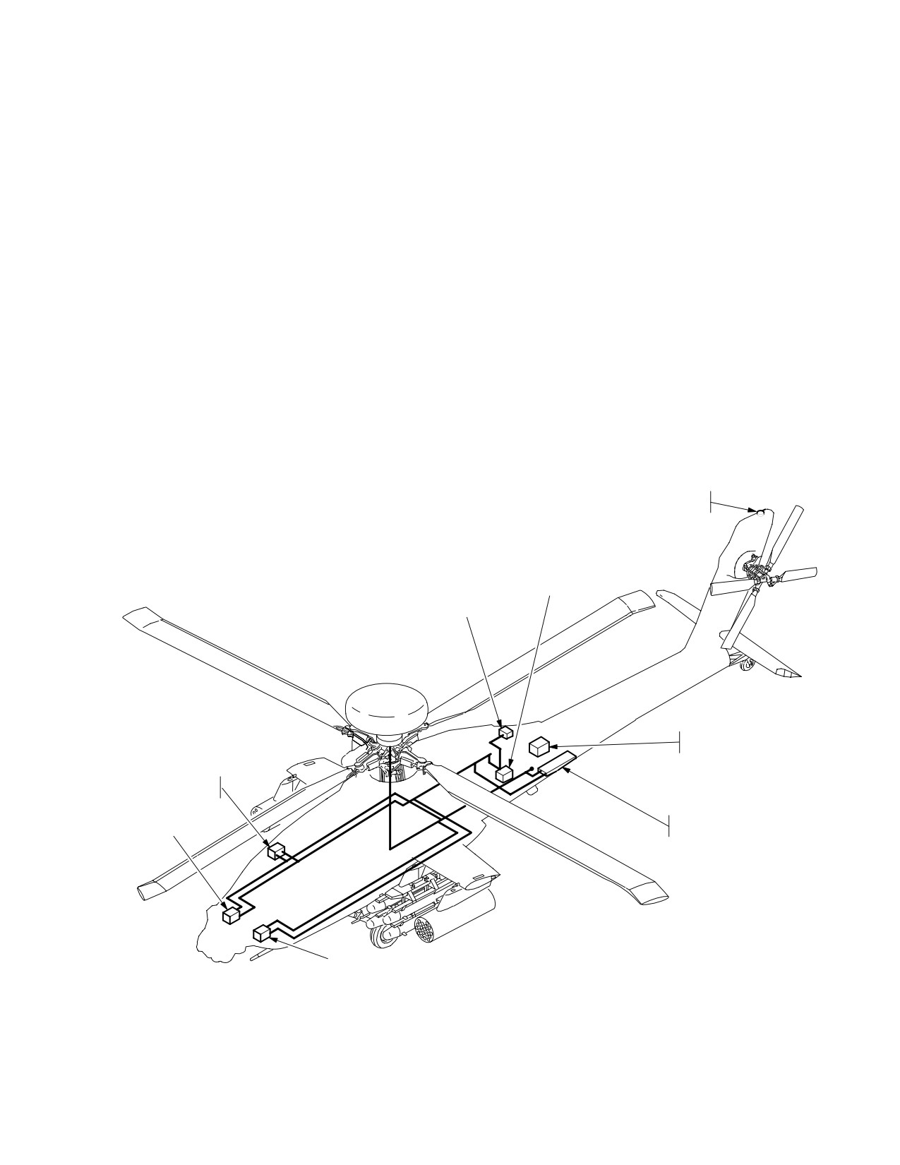
Section III. NAVIGATION SUBSYSTEM
3.54 INTRODUCTION
2. Doppler Radar Velocity Sensor (DRVS).
This section describes crew interface requirements for
3. Air Data System (ADS).
management of the navigation subsystem (fig. 3-63). The
navigation subsystem provides aircraft heading, attitude,
4. Radar Altimeter (RAD ALT).
Present Position (PP), velocity (relative to ground and air),
radar and barometric altitude, and distance information for
5. Automatic Direction Finder (ADF).
piloting and navigating. The navigation subsystem con-
sists of the following major components:
6. High Integrated Air Data Computer (HIADC).
1. Embedded Global Positioning System Inertial
Navigation System (EGI).
7. Flight Management Computer (FMC).
GPS
ANTENNA
HIADC
ADF
RECEIVER
RADAR
ALTIMETER
FLIGHT MANAGEMENT
COMPUTER
DOPPLER RADAR
EGI 2
VELOCITY SENSOR
EGI 1
LBA2400
Figure 3-63. Navigation Subsystem
Use or disclosure of this information is subject to the restriction(s) on the title page of this document.
3-67
TM 1-1520-251-10
3.55 EMBEDDED GLOBAL POSITIONING SYSTEM
last NAV mode stored (i.e. Land or Sea) at power down of
INERTIAL NAVIGATION SYSTEM (EGI)
the aircraft. If no boresight numbers have been stored, the
NAV system will provide an advisory on the UFD, prompt-
The aircraft has two EGIs which use internal accelerome-
ing the aircrew for input for the respective EGI and doppler
ters, rate gyro measurements, and external sensor mea-
boresight numbers. Once the EGIs have been provided
surements to estimate the aircraft state. Only one EGI
the boresight numbers and the NAV mode, the EGIs will
provides aircraft state information to aircraft systems
determine the aircraft attitude. Upon finding attitude (i.e.
while the second EGI is for backup. The external sensor
attitude displayed on the FLT page), the NAV system will
measurements include range and range rate from the
provide the EGIs with position information from the prima-
GPS, velocity from the DRVS, barometric altitude, and
ry EGIs GPS (if tracking satellites) or the NAV system’s
manual position updates from the system processor (SP).
last stored position at power down. If no GPS or last
Incorporated within the EGI is an Inertial Measurement
stored present position is available, the NAV system will
Unit (IMU) and the processing functions for performing the
provide an advisory prompt on the UFD directing the crew
inertial navigation computations, GPS navigation solu-
to enter a present position. If a GPS position is given to
tions, receiver management, and Kalman filter estimates
the EGIs to align to, the EGIs initial position confidence on
to support all aircraft and weapon systems requirements.
the TSD UTIL page will read approximately .031 km. If a
stored position is given to the EGIs to align to, the EGI ini-
The data derived from the EGI includes :
tial position confidence on the TSD UTIL page will read
approximately 9.00 km. When a position is manually en-
• Acceleration
tered to the EGIs to align to on the ground, the EGI initial
• Angular rate
position confidence on the TSD UTIL page will read
approximately .050 km. Upon the EGIs being given a
• Attitude
present position, the NAV system will provide an align-
ment command to the EGIs. The EGIs alignment time is
• Heading
approximately 4 minutes on the ground. When an in-flight
• Velocity
alignment is performed by an INU reset the alignment
time, with GPS tracking satellites with crypto keys verified
• Position
and doppler velocities available, is approximately 35 se-
• Position Error Estimate
conds. If an in-flight alignment is performed with doppler
velocity aiding only (no GPS), the alignment time is
a. System Description. The EGI is a velocity
approximately 6 minutes. The time to alignment is not sig-
aided, strapdown, ring laser gyro based inertial unit. The
nificantly affected by temperature. The heading tape
EGI unit also houses the 5 - channel GPS receiver. The
symbology is displayed and TSD Map Frozen Cue is re-
ring laser gyro operates on an optical principle called the
moved, upon the primary EGI completing alignment. The
Sagnac Effect which deals with the properties of light
reaching of alignment of the secondary EGI is noted by
beams traveling in opposite directions around a closed
the removal of the inhibit selection bar beside the primary
loop. In operation, two laser beams are directed around
INU selection on the TSD UTIL page. There is no effect on
the ring in opposite directions; clockwise and counter-
the NAV system accuracy if the engines are started, or if
clockwise. If the ring rotates in the clockwise direction
the main rotor is turning during alignment. The EGIs han-
while the light beams are in transit then the clockwise
dling of velocity information from the GPS or doppler is en-
beam will seem to travel a shorter distance than the count-
tirely automatic. If the different sources of velocity in-
er-clockwise beam. This is used as a measure of rotation
formation should become absent, or of low quality for use
by observing the interference pattern created at the end of
by the EGI, the EGI will automatically weight the use of ve-
the ring when the two laser beams mix together; the faster
locity sources available according to the quality of the ve-
the rotation, the greater the interference pattern.
locity source. The EGIs Kalman filter uses the velocity
sources along with it’s accelerometers to calculate the ulti-
b. Operation. Initialization and alignment of the EGI
mate aircraft state information. The primary EGI provides
is automatically controlled by the primary System Proces-
this aircraft state information to those onboard systems
sor (SP) upon generator power up of the aircraft. Upon
requiring it. The velocity vector, acceleration cue, vertical
power up, the SP provides the boresight numbers stored
speed indicator, and heading tape are driven by the pri-
in non-volatile memory, for each EGI and doppler, and the
mary EGI aircraft state information.
Use or disclosure of this information is subject to the restriction(s) on the title page of this document.
3-68
TM 1-1520-251-10
3.55.1 Global Positioning System (GPS).
maps and charts. Currently, many datums are used
throughout the world to produce maps. The standard for
a. System Description. The GPS receiver installed
US Forces is World Geodetic System 1984 (WGS 84).
in each EGI is a 5 - channel receiver. The receiver is capa-
However, many US Military Grid Reference System
ble of operating in either C/A code or encrypted P/Y code.
(MGRS) and foreign maps are still based on other da-
The Group User Variable (GUV) is the normal encryption
tums. Not correcting for different datums can cause signif-
key used. The GUV key is loaded into the EGI using a
icant errors. The coordinates for a point on the Earth’s sur-
KYK - 13 or equivalent device. When keyed the GPS re-
face in one datum will not match the coordinates from
ceiver will automatically use anti-spoof/jam capabilities
another datum for the same point. The Navigation System
when they are in use. The EGI keying connector is located
requires that the datum be entered with the coordinate
in the aft avionics bay on the multifill port panel. The EGI
data. If it is not entered, it will default to the present posi-
will retain the key through power ON/OFF/ON cycles. Be-
tion datum. The datum included with each set of coordi-
cause of safeguards built into the EGI, it is not considered
nate data allows the Navigation System to calculate the
classified when keyed. The antenna for the GPS receiver
compensations for different datums. The datum used is
is located on the top of the vertical stabilizer.
identified by a two digit number. Table 3-4 lists all of the
NOTE
datums that may be used with the Navigation System.
The GPS signal is vulnerable to jamming
Table 3-4. Datum Names and Codes
and spoofing operations. Under these con-
Datum Code Used
ditions some or all satellites may be un-
Datum
By Navigation
boxed and/or aircraft position, airspeed and/
Name/Description
System
or position confidence may be excessively
Adindan
01
high or changing quickly. Therefore continu-
ARC 1950
02
ous monitoring of the EGIs is required at all
Australian 66
03
times.
Bukit Rimpah: Indonesia
04
b. Operation. The operation of the GPS receiver is
Camp Area Astro
05
entirely automatic. The GPS receiver is powered when
the EGI is powered. If the GPS is keyed, it may take as
Djarkarta: Indonesia
06
long as 12 minutes to verify the key with the satellites. The
European 1950
07
GPS provides range and range rate information to the EGI
Geodetic Datum 1949
08
as well as position and time information to the System
Ghana
09
Processor (SP). When the GPS has tracked the first satel-
lite, it will update the date and time to the Navigation Sys-
Guam 1963
10
tem. There are no specific operator actions that may be
Gunung Segara: Indonesia
11
taken with the GPS system.
Gunung Serindung: Indonesia
12
c. Data Transfer Unit (DTU). The Data Transfer
Herat North
13
Unit (DTU) is located in the right hand forward pilots’ con-
Hjorsey
14
sole. The cartridge is programmed using the Aviation Mis-
Hu-Tzu-Shan
15
sion Planning System (AMPS). The AMPS writes the
coordinate files for waypoints, control measures, hazards,
Indian: Mean Value For Thailand
16
targets, and threats as well as routes and their associated
And Viet-Nam
waypoint numbers of destination. The NAV mode and
Ireland 1965
17
present position for the EGIs can be loaded from the car-
Kertau: West Malaysia
18
tridge if desired. On the aircraft, the SP handles all read-
Liberia 1964
19
ing and writing to the DTC, Whenever the Pilot/CPG
Local Astro
20
makes changes to any of the point files or routes, the SP
will automatically update the DTC with those changes,
Luzon
21
and will preserve those changes in case of a power tran-
Merchich
22
sient. If a power transient occurs, the SP will load the most
Montjong Lowe: Indonesia
23
recent data saved to the DTC. On initial power up on the
Minna
24
ground, the SP will load the initial mission data from the
North American Datum of 1927
25
DTC.
NAD 27 Alaska: Canada
26
3.55.2 Map Datums. Map datums are mathematical
models of the Earth used to calculate the coordinates on
Old Hawaii: Maui
27
Use or disclosure of this information is subject to the restriction(s) on the title page of this document.
Change 2
3-69
TM 1-1520-251-10
Table 3-5. Datum Names and Codes (cont)
• If the aircraft has been moved over one
Datum Code Used
nautical mile since it’s last power down
Datum
By Navigation
(LAT/LONG data differs more than one min-
Name/Description
System
ute from actual position) and does not ac-
quire satellites within a short time (three-
Old Hawaii: Oahu
28
five minutes) after power up, the following
Old Hawaii: Kauai
29
procedures will help insure a good align-
England Scot Wale
30
ment.
Qornoq
31
a. Aircraft Moved Over One Nautical Mile Since
Sierra Leone 1960
32
Last power Down.
Campo Inchauspe: Argentina
33
(1) Manual Procedure.
Chua Astro: Paraguay
34
(a) Ensure that the current Zulu date and time
Corrego Alegre: Brazil
35
are entered on the TSD UTIL page.
Provisional South American 1956
36
(b) Check the left side of the TSD page to see
Yacare: Uruguay
37
if the HDG selection is displayed. If so, select PSN and
Tananarive: South American
38
enter the aircraft’s current position. (The HDG selection
1925
must be displayed when entering the current position.) If
Timbali: East Malaysia
39
HDG is not displayed or the HDG selection is removed
Tokyo: Japan: Korea: Okinawa
40
while the current position data is being entered, perform
Voirol
41
an INU1 and INU2 reset and then quickly (within one min-
Special Datum: Indian Special
42
ute) enter the aircraft’s current position.
Special Datum: Luzon
43
(2) DTU Procedure.
Tokyo Special
44
(a) If the correct aircraft current position has
WGS 84 Special Datum
45
been entered on the DTU, selecting Navigation on the
WGS 72 (Sino-Soviet Bloc)
46
DTU page will automatically update the current stored
WGS 84 Standard Datum*
47
position and reset the EGI(s) if the Position Confidence
(PC) values are greater than 0.031 Km.
*All FAA Sectionals and FLIP use this datum for coordi-
b. EGI Position Updates (GPS and/or Doppler Aid-
nate data.
ing Not Available).
3.55.3 EGI Operational Procedures.
(1) EGI position updates can be accomplished
anytime the PSN selection on the TSD page is present
CAUTION
(Primary EGI Position Confidence value greater than
0.050 Km).
The GPS system may provide erroneous
(2) If the position is not updated before the Position
system data during normal GPS opera-
Confidence factor increases to approximately 0.10 Km the
tions due to signal jamming and spoof-
EGI(s) may not apply the full correction to present position. In
ing operations. Verify proper EGI opera-
cases like this, several position updates may be required to
tion using the TSD UTIL page, position
minimize the differences between EGIs position and actual
checks, attitude and heading display
position. If the confidence factor gets too high, the EGIs may
against external references and back - up
reject all position updates. If this is the case, the aircraft will
instruments. If jamming or spoofing is
need to land, crew perform an INU1 and INU2 reset folllowed
suspected, perform position updates.
by an immediate present position update to align the EGIs.
Position updates will temporarily delay
(3) Should both EGIs become unaligned, only posi-
erroneous position errors only.
tion updates shall be attempted in flight. Position updates will
not realign the EGI, however, will allow pilot identification and
NOTE
delay erroneous EGI output to other systems. If unable to
• Dual in - flight EGI alignments are prohib-
position update, land as soon as practicable and perform an
ited.
on-ground manual reset of both EGIs. If the reset procedure
• Single in- flight alignments are authorized
fails to align one or both EGIs, the circuit breakers of one EGI
on the secondary EGI, however level un-
shall be pulled prior to takeoff. If landing is not practicable, the
accelerated flight with a constant heading
pilot shall decelarate the aircraft to 80KTAS or less, disable
must be maintained.
SAS (recommended) and monitor stabilator position.
Use or disclosure of this information is subject to the restriction(s) on the title page of this document.
3-70
Change 3
TM 1-1520-251-10
3.56 AN/ASN-157 DOPPLER RADAR VELOCITY
which provides actual terrain clearance height. The in-
SENSOR (DRVS)
formation is displayed on the MPD and Helmet Display
Unit (HDU) and presented in audio format via the CIU for
The aircraft contains one DRVS, which consists of a re-
low altitude exceedances only.
ceiver/transmitter, antenna, signal data converter comput-
er, and a 1553B interface, all combined in one unit. The
Together the ADS and the Radar Altimeter provide the in-
DRVS provides aircraft referenced ground velocities to
formation necessary to display mean sea level (MSL) ter-
both EGIs as a velocity aiding source.
rain elevation for the aircraft present position under cer-
3.57 AIR DATA SYSTEM (ADS)
tain valid data parameters.
The ADS is comprised of two independent air data subsys-
3.59 AN/ARN-149 AUTOMATIC DIRECTION FINDER
tems. The Flight Management Computer (FMC) comprises
(ADF)
the first air data subsystem, and the Helicopter Air Data Sys-
tem (HADS) comprises the second air data subsystem.
The ADF receives frequencies from 100 to 2199.5 khz.
3.57.1 Helicopter Air Data System (HADS). The HADS
The ADF has two functional modes of operation: ANT and
is comprised of a High Integrated Air Data Computer
ADF. In ANT mode the ADF functions as an audio receiver
(HIADC), two Airspeed and Direction Sensors (AADS)
providing only an audio output of the received signal. In
probes, a Selector Valve Assembly (SVA), and a Utility Relay
ADF mode it functions as an automatic direction finder
Box (URB). The AADS probe senses airspeed magnitude,
system that provides a relative bearing to the station sig-
direction, and free airstream temperature. The AADS probe
nal as well as an audio output of the received signal.
interfaces indirectly through the SVA and URB to the HIADC.
3.60 NAVIGATION SUBSYSTEM CONTROLS AND
The right AADS probe temperature sensor is the only probe
DISPLAYS
to provide temperature information directly to the SP. The left
AADS probe temperature sensor is not used. The SP con-
Navigation subsystem controls and displays are inte-
trols the selection of which AADS probe provides information
grated into the following major components:
to the HIADC, based on status information from the HIADC.
• Multipurpose Displays (MPD)
The HIADC contains the processor and related hardware,
along with ambient and pitot pressure sensors, to compute
• Keyboard Unit (KU)
air mass related data.
• Up Front Display (UFD)
3.57.2 FMC. The FMC air data subsystem also contains
The MPD provides access to navigation and battle man-
the processor and related hardware to compute pressure alti-
agement formats in the AH - 64D. It correlates geographic,
tude, pitot airspeed and density altitude related information.
route, target, and threat information on a single Tactical
The FMC receives longitudinal and lateral True Air Speeds,
Situation Display (TSD) in one of four selectable map
static temperature, and longitudinal and lateral True Air
scales:
Speed non-filtered indirectly from the HIADC via the SP. The
FMC outputs, via the MUX bus, a common airdata message
• 1:500K
of the received HIADC and derived FMC airdata information
• 1:250K
to those onboard aircraft subsystems requiring it. The FMC
• 1:100K
provides the following data:
• 1:50K
• Pressure Altitude
• Density Altitude
The TSD frame of reference is relative to the aircraft head-
• Barometric Altitude
ing. In the PAN mode, the TSD frame of reference is de-
termined by the PAN controls. The TSD uses graphic
• Static Air Pressure
symbols to illustrate waypoints and routes, hazards,
• Sideslip Angle
phase lines, and various control measures. The KU is
• Lateral True Air Speed
used to enter information. The NAV system provides, on
• True Air Speed
the UFD, advisories for waypoint approach and passage,
• Calibrated Air Speed
entry of EGI boresight data, and position update.
• Longitudinal True Air Speed
3.61 MPD TACTICAL SITUATION DISPLAY (TSD)
• Static Temperature
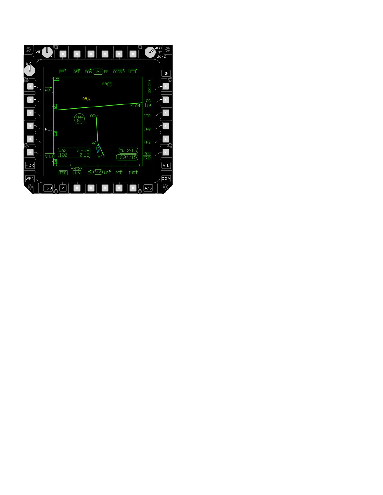
The TSD page, (fig 3-64) controls navigation subsystem
• Air Density Ratio
moding. Selecting the TSD subsystem button or the TSD
3.58 AN/APN-209 RADAR ALTIMETER (RADALT)
button from the MENU page calls up the TSD page which
The aircraft contains one Radar Altimeter. The Radar Al-
integrates various navigation status windows, graphic
timeter consists of a receiver/transmitter and antennas
symbols, and control selections.
Use or disclosure of this information is subject to the restriction(s) on the title page of this document.
Change 3
3-71
TM 1-1520-251-10
• B6
THRT Page button
3.61.1 TSD Map Functionality. The TSD can be con-
figured for 2 different phases of the mission.The NAV
phase provides enroute information and the, ATK phase
provides information pertaining to the battle area Refer to
the chart in paragraph 3.69 for a complete list of items dis-
played in each phase.
The NAV phase provides enroute information and the,
ATK phase provides information pertaining to the battle
area Refer to the chart in paragraph 3.69 for a complete
list of items displayed in each phase.
3.61.2 RPT Page Button. Selection of the RPT button
will cause the report page to be displayed.
3.61.3 ASE Page Button. Selection of the ASE button
will cause the ASE page to be displayed. Refer to chapter
4A.
LBA0423A
3.61.4 PAN Page Button. Selection of the PAN button
will cause the PAN page to be displayed.
Figure 3-64. TSD Page
3.61.5 Present Position (PP) Button. Selecting the
• T1
RPT Page button
PP button commands display of the present position sta-
• T2
ASE Page button
tus window. The status window includes:
• T3
PAN Page button
• Latitude
• T4
PP button
• Longitude
• T5
COORD button
• UTM coordinate data
• T6
UTIL button
• Current Mean Sea Level (MSL) elevation of the
• L1
ADF button
terrain below the aircraft
• L2
HDG button
3.61.6 COORD Button. Selection of the COORD but-
• L3
PSN button
ton will cause the COORD page to be displayed.
• L4
REC button
• L5
JAM button
3.61.7 TSD UTIL Button. Selection of the UTIL button
will cause the UTIL page to be displayed.
• L6
SHOW button
• R1
ZOOM button
3.61.8
ZOOM Button. Selecting the ZOOM button
• R2
SC (Scale) button
magnifies the current map scale by a factor of 20 percent
about the ownship symbol. The size of the map display
• R3
CTR button
symbols do not change when ZOOM is selected.
• R4
CAQ (Cursor Acquisition) button
• R5
FRZ button
3.61.9 Map Scale (SC) Button. The map scale at sys-
tem power-up is 1:250K. The SC button allows the crew to
• R6
ACQ button
select between the four map scales: 1:50K, 1:100K,
• B2
PHASE button
1:250K, and 1:500K.
• B3
ZN button
3.61.10 Center (CTR) Button. Selecting the CTR but-
• B4
WPT Page button
ton toggles the ownship symbol to the center or lower one
• B5
RTE Page button
third of the map area on the display.
Use or disclosure of this information is subject to the restriction(s) on the title page of this document.
3-72
TM 1-1520-251-10
3.61.11 Cursor Acquisition (CAQ) Button. The CAQ
UTM coordinates for the selected point. A UPT button is
button allows for rapid selection of stored coordinate point
displayed when the new coordinates have been entered.
symbols, FCR detected target symbols, or RFI detected
threat symbols as the acquisition source from the TSD.
b. Position Update (UPT) Button. The UPT but-
RFI detected threats are only selectable when the se-
ton is used to command the EGIs to update their present
lected sight is TADS or Helmet Mounted Display (HMD).
position with the new coordinates entered using the POSI-
Selecting the CAQ button freezes the TSD map.
TION button.
3.61.12 Acquisition (ACQ) Button. The ACQ button
3.61.17 Receive (REC) Button. The REC button is
provides the ability to select the desired acquisition
used to receive the most recent IDM message that can be
source for the selected sight. See Chapter 4 for descrip-
received from the TSD page. The REC button is only dis-
tion of selections.
played when a message is in the IDM buffer. The REC
button is displayed in WHITE. When the last message re-
3.61.13 Freeze (FRZ) Button. Selection of the FRZ
ceived is one of the following, selecting this button will
button provides the ability to freeze the desired map dis-
store the message in the appropriate current mission file
play or return to an active display.
location without being identified.
• WPT/HZD
3.61.14 ADF Page Button. Selection of the ADF but-
• CTRLM
ton will cause the ADF page to be displayed.
•
TGT/THRT
• FCR TGT RPT
3.61.15 Heading (HDG) Button. The system displays
the HDG button when the primary EGI estimated heading
• BDA RPT
error is greater than 10 degrees. The HDG button is dis-
• PF ZONE
played in WHITE. Selecting the HDG button brings up the
• NF ZONE
HEADING button which is used to enter a new heading.
•
PF/NF ZONE
a. HEADING Button. The HEADING button is used
• RFHO
to enter the correct aircraft heading through the KU. An
• PP RPT
UPT button is displayed when the new heading has been
• FARM RPT
entered.
When the last message received is one of the following,
b. Heading Update (UPT) Button. The UPT button
selecting this button will automatically switch to the RCVD
is used to command the system to update both EGIs with
MSG page of the ATHS-TACFIRE. See figure 3-60 in
the aircraft heading entered with the HEADING button.
paragraph 3.53.3 for more information.
• FREE TEXT T
3.61.16 PSN Button.
The PSN button is displayed in
• BDA RPT T
WHITE. The system displays the PSN update button
when the estimated radial position error from the primary
• FARM RPT T
EGI is greater than 50 meters (0.050 Km). Selecting PSN
• PP QUERY T
will cause the POSITION button to be displayed.
• PP RPT T
• MAYDAY T
a. POSITION Button. The POSITION button is
used to enter the correct LAT/LONG or UTM coordinates
• MOVE CMD T
through the KU. Selecting the POSITION button will arm
• SPOT RPT T
the KU for entry of the new coordinates. The system will
• NEG SPOT T
accept LAT/LONG or UTM coordinate data, with or with-
• AIR RQST T
out the entry of the datum. If a coordinate is entered with-
out a datum, then the system assumes whatever the cur-
• ARTY INTL T
rent datum being flown is what the coordinate being
• ARTY RQST T
entered is in. Rather than entering the coordinates using
• MSG 2 OBS T
the KU, the crew can also select any coordinate point
• OBSRV RDY T
(waypoint, hazard, control measure, or stored target/
threat) using the cursor control. The system loads the
• ATHS MSG
Use or disclosure of this information is subject to the restriction(s) on the title page of this document.
3-73
TM 1-1520-251-10
3.61.18 Radar Jammer (JAM) Button. This button is
3.61.26 Aircraft Heading Status Window. The aircraft
only displayed when the jammer is turned ON. Selecting
heading status window is displayed at the top center of the
the JAM button toggles the radar jammer between STBY
format
and OPER.
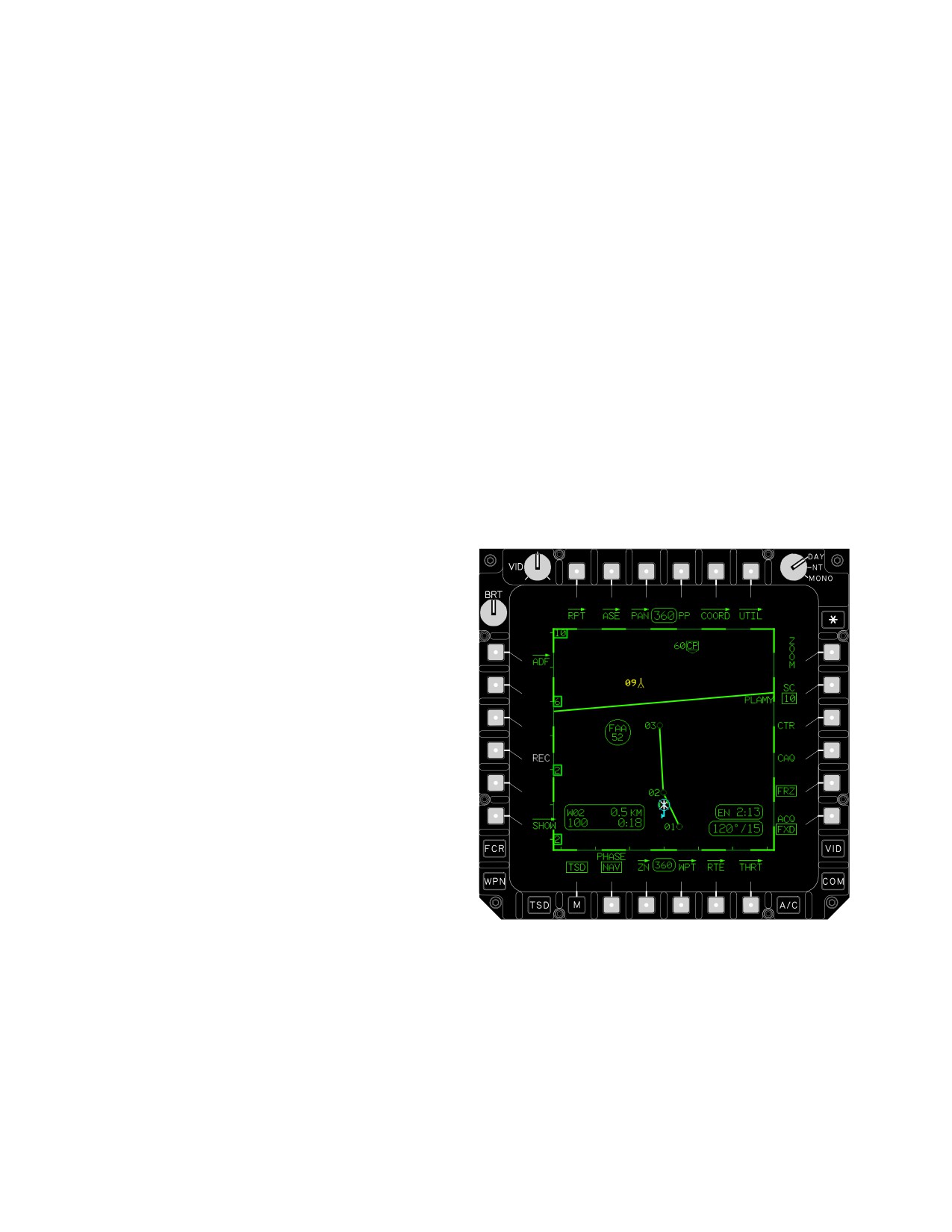
3.61.27 Map Frozen Cue. The TSD map frozen cue
3.61.19 SHOW Button. Selection of the SHOW button
(fig 3-65) is a bold dashed line displayed around the map
will cause the SHOW page to be displayed.
border and a frozen ownship symbol at the centered/ de-
centered location, to indicate the map is not in a dynamic
3.61.20 PHASE Button. The PHASE button allows the
state. The dynamic ownship (CYAN), TADS footprint, and
crew to select either NAV (Navigation) or ATK (Attack)
FCR footprint will continue to move about the viewable
mode of operation. The mode of operation affects which
area, and the heading and waypoint information will pro-
information is presented on the TSD page and which op-
vide continuous real - time situational awareness.
tions are available on the SHOW page.
The following control selections cause the map to freeze:
NOTE
3.61.21 Zone (ZN) Page Button. Selection of the ZN
button will cause the zone page to be displayed.
TSD Map Frozen Cue is in place until Prima-
ry EGI alignment is complete.
3.61.22 Waypoint (WPT) Page Button. Selection of
• ZN page
the WPT button will cause the waypoint page to be dis-
played.
• CAQ button
• FRZ button
3.61.23 Route (RTE) Page Button. Selection of the
• PAN page buttons
RTE button will cause the route page to be displayed.
3.61.24 Threat (THRT) Page Button. Selection of the
THRT button will cause the threat page to be displayed.
3.61.25 Next Waypoint Status Window. The next
WAYPOINT status window is displayed in the lower left
area of the MPD. It is displayed in the NAV mode to pro-
vide information regarding the current active waypoint be-
ing directly flown to or the current flight route being flown.
The status window includes the following:
a. Next Waypoint Letter and Number. The next way-
point letter will be a “W”, “H”, or “C”. The next waypoint
number will be a number from 1 to 50 if the next waypoint
letter is a “W” or “H”, or a number from 51 to 99 if the next
waypoint letter is a “C.”
b. Distance To Go. The distance to go will be dis-
played in either kilometers or nautical miles based on the
unit setting on the FLT SET Page.
LBA2607A
c. Time To Go. The time to go will display either
Figure 3-65. TSD Map Frozen Cue
minutes and seconds if the time is <5 minutes, or hours
and minutes if the time is >5 minutes and >10 hours.
3.61.28
Next Waypoint Heading Status Window. The
d. Ground Speed. If the current calculated ground
next waypoint heading status window is displayed at the
speed is valid, it will be displayed in kts.
bottom center of the format.
Use or disclosure of this information is subject to the restriction(s) on the title page of this document.
3-74
TM 1-1520-251-10
3.61.29 Endurance Status Window. The EN status
3.62.4 Waypoint/Hazard
(WPTHZ) Icon. A WPTHZ
window is displayed in the lower right area of the format to
icon indicates the location, type and number of a waypoint
indicate total fuel endurance time at the present power
or hazard stored in the waypoint/hazard coordinate data
setting. Calculations shall include fuel in internal and aux-
files. Hazard icons are displayed in YELLOW. The way-
iliary tanks
(if installed). The EN label is displayed in
point/hazard number is displayed to the left of the way-
WHITE and flashes when the total fuel endurance is 20
point or hazard symbol. The waypoint/hazard number will
minutes or less.
be displayed inverse video when the following conditions
exist:
3.61.30
Wind Direction/Velocity Status Win-
dow. Wind direction and velocity is selectively displayed
a. When on the RTE page with the ADD button se-
in the NAV and ATK phases, in the lower right corner of
lected and the waypoint/hazard is the currently selected
the TSD. If wind speed is less than 5 knots, the label
waypoint/hazard.
CALM is displayed. When Nr is less than 50% and wind
b. When on the RTE page with the RVW button se-
speed is greater than 45 knots, wind speed is displayed in
lected and the waypoint/hazard is the currently selected
YELLOW.
waypoint/hazard.
3.61.31 Map Border Symbol. The map border symbol
c. When on the WPT page with the RVW or EDT but-
defines the map area on the TSD page and is approxi-
ton selected and the waypoint/hazard is currently the ac-
mately 5 by 5 in. square. Range ticks are displayed along
tive waypoint/hazard.
the left and bottom of the map border symbol. In addition,
numeric range values are displayed at every other range
d. When on the WPT page with the DEL or XMIT but-
tick along the inside left border beginning at the bottom
ton selected and the waypoint/hazard is currently the ac-
range tick. Although the map border symbol remains
tive waypoint/hazard.
constant in size and location on the page, the range tick
The valid range for the waypoint/hazard numbers is 1 to
locations and numeric values change according to the
50. There are 6 different waypoint symbols and 4 hazard
states of the map scale button, the ZOOM button, the
symbols that can be displayed on the TSD (App D). Way-
CTR button, and the KM/NM button on the FLT page.
points on the TSD page are always displayed in both
phases. Hazard symbols are always displayed in the NAV
3.62 TSD MAP SYMBOLOGY
phase, but are selectable in the ATK phase via the SHOW
The following paragraphs describe various symbols and
page. When the waypoint/hazard files are loaded from the
the conditions under which they appear within the TSD
DTC, a number is stored for each data file saved that indi-
map area. The symbols are displayed in geographic fidel-
cates the “SAFE SET” for that loaded DTC file (maximum
ity according to the map scale selected. The map is head-
of 25 points). This prevents overwriting a ”SAFE SET” file
ing-up oriented and the display of any particular symbol
via normal storing procedures. Data can be deleted from
depends upon the PHASE selection and the state of the
SAFE SET via the DEL button or changed from within the
control selections on the SHOW page. See paragraphs
ownship via the EDT button. An incoming IDM message,
3.68.1 and 3.68.2.
if elected to be stored, can also overwrite a SAFE SET.
3.62.1
Ownship Symbols. The dynamic ownship
For example: If 10 waypoints/hazards are loaded through
symbol is displayed in CYAN and represents the helicop-
the DTC, and then point number 11 is stored after DTC
ter position within the dynamic mapping area. Specifically,
loading, the SP will not attempt to store a waypoint/hazard
the dot in the center of the ownship symbol depicts the
with an index less than 11. If the DP requests to store a
present position of the helicopter relative to the map sym-
point with an index of less than 11, then the SP will do this.
bols. The frozen ownship symbol is displayed in WHITE,
3.62.5 Control Measure (CTRLM) Icon. A CTRLM
with stopped rotors, and remains at the centered or de-
icon indicates the location, type and number of a control
centered position as selected.
measure stored in the coordinate data files. Friendly con-
3.62.2 Route Line. The route line is a straight line con-
trol measure icons are displayed in CYAN and enemy
necting the points (waypoints, hazards, and control mea-
control measure icons are displayed in RED. The control
sures) in the current route. The route line becomes partial
measure type and number is usually displayed within the
intensity when the active destination point is other than
CTRLM icon. The point number will be displayed in in-
the next point in the current route.
verse video when the point is the currently selected or ac-
tive point. The valid range for the point numbers is 51 to
3.62.3
Direct-To Line. The route direct-to line is a
99. Present position responses are stored in C93 through
straight line indicating a direct course to the selected
C99 and are displayed on the TSD with the helicopter
point.
icon. (Appx D).
Use or disclosure of this information is subject to the restriction(s) on the title page of this document.
3-75
TM 1-1520-251-10
3.62.6 Threat/Target (THRT/TGT) Icon. The THRT/
feedback on the map. The TADS footprint symbol displays
TGT icon indicates the location/number of a target or the
when TADS is the selected sight for the CPG or either
location/type of a threat stored in the coordinate data files.
crewmember has linked TADS to his current selected
THRT/TGT icons are displayed in RED. When the THRT/
sight.
TGT icon is a stored target, the icon is a T followed by the
target file number. When the THRT/TGT icon is a pre-
3.62.12 FCR Footprint Symbol. The FCR footprint
planed target/threat, the icon may be a symbol with a 2
symbol is a perimeter of partial intensity GREEN lines
digit identifier. The target/threat number will be displayed
which originates at the ownship symbol to indicate the
inverse video when the threat has been selected on the
FCR scan footprint or FCR scan azimuth and area of cov-
THRT page in the RVW, EDIT, DEL or XMIT modes.
erage within the map area. The partial intensity GREEN
lines change to full intensity WHITE lines when the FCR is
The valid range for the target/threat numbers is 1 to 51
scanning. An azimuth tick displays at the midpoint of the
The FCR target coordinate data is stored in T50 when the
arc within the FCR footprint symbol to provide precise azi-
CAQ button is used to select an FCR target symbol. The
muth feedback on the map. The FCR footprint symbol dis-
coordinate data for the ATHS air fire mission target is
plays when FCR is the selected sight for either crewmem-
stored in T51. T51 does not exist on the DTU and is not
ber or either crewmember has linked FCR to his current
transmitted in any of the AFAPD messages. The T51 tar-
selected sight.
get cannot be edited nor can new targetas be added/
stored into T51 via the THRT page. The T51 ATHS TAR-
3.62.13 FCR Target Symbols. FCR target symbols
GET can be deleted when the HFMSN button is not
within the map area indicate target information detected
selected. The SAFE SET also applies to the targaets/
during an FCR scan burst. Two types of target symbols
threats file.
are displayed: FCR priority target symbols and FCR total
target symbols. FCR priority target symbols representing
3.62.7 ATHS TARGET Icon. The ATHS TARGET icon
moving targets may move due to updated target position
is a large octagonal white icon. The ATHS TARGET icon
from the radar. The target placement within the map area
is displayed around T51 when HFMSN is selected.
following each scan will indicate the direction and appar-
ent rate of movement of those targets. The high priority
3.62.8 LINE Icon. The LINE icon indicates the location
FCR targets display full intensity YELLOW; lesser priority
and name of a geographic line stored in the coordinate
targets are partial intensity YELLOW and half size (maxi-
data files. The designated label indicates the type of LINE
mum targets displayed is 256). When the TSD 1:250K
icon.
map scale is selected, high priority FCR targets display as
full intensity three pixel squares, and low priority FCR tar-
3.62.9
AREA Icon. The AREA icon indicates the
gets display as partial intensity three pixel squares. When
boundary location, label, and number of a target engage-
the TSD 1:500K map scale is selected, no FCR targets
ment area stored in the coordinate data files. The engage-
will be displayed. However, the partial intensity FCR foot-
print remains.
ment area label/number (EA##) of the AREA icon is at the
center point of the geographic area.
3.62.14 RFI Threat Icon Symbol. When a threat is de-
3.62.10 ASE Footprint Symbol. The ASE footprint
tected by the RFI, an RFI threat icon symbol is displayed
symbol is a partial intensity square border line within the
along the outside perimeter of the ASE footprint symbol
map border symbol providing a perimeter line or footprint
within the map area to indicate azimuth (relative direction)
which segregates RLWR (inside) and RFI (outside) threat
and threat type information on the TSD page. Friendly
symbols. It is automatically displayed on the TSD page
emitter icons are displayed in CYAN and enemy/gray
when a threat is detected by the RLWR.
threat icons are displayed in YELLOW. Stale threat icons
are displayed in partial intensity.
3.62.11 TADS Footprint Symbol. The TADS footprint
symbol is a partial intensity GREEN straight line which
3.62.15 RLWR Threat Icon Symbol. When a threat is
originates at the ownship symbol and changes in length
detected by the RLWR, a RLWR threat symbol is dis-
and azimuth to indicate TADS LOS positioning within the
played along the inside perimeter of the ASE footprint
map area. The partial intensity GREEN line changes to a
symbol within the map area to indicate azimuth (relative
full intensity WHITE line when TADS is lasing. An open
direction) and threat type information on the TSD page.
center crosshair symbol displays full intensity at the end of
Enemy/gray threat icons are displayed in YELLOW. Stale
the TADS footprint symbol to provide precise position
threat icons are displayed in partial intensity.
Use or disclosure of this information is subject to the restriction(s) on the title page of this document.
3-76
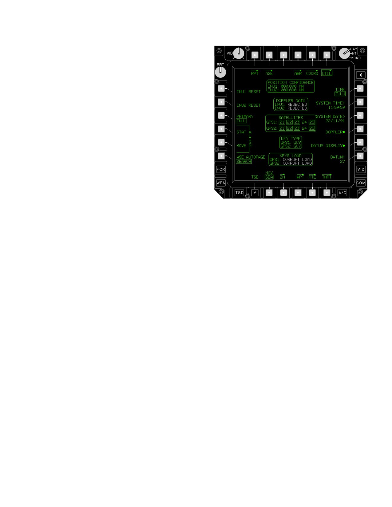
TM 1-1520-251-10
3.62.16 Shot - At Icon. This system stores target coor-
dinates in the coordinate data shot-at file each time a tar-
get is engaged (actual or simulated) with the Hellfire Mis-
sile system by the ownship in the ownship file. For RF
missile engagements, the coordinates of the NTS target
are stored to the shot-at file. For SAL autonomous missile
engagements (LRFD code = missile seeker code), the tar-
get coordinates stored are derived using the CPG’s sight
and range source regardless of which crewmember con-
ducts the engagement. For SAL remote missile engage-
ments (LRFD missile seeker code), the target coordi-
nates stored are those last stored in the shot-at file. If no
previous launches have occurred since power up, the lati-
tude, longitude, and altitude values stored to the shot-at
file will be all zeros. The shot-at icon is an X symbol with
no label or number. The X symbol will be on top of the tar-
get symbols if the target was engaged after the last scan,
otherwise it will be below target symbols. A total of 16
locations are available in the ownship file.
LBA2399
3.62.17 IDM Shot-At Icon. The IDM shot-at icon is a
Figure 3-66. TSD UTIL Page
partial intensity X symbol with no label or number. It repre-
sents locations where targets have been engaged by air-
The TSD UTIL page provides access to the following
craft other than the ownship. The IDM provides target
unique functions:
coordinates for storage in the coordinate data shot-at file
after being accepted by the crew. A total of 112 locations
• T6
TSD UTIL button
are available in the IDM shot-at file.
• L1
INU1 RESET button
• L2
INU2 RESET button
• L3
PRIMARY button
3.62.18 HSI Icon. The HSI icon is a Magnetic Compass
Rose which can be selectively displayed in the NAV and
• L4
ALIGN STATionary button
ATK phases. The HSI is always displayed on the ADF/
• L5
ALIGN MOVE button
ADF UTIL pages.
• L6
ASE AUTOPAGE button
• R1
TIME button
3.62.19 Waypoint Approach and Passage Adviso-
• R2
SYSTEM TIME button
ries. When neither crewmember has the dynamic map
• R3
SYSTEM DATE button
displayed, or the TSD displays are frozen, an advisory
• R4
DOPPLER button
message is displayed on the UFD when the aircraft is
• R5
DATUM DISPLAY button
within one minute of passing a waypoint or upon waypoint
passage.
• R6
DATUM button
• B2
Navigation Mode (NAV) button
3.63.1 INU1/2 RESET Button. The INU1/2 RESET but-
3.63 TSD (UTIL) PAGE
tons resets the INU1/2. It is primarily used when the data
from the INU is invalid or inaccurate.
The TSD UTIL page, (fig. 3-66) can be used to initiate
3.63.2
PRIMARY Button. The PRIMARY button is
navigational system alignments, reset the INUs, enable
used to select the active INU: INU1/2. The button state in-
the Doppler, select the datum for display, modify the cur-
dicates the active (primary) INU whether selected auto-
rent datum, and enter system time and date data. The
matically by the system or manually by the operator. It is
TSD UTIL page also provides both INUs position confi-
selectable only when both INUs are operational and equal
dence.
in status.
Use or disclosure of this information is subject to the restriction(s) on the title page of this document.
3-77
TM 1-1520-251-10
3.63.3
ALIGN STATIONARY (STAT) Button. The
3.63.9 DOPPLER Button. The DOPPLER button en-
ALIGN STAT button is displayed only when the state of
ables or disables the Doppler.
the NAV mode button is set to SEA and the primary and/or
secondary INU has a position from the GPS or has been
3.63.10 DATUM DISPLAY Button. The DATUM DIS-
manually entered and that it is ready to initiate a stationary
PLAY button enables diaplay of datum information within
navigation system alignment.
various status windows.
3.63.11 DATUM Button. The DATUM button allows
3.63.4 ALIGN MOVE Button. The ALIGN MOVE but-
entry of a new datum in place of the default datum entered
ton displayed only when the state of the NAV mode button
at the mission planning station. If the pilot enters a D using
is set to SEA and the primary and/or secondary INU has a
the KU, the system returns to the default datum and auto-
position from the GPS or has been manually entered and
matic datum updates, based on the current waypoints and
that it is ready to initiate a moving navigation system align-
their datums in the current route being flown.
ment. These are only displayed when on the ground in
SEA mode.
NOTE
When the INU is reset or power is applied to
3.63.5
ASE AUTOPAGE Button. The ASE AUTO-
the INU, the MPD will not display symbols
PAGE button is used to select the state or condition of an
that use INU information until the INU deter-
acquiring threat system which causes autopaging of
mines that its data is valid.
threat warning information. The ASE AUTOPAGE is
crewstation independent. The available selections are:
3.63.12 Navigation (NAV) Mode Button. The NAV
• SEARCH
mode button selects the navigation mode: (LAND or SEA)
The primary System Processor (SP), upon generator
• ACQUISITION
power up, automatically controls initialization and align-
ment of the EGIs of the aircraft. Upon system power up,
• TRACK
the last NAV mode stored LAND or SEA, at power down
• OFF
will be selected automatically by the SP. The flight crew
should confirm the correct moding of LAND or SEA
(SEA-Stationary or Moving) for the initialization/align-
3.63.6 TIME Button. The TIME button sets the display
ment process based on the current aircraft configuration.
mode of time to LOCAL or ZULU.
After takeoff, (in-flight) the Navigation Mode switch is used
to select LAND or SEA using the criteria of where the air-
3.63.7
SYSTEM TIME Button. The SYSTEM TIME
craft is to be primarily operated for the mission. The LAND
button sets the current LOCAL or ZULU time. The ZULU
mode is used when operating primarily over terrain. The
time must be entered before the LOCAL time. When a
SEA mode is used when operating primarily over water.
ZULU System Time is entered, the system processor sets
When the LAND or SEA mode selection is made in-flight,
its clock to the entered time, and sends this time to the re-
there will be no apparent change to the flight crew (with
spective primary and secondary EGIs if their respective
the exception of the displayed LAND or SEA mode) but
GPS is not tracking enough satellites. To determine if the
the navigation system will change the weighting of the
GPS used the time, monitor the Satellite Status window. If
Doppler velocity data to provide the best navigational ac-
the time entered is used, the respective GPS Satellite ID
curacy (most significantly during degraded navigation
numbers in the Satellite Status window, will momentarily
modes).
blank, then reappear.
3.63.13
POSITION CONFIDENCE Status Win-
3.63.8 SYSTEM DATE Button. The SYSTEM DATE
dow. The POSITION CONFIDENCE status window in
button sets the current date. When a system date is en-
the upper area of the page presents position confidence
tered, the system processor sets its Date to the entered
status for INU1 and INU2. This value represents the 95%
system date, and sends this date to the respective primary
probable radial position error of the position estimate of
and secondary EGIs if their respective GPS is not tracking
latitude and longitude. It is displayed in WHITE when the
enough satellites. To determine if the GPS used the date,
value is greater than 50 meters, FAILED, or when the INU
monitor the Satellite Status window. If the date entered is
is not installed.
used, the respective GPS Satellite ID numbers in the Sat-
ellite Status window, will momentarily blank, then reap-
3.63.14 DOPPLER DATA Status Window. The DOP-
pear.
PLER DATA status window provides the Doppler aiding
Use or disclosure of this information is subject to the restriction(s) on the title page of this document.
3-78
Change 2
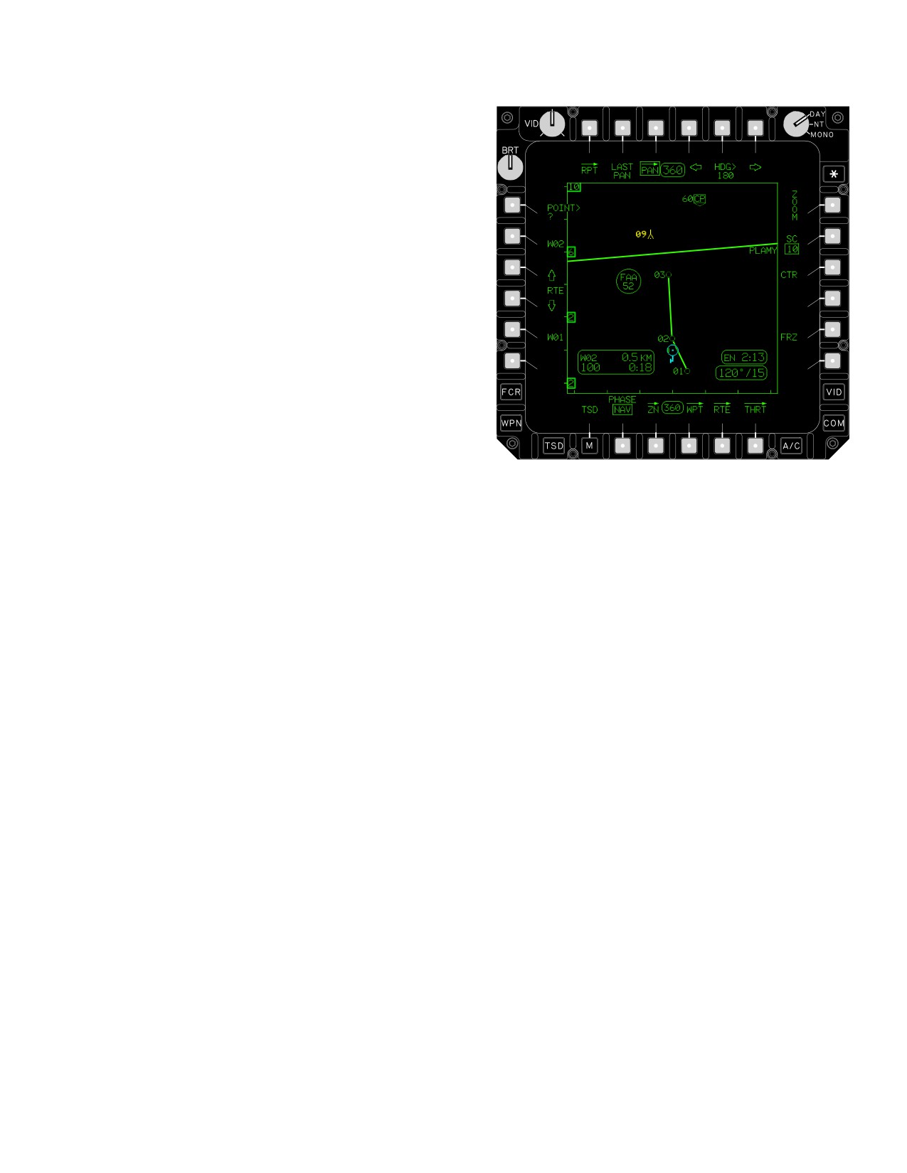
TM 1-1520-251-10
status of INU1 and INU2: USED, REJECTED (WHITE), or
MEMORY (WHITE).
3.63.15 SATELLITE Status Window. The SATELLITE
status window provides the satellite number(s) that the
EGI is attempting to track. The box indicates that a partic-
ular satellite is being tracked.
3.63.16 KEY TYPE Status Window. The KEY TYPE
status window provides an indication to the crewmember
what type of key has been loaded into GPS receivers 1
and 2. If a Group Unique Variable (GUV) is loaded this sta-
tus window will show GUV. If a Weekly key is loaded the
status window will be blank, but the GPS keys status win-
dow will indicate LOADED.
LBA3017
3.63.17
KEYS LOAD Status Window. The KEYS
Figure 3-67. PAN Page
LOAD status window provides the current state of the
GPS keys loaded into GPS receivers 1 and 2. The follow-
• T2
LAST PAN button
ing states are valid for display:
• T3
PAN Page button
• T4
Left Pan HDG Arrow
• ERASE FAIL (WHITE)
• T5
Pan HDG Data Entry button
• T6
Right Pan HDG Arrow
• NONE (WHITE)
•
L1
Pan POINT button
• L2
Next WPT in RTE button
• CORRUPT LOAD (WHITE)
•
L3
Forward in RTE Arrow button
• L4
Back in RTE Arrow button
• VALID
•
L5
Last WPT in RTE button
• R1
ZOOM button
• INCORRECT (WHITE)
• R2
SC (Scale) button
• R3
CTR button
• VERIFIED
• R5
FRZ button
• LOADED
3.64.1
LAST PAN Button. Selection of the LAST PAN
button returns the live map to the last panned location and
heading.
3.64 PAN PAGE
3.64.2 PAN. Selection of the PAN button will cause the
PAN page to be displayed. Additionally, the cursor is ac-
tive for selection of a pan destination. A cursor footprint
the size of the map and centered around the cursor can be
The PAN page ( fig 3-67) gives the crew a limited TSD
used to rapidly pan about the display.
map scrolling capability. The TSD may be scrolled along
the current route, to a coordinate data file location, UTM/
3.64.3 HDG Left/Right Arrow Buttons. Pressing the
LAT - LONG coordinate or to a cursor selected point.
left/right arrow buttons momentarily changes the pan
Use or disclosure of this information is subject to the restriction(s) on the title page of this document.
3-79
TM 1-1520-251-10
heading in 1 degree increments. Pressing and holding
the next waypoint or back(down) to the previous waypoint
changes the heading at 40 degrees per second.
in a single step or continuous at 2 Hz rate if pressed and
held.
3.64.4 HDG Button. The HDG button is used for data
entry of the pan heading.
3.64.7 Forward/Backward in RTE Button. Selecting
the RTE button momentarily pans forward (up) to the next
3.64.5 POINT Button. Selection of the POINT button
waypoint or back(down) to the previous waypoint in small
allows entry of UTM/LAT - LONG coordinate or a coordi-
increments or continuous at 20 Hz if pressed and held.
nate data file point number for pan destination.
3.64.8 Freeze (FRZ) Button. Selection of the FRZ but-
3.64.6 Next/Last WPT in RTE Buttons. Selecting the
ton provides the ability to freeze the desired map display
Next/Last WPT buttons momentarily pans forward (up) to
or return to an active display.
Use or disclosure of this information is subject to the restriction(s) on the title page of this document.
3-80
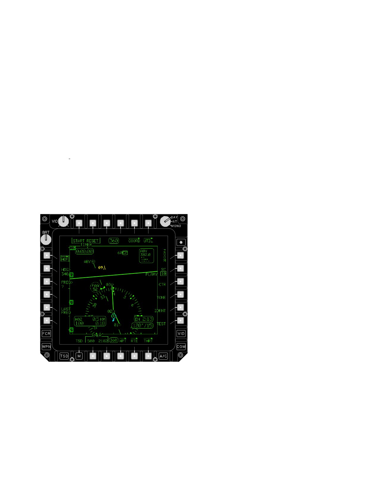
TM 1-1520-251-10
3.65 ADF PAGE
• L3
NDB FREQUENCY (FREQ) button
• L5
LAST FREQUENCY (LAST FREQ)
NOTE
•
R1
ZOOM button
ADF MODE, FREQ, TEST, LAST, TONE,
• R2
SCALE button
IDENTIFY, EMER 500, EMER 2182 options
will not be displayed if the ADF system is not
• R3
CTR button
enabled.
• R4
TONE button
• R5
IDENT button
The ADF page (fig 3-68 ) is used to control the ADF Sys-
• R6
TEST button
tem and provide the symbology necessary to perform
ADF navigation. A compass rose, heading select indicator
• B2
EMERgency 500 Tune button
(with inverse heading), and Non Directional Beacon iden-
• B2
EMERgency 2182 Tune button
tifier/frequency status are displayed over the moving map
display. The next WAYPOINT status window is displayed
3.65.1
TIMER START/STOP Button. The TIMER
in the lower left portion of the page. The ENDR and WIND
START/STOP button is used to start/stop the digital timer
status windows are displayed in the lower right portion of
readout.
the page. The moving map is always dynamic unless the
INU data is invalid. NDB symbols whose free text match
3.65.2
TIMER RESET Button. The TIMER RESET
one of the presets can be selected from the ADF and ADF
button is used to reset the digital timer readout displayed
UTIL. When selected the the ADF will be tuned to the
in the TIMER STATUS WINDOW.
matching preset.
3.65.3 HDG Button. The HDG button is used to set the
numeric magnetic heading value for the Heading Select
Indicator. The HDG button is only displayed if the INU is
operational.
3.65.4 NDB FREQ (Frequency) Button. FREQ button
is used to manually set the numeric value of a NDB fre-
quency or commercial broadcasting station.
3.65.5 LAST FREQ (Last Frequency) Button. LAST
FREQ button is used to toggle between the current and
previously tuned NDB frequency or commercial broad-
casting station.
3.65.6 TONE Button. Selecting the ADF TONE button
causes the normal audio to be replaced by the 1000 Hz
tone for continuous wave (CW) operation.
3.65.7 IDENTIFY Button. Selecting the ADF IDENTI-
FY button causes the normal audio output to be filtered for
clarity.
LBA3018
3.65.8 TEST Button. The TEST button is used to test
Figure
3-68.
ADF Page
the ADF System circuits and strength of the station signal
received. Selecting the TEST button causes the ADF
Bearing Pointer to momentarily shift approximately 90°
The ADF page contains the following unique buttons:
right from the present bearing for several seconds then
• T1
TIMER START/STOP button
return to the original bearing. A faulty system circuit could
possibly cause the ADF Bearing Pointer to shift to a value
• T2
TIMER RESET button
other than approximately 90° right. The rate at which the
• T6
ADF UTIL button
ADF Bearing Pointer returns to the original bearing indi-
• L2
Selected Heading (HDG) button
cates the relative strength of the station signal received.
Use or disclosure of this information is subject to the restriction(s) on the title page of this document.
3-81
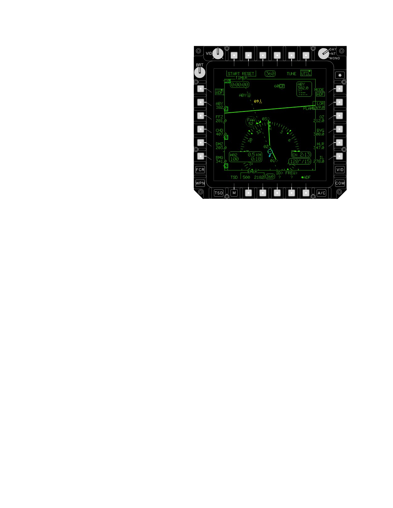
TM 1-1520-251-10
3.65.9 EMER (Emergency) 500/2182 Buttons. The
EMER buttons are used to rapidly tune the ADF receiver
to the international distress frequencies.
3.65.10 Timer Status Window. The timer status win-
dow is used to display the elapsed time of the timer. The
window has a format of H:MM:SS and a range of 0:00:00
to 9:59:59.
3.65.11 NDB Status Window. The NDB status window
displays in the upper right area of the ADF page to indi-
cate the current frequency, station identifier letters, and
morse code to which the the ADF system is tuned. The
station identifier letters and morse code are displayed
only when there is an identifier associated with the tuned
frequency or the tuned frequency is an emergency fre-
quency. If the frequency is invalid, it will be displayed
WHITE.
3.65.12 Compass Rose. The circular arrangement of
LBA3019
tic marks (compass rose) rotates about a point to provide
the instantaneous magnetic heading of the helicopter. The
Figure 3-69. ADF UTIL Page
compass rose is constructed with tic marks of three sizes:
long tics for 30° increments, medium tics for 10° incre-
The ADF UTIL page contains the following unique but-
ments, and short tics for 5° increments. Cardinal point
tons:
heading values are displayed within the the compass rose
and remain upright as the compass rose rotates on the
• T5
TUNE button
page. The compass rose is placed at either the centered
• L2 - L6
ADF PRESET buttons
or decentered position based on current selection of the
CTR button.
• R1
ADF MODE button
• R2 - R6 ADF PRESET buttons
3.65.13
ADF Bearing Pointer. The ADF bearing
• B4
ADF Preset Identifier (ID) button
pointer is displayed from the edge of the magnetic com-
pass rose, through the ownship, to the edge of the display
• B5
ADF Preset Frequency (FREQ) button
to indicate magnetic bearing of the current signal being re-
• B6
ADF button
ceived by the ADF system.
3.66.1 TUNE Button. The NDB preset TUNE button is
used to tune the ADF receiver to the frequency of the se-
3.65.14 Heading Select Indicator. The heading select
lected ADF preset station button.
indicator is displayed on the periphery of the magnetic
compass rose to indicate the magnetic heading value
3.66.2 ADF Preset Buttons. The ADF preset buttons
entered at the HDG select button. A heading bug recipro-
are used to select specific ADF preset stations for tuning
cal is also displayed on the periphery of the compass
or editing.
rose.
3.66.3 MODE Button. Selecting the ADF MODE button
3.66 ADF UTILITY (UTIL) PAGE]
displays ANT.
The UTIL page (fig 3-69 ] ) is used to provide access to the
3.66.4 ID Button. The NDB preset identifier ID button is
stored preset ADF frequencies and utility selections. The
used to enter the NDB station identifier letters for the se-
presets can be edited or tuned based on crew inputs.
lected ADF preset button.
Use or disclosure of this information is subject to the restriction(s) on the title page of this document.
3-82

TM 1-1520-251-10
3.66.5
FREQ Button. The NDB preset frequency
Table 3-6. Abbreviation Listing Page 1 Mode
FREQ button is used to enter the NDB station frequency
value for the selected ADF preset button.
3.66.6 ADF Button. Selecting the ADF button alter-
nately toggles the ADF System between enabled and dis-
Abbreviation Name
ID
abled.
WAYPOINTS
3.67 ABBREVIATION (ABR) PAGE
Comm Check Point
CC
The ABR page, (fig 3-70), a view only page, provides a list
Landing Zone
LZ
of the correct two-letter identifications for a specific way-
Passage Point
PP
point, hazard, control measure, target, or threat. The ab-
breviation page also includes the two-digit identifier for
Release Point
RP
each of the datums associated with its spheroid.
Start Point
SP
NOTE
Waypoint
WP
There are no unique buttons on the ABR
page.
HAZARDS
Tower over 1000 (YELLOW)
TO
Tower Under 1000 (YELLOW)
TU
Wires Power (YELLOW)
WL
Wires Tele/Elec (YELLOW)
WS
GENERAL CTRLM
Air Control Point
AP
Airfield General
AG
Airfield Instrum
AI
Airfield Lighted
AL
Arty Fire Pt 1
F1
Arty Fire Pt 2
F2
Assembly Area
AA
LBA1927
Battalion
BN
Battle Position
BP
Figure 3-70. ABR Page
Bridge or Gap
BR
All available abbreviations are listed in tables 3-6 through
Brigade
BD
3-13 in their appropriate page mode.
Use or disclosure of this information is subject to the restriction(s) on the title page of this document.
Change 1
3-83
TM 1-1520-251-10
Table 3-7. Abbreviation Listing Page 2 Mode
Table 3-8. Abbreviation Listing Page 3 Mode
ABBREVIATION NAME
ID
ABBREVIATION NAME
ID
Chemical Friend (CYAN)
CF
Checkpoint
CP
Decon Friend (CYAN)
DF
Company
CO
Engineers Friend (CYAN)
EN
Corps
CR
ElecWar Friend (CYAN)
FW
Division
DI
Growth CTRLM FR1 (CYAN)
Z1
FARP Fuel Only
FF
Growth CTRLM FR2 (CYAN)
Z2
FARP Ammo Only
FM
Growth CTRLM FR3 (CYAN)
Z3
FARP Fuel/Ammo
FC
Fixed Wing Friend (CYAN)
WF
Forwd Assemb Area
FA
Field Arty Friend (CYAN)
FL
Grnd Lite/Sm Town
GL
Heli Attack Frien (CYAN)
AH
Holding Area
HA
Heli Genrl Frien (CYAN)
FG
IDM Subscriber
ID
Hospital Friend (CYAN)
HO
NBC Area
NB
Infantry Friend (CYAN)
FI
NDB Symbol
BE
Mech Infantry Fr (CYAN)
MI
Railhead Point
RH
Medical Friend (CYAN)
MD
Regiment/Group
GP
TOC Friend (CYAN)
TF
US Army
US
Unit ID Friend (CYAN)
FU
FRIENDLY CTRLM
ENEMY CTRLM
ADU Friendly (CYAN)
AD
Air Assault Enemy (RED)
ES
Air Assault Frien (CYAN)
AS
Air Cavalry Enemy (RED)
EV
Air Cavalry Frien (CYAN)
AV
Air Defense Enemy (RED)
ED
Airborne Friend (CYAN)
AB
Airborne Enemy (RED)
EB
Armor Friend (CYAN)
AM
Armor Cav Enemy (RED)
EC
Armor Cav Friend (CYAN)
CA
Armor Enemy (RED)
AE
Av Maint Friend (CYAN)
MA
Av Maint Enemy (RED)
ME
Use or disclosure of this information is subject to the restriction(s) on the title page of this document.
3-84
TM 1-1520-251-10
Table 3-9. Abbreviation Listing Page 4 Mode
Table 3-10. Abbreviation Listing Page 5 Mode
ABBREVIATION NAME
ID
ABBREVIATION NAME
ID
ADU Growth 1
G1
Av Maint Enemy (RED)
ME
ADU Growth 2
G2
Chemical Enemy (RED)
CE
ADU Growth 3
G3
Decon Enemy (RED)
DE
ADU Growth 4
G4
Engineers Enemy (RED)
EE
ADU Spada
SD
Elec War Enemy (RED)
WR
ADU M1983
83
Field Arty Enemy (RED)
EF
ADU 2S6/SA - 13
S6
Fixed Wing Enemy (RED)
WE
Gun Air Defense
AA
Growth CTRLM EN1 (RED)
Z4
Gun Generic
GU
Growth CTRLM EN2 (RED)
Z5
Gun Marksman
MK
Growth CTRLM EN3 (RED)
Z6
Gun Sabre
SB
Heli Attack Enemy (RED)
EK
Gun Self Prop
GS
Heli Genrl Enemy (RED)
HG
Gun Towed
GT
Hospital Enemy (RED)
EH
Gun ZSU-23
ZU
Infantry Enemy (RED)
EI
Naval Systems
NV
Mech Infantry En (RED)
EM
SAM Blowpipe
BP
Medical Enemy (RED)
EX
SAM Bloodhound
BH
TOC Enemy (RED)
ET
SAM Chapparal
CH
Unit ID Enemy (RED)
EU
SAM Crotale
CT
SAM CSA-2/1/X
C2
PREPLANNED TGT/THRT
SAM Hawk
HK
ADU AMX - 13 (RED)
AX
SAM Javelin
JA
ADU Aspide (RED)
AS
SAM Patriot
PT
ADU Enemy (RED)
ED
SAM Redeye
RE
ADU Gepard (RED)
GP
SAM Rapier
RA
ADU Growth 1 (RED)
G1
SAM Roland
RO
SAM SA-1
1
SAM SA-2
2
SAM SA-3
3
SAM SA-4
4
SAM SA-5
5
SAM SA-6
6
Use or disclosure of this information is subject to the restriction(s) on the title page of this document.
3-85
TM 1-1520-251-10
Table 3-11. Abbreviation Listing Page 6 Mode
Table 3-12. Abbreviation Listing Page 7 Mode
ABBREVIATION NAME
ID
ABBREVIATION NAME
ID
BESSEL
BES
SAM SA-6 (RED)
6
Bukit Rimpah Indo
4
SAM SA-7 (RED)
7
Djarkarta Indo
6
SAM SA-8 (RED)
8
Gunung Segara
11
SAM SA-9 (RED)
9
Gunung Serindung
12
SAM SA-10 (RED)
10
Montjong Low Indo
23
SAM SA-11 (RED)
11
Tokyo Jap Kor Oki
40
SAM SA-12 (RED)
12
Tokyo Special
44
SAM SA-13 (RED)
13
SAM SA-14 (RED)
14
CLARK 1866
CL6
SAM SA-15 (RED)
15
Guam 1963
10
SAM SA-16 (RED)
16
Luzon
21
SAM SA-17 (RED)
17
NAD 27 ConUS
25
SAM SAMP (RED)
SM
NAD 27 Alaska Can
26
SAM SATCP (RED)
SC
Old Hawaii Maui
27
SAM Self Prop (RED)
SP
Old Hawaii Oahu
28
SAM Shahine/R440 (RED)
SH
Old Hawaii Kauai
29
SAM Starstreak (RED)
SS
Luzon Special
43
SAM Tigercat (RED)
TC
CLARK 1880
CL0
SAM Stinger (RED)
ST
Adindan
1
SAM Towed (RED)
SA
ARC 1950
2
SAM Unknown (RED)
U
Ghana
9
SAM Vulcan (RED)
VU
Liberia 1964
19
Radar Battl Surv (RED)
SR
Merchich
22
Radar TGT Acq (RED)
TR
Minna
24
RBS-70 (RED)
70
Sierra Leone 1960
32
Target Ref Point (RED)
TG
Voirol
41
EVEREST
EVE
Indian Thai Viet
16
Indian Special
42
Use or disclosure of this information is subject to the restriction(s) on the title page of this document.
3-86
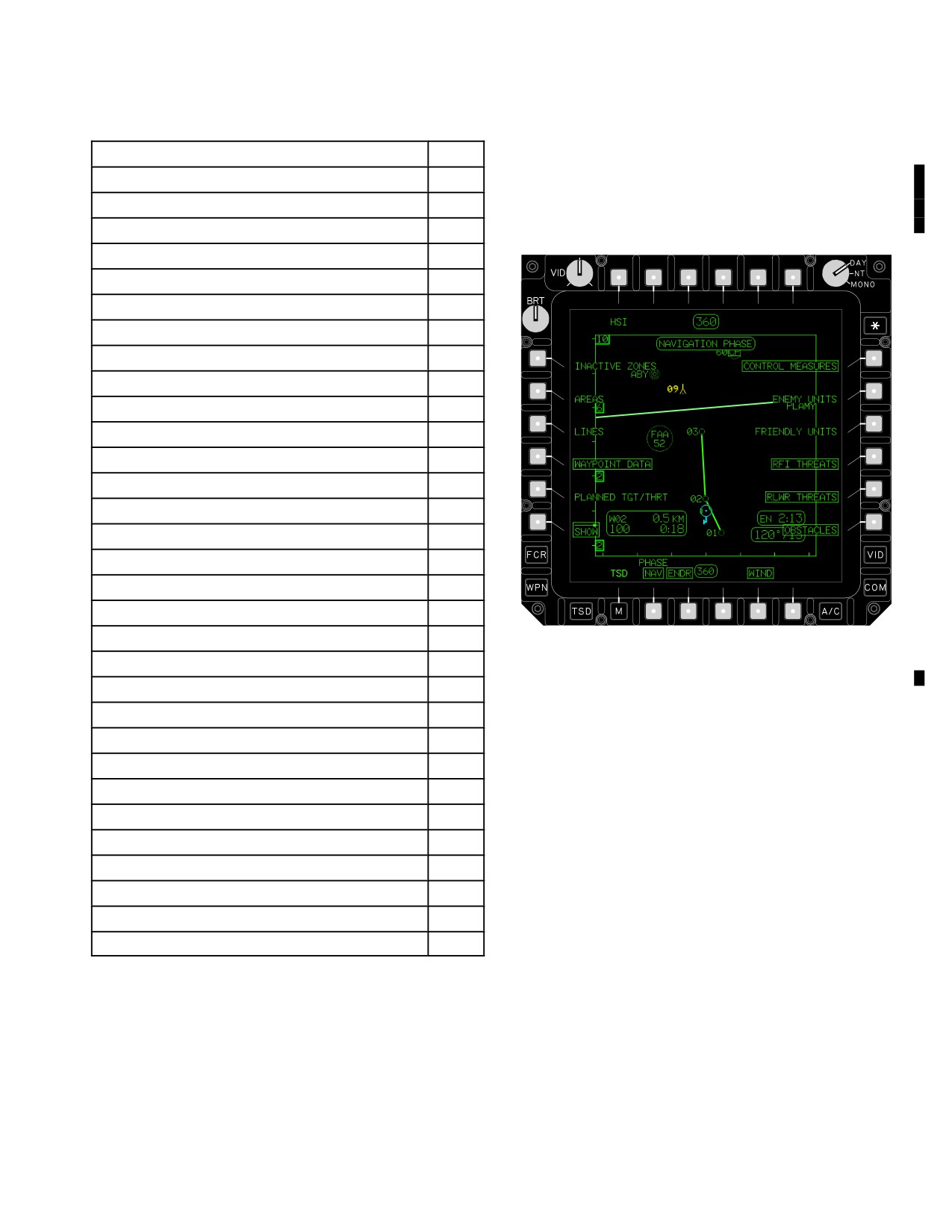
TM 1-1520-251-10
Table 3-13. Abbreviation Listing Page 8 Mode
Symbols will be displayed or removed as buttons are se-
lected if they are in the displayed map area.
ABBREVIATION NAME
ID
3.68.1 SHOW Page - NAV PHASE.
INTERNATIONAL
INT
Camp Area Astro
5
The NAV PHASE of the SHOW page (fig 3-71) is used to
European 1950
7
provide access to navigation data.
Geodetic Dat 1949
8
Herat North
13
Hjorsey
14
Hu-Tzu-Shan
15
Qornoq
31
Campo I Argentina
33
Chua A Paraguay
34
Corrego A Brazil
35
Prov 1956 S Amer
36
Yacare Uraguay
37
Tananarive Observ
38
MODIFIED AIRY
MAI
Ireland 1965
17
MODIFIED EVEREST
MEV
LBA3020
Kertau W Malaysia
18
Figure
3-71.
SHOW Page - NAV PHASE
Timbalai E Malays
39
The NAV PHASE of the SHOW page contains the follow-
VARIOUS
VAR
ing unique buttons:
Local Astro
20
•
T1
HSI button
• L1
INACTIVE ZONES button
WORLD GEO SYS 72
W72
• L2
AREAS button
WGS72 Sino-Soviet
46
•
L3
LINES button
• L4
WAYPOINT DATA button
WORLD GEO SYS 84
W84
• L5
PLANNED TGT/THRT button
84 Special
45
• R1
CONTROL MEASURES button
84 Default
47
•
R2
ENEMY UNITS button
3.68 SHOW PAGE
• R3
FRIENDLY UNITS button
The SHOW page manages the symbology displayed on
• R4
RFI THREATS button
the TSD page during the particular PHASE selected. Like
buttons that are selected/deselected in one PHASE are
• R5
RLWR THREATS button
not automatically selected/deselected in the other
• R6
OBSTACLES button
PHASE. The buttons that are boxed in (fig 3-71) are de-
• B3
ENDR button
faulted to upon power being applied to the display proces-
sor. The moving map is displayed on the SHOW page.
• B5
WIND button
Use or disclosure of this information is subject to the restriction(s) on the title page of this document.
Change 2
3-87
TM 1-1520-251-10
a. HSI Button. Selecting the HSI button displays
and friendly units and those control measures that are
the magnetic compass rose on the TSD.
part of the current route, including direct-to navigation.
b. INACTIVE ZONES Button. Selecting the INAC-
h. ENEMY UNITS Button. Selecting the ENEMY
TIVE ZONES button displays the inactive fire zones on
UNITS button displays the enemy unit control measures
the TSD.
on the TSD.
c. AREAS Button. Selecting the AREAS button
i. FRIENDLY UNITS Button. Selecting the
displays the areas on the TSD.
FRIENDLY UNITS button displays the friendly unit control
measures on the TSD.
d. LINES Button. Selecting the LINES button dis-
j. RFI THREATS Button. Selecting the RFI
plays the lines on the TSD.
THREATS button displays the RFI detected threats on the
TSD.
e. WAYPOINT DATA Button. Selecting the WAY-
POINT DATA button displays the next waypoint status
k. RLWR THREATS Button. Selecting the RLWR
window on the TSD.
THREATS button displays the RLWR detected threats on
the TSD.
f. PLANNED TGT/THRT Button. Selecting the
PLANNED TGT/THRT button displays the planned and
l. OBSTACLES Button. Selecting the OB-
stored targets and threats on the TSD.
STACLES button displays the FCR detected obstacles on
the TSD.
NOTE
CONTROL MEASURES that are part of the
m. ENDR Button. Selecting the ENDR button dis-
current route remained displayed even if
plays the endurance/SFR status window on the TSD.
that particular button is deselected.
n. WIND Button. Selecting the WIND button dis-
g. CONTROL MEASURES Button. Selecting the
plays wind direction/velocity on the TSD.
CONTROL MEASURES button displays all of the control
measures except the enemy units and friendly units on the
o. NAVIGATION Status Window. The NAVIGA-
TSD. Deselecting the CONTROL MEASURES button re-
TION status window displays the status of the PHASE
moves all of the control measures except the enemy units
button.
Use or disclosure of this information is subject to the restriction(s) on the title page of this document.
3-88
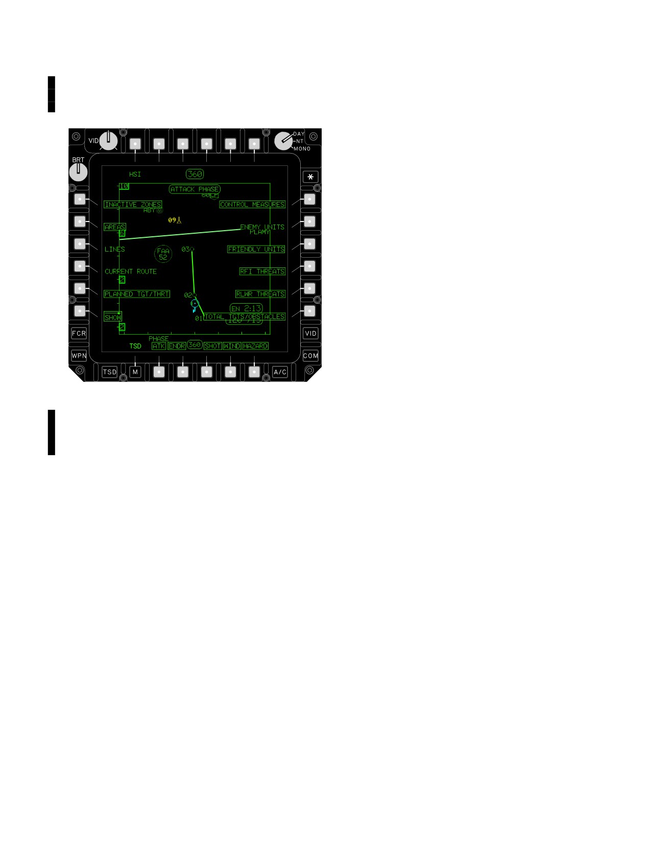
TM 1-1520-251-10
3.68.2 SHOW Page - Attack (ATK) PHASE. The ATK
• R6
TOTAL TARGETS/OBSTACLES
PHASE of the SHOW page (fig 3-72) provides information
button
pertaining to the battle area.
• B4
SHOT button
• B5
WIND button
• B6
HAZARD button
a. HSI Button. Selecting the HSI button displays
the magnetic compass rose on the TSD.
b. INACTIVE ZONES Button. Selecting the INAC-
TIVE ZONES button displays the inactive fire zones on
the TSD.
c. CURRENT ROUTE Button. Selecting the CUR-
RENT ROUTE button displays the current route and all of
its selected points, including direct-to navigation points on
the TSD.
d. TOTAL TGTS/OBSTACLES Button. Selecting
the TOTAL TGTS/OBSTACLES button displays the low
priority FCR targets or obstacles on the TSD.
e. WIND Button. Selecting the WIND button dis-
LBA3021
plays wind direction/velocity on the TSD.
Figure 3-72. SHOW Page - ATK PHASE
f. SHOT Button. Selecting the SHOT button dis-
plays the shot-at X’s on the TSD.
The ATK PHASE of the SHOW page (fig 3-72) contains
g. HAZARD Button. Selecting the HAZARD button
the following unique buttons:
displays all hazard symbols on the TSD
• T1
HSI button
h. ATTACK PHASE Status Window. The ATTACK
• L1
INACTIVE ZONES button
PHASE status window displays the status of the PHASE
• L4
CURRENT ROUTE button
button.
Use or disclosure of this information is subject to the restriction(s) on the title page of this document.
Change 2
3-89
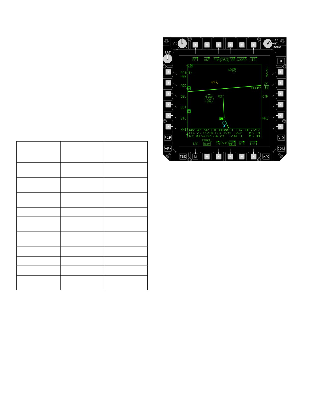
TM 1-1520-251-10
3.69 SUMMARY OF SYMBOL DISPLAY BY PHASE
The symbology and/or information on the TSD page de-
pends on the state of the PHASE selection as previously
described. The following lists the categories of symbology
displayed at any one time according to the selected
phase. Categories in italics are always displayed within
the respective phase, and have no selection available on
the page.
NAV PHASE
BOTH PHASES
ATK PHASE
CURRENT
LINES
CURRENT
ROUTE (With
ROUTE (With
Waypoints)
Waypoints)
LBA0421A
WAYPOINTS
PLANNED TGT/
TOTAL TGTS/
THRT
OBSTACLES
Figure 3-73. WPT Page
HAZARDS
CONTROL
SHOT
The WPT page contains the following unique buttons:
MEASURES
• L1
POINT button
OBSTACLES
FRIENDLY
UNITS
• L2
ADD button
• L3
DEL button
RFI THREATS
•
L4
EDT button
RLWR
• L5
STO button
THREATS
•
L6
XMIT button
HIGH
3.70.1 POINT Button. Selecting the review POINT but-
PRIORITY FCR
ton arms the KU for entry of the point type (W, H, or C) and
ENDR
the point number. The cursor can also be used to select
the point.
HSI
3.70.2 ADD Button. The WPT ADD button allows the
WIND
creation of a new waypoint, hazard, or control measure
INACTIVE
which is added to the coordinate data files. It displays only
ZONES
when there is an available point in either the waypoint/
hazard or control measure file. Selecting the WPT ADD
button calls up the IDENT button and the Point TYPE but-
tons. The system shall default to selecting the waypoint
3.70 WAYPOINT (WPT) PAGE
WP button if there is at least one slot available in the way-
point/hazard file.
a. Point TYPE Buttons. The point TYPE buttons
are displayed when the WPT ADD button is selected.
The WPT page, (fig 3-73) provides the ability to manage
These buttons are used to select the type of point to be
the waypoints/hazards and control measures files. The
added to the file. Selecting a point TYPE button sets the
WPT page defaults to reviewing the active destination
type of coordinate data according to the respective selec-
point. The crewmember can select any waypoint, hazard,
tion. When the waypoint, hazard, or control measure file is
or control measure for review.
full, the respective point TYPE buttons are not selectable.
Use or disclosure of this information is subject to the restriction(s) on the title page of this document.
3-90
TM 1-1520-251-10
(1) Waypoint (WP) Button. Selecting the WP
a. Delete YES Button. Selecting the Delete YES
button changes the type of the point to be added to way-
button will delete the currently selected waypoint, hazard,
point. The identifier defaults to WP.
or control measure that has been selected by the delete
POINT button.
(2) Hazard (HZ) Button. Selecting the HZ but-
b. Delete NO Button. Selecting the Delete NO but-
ton changes the type of the point to be added to hazard.
ton will cause the system to abort the delete process and
The identifier defaults to a Tower Under 1000 feet TU.
deselect the WPT DEL button.
3.70.4
Waypoint Edit (EDT) Button. Selecting the
(3) Control Measure (CM) Button. Selecting
WPT EDT button calls up the edit FREE button with the
the CM button changes the type of the point to be added
last valid coordinate data selected and the free text of the
to control measure. The identifier defaults to a Check
selected point.
Point CP.
a. Edit FREE Button. The edit FREE button will de-
b. Identifier (IDENT) Button. The IDENT button
fault to the current free text of the selected point.
displays only when the WPT ADD or EDT button is se-
If the defaulted text is not the desired free text, the crew-
lected. The IDENT button value changes to a default val-
member may input the new free text. Once the crew
ue depending on the TYPE button selected. If the de-
selects keyboard ENTER the button label will change to
faulted value is not the desired identifier, the crewmember
UTM LAT/LONG. The crewmember can either accept the
may input another identifier through the KU. Once the
default position of the selected point or enter a different
Keyboard ENTER button has been selected, the button
coordinate through the KU. An example of each is:
label will change to FREE TEXT. The crew can either en-
• 1) UTM: 11SGQ52184911
ter up to 3 characters or default to point type and number,
e.g. W03 for waypoint 03. When the crewmemeber se-
• 2) LAT/LONG: N742594W1205768
lects the Keyboard ENTER button again, the button label
When the crewmember selects the keyboard ENTER but-
will change to UTM LAT/LONG. The crew can either ac-
ton, the button label will change to ALTITUDE. The crew-
cept the default present position of the aircraft or enter a
member can either accept the default altitude of the se-
different coordinate through the KU. An example of each
lected point or enter a different altitude. After the altitude is
is:
edited, the system displays the selected point as modified
• 1) UTM: 11SGQ52184911
in the waypoint review status window and the WPT EDT
button is automatically deselected.
• 2) LAT/LONG: N742594W1205768
3.70.5 Waypoint Store (STO) Button. Selecting the
WPT STO button calls up the NOW button used to store a
Entry convention for LAT/LONG is one contiguous string
waypoint within the coordinate data files using the flyover
with no decimal points in degrees, minutes and hun-
store process. The waypoint review status window dis-
dredths of minutes. Latitude Northing degrees will contain
plays only the waypoint identifier, type, and altitude
two digits; Longitude Easting degrees will contain three
associated with the point file data to be added. The default
digits with leading zeros. 3) Point type and number : C95.
values used are as follows:
4) Pick a point off the map using the cursor (the cursor
coordinate will update in the review status window).]
• Point Type: W
When the crewmember selects the Keyboard ENTER but-
• Point Number: The next lowest number availa-
ton the button label will change to ALTITUDE. The crew-
ble
member can either accept the default aircraft Mean Sea
Level (MSL) altitude or enter a different altitude through
• Point Identifier: WP
the KU. After the altitude is edited, the system displays the
• Free Text: FLY
selected point as modified in the waypoint review status
• Altitude: Present position MSL terrain altitude if
window and the WPT ADD button is automatically dese-
the valid necessary information of ADS and Radar
lected.
Altimeter is available.
3.70.3 The Waypoint Delete (DEL) Button. Selecting
a. NOW Button. The NOW button commands the
the WPT DEL button calls up the delete POINT button
system to add a waypoint using the current aircraft posi-
with the last valid coordinate data selected and the DE-
tion and altitude. The free text will read FLY for waypoints
LETE YES/NO buttons.
stored using the flyover method.
Use or disclosure of this information is subject to the restriction(s) on the title page of this document.
3-91
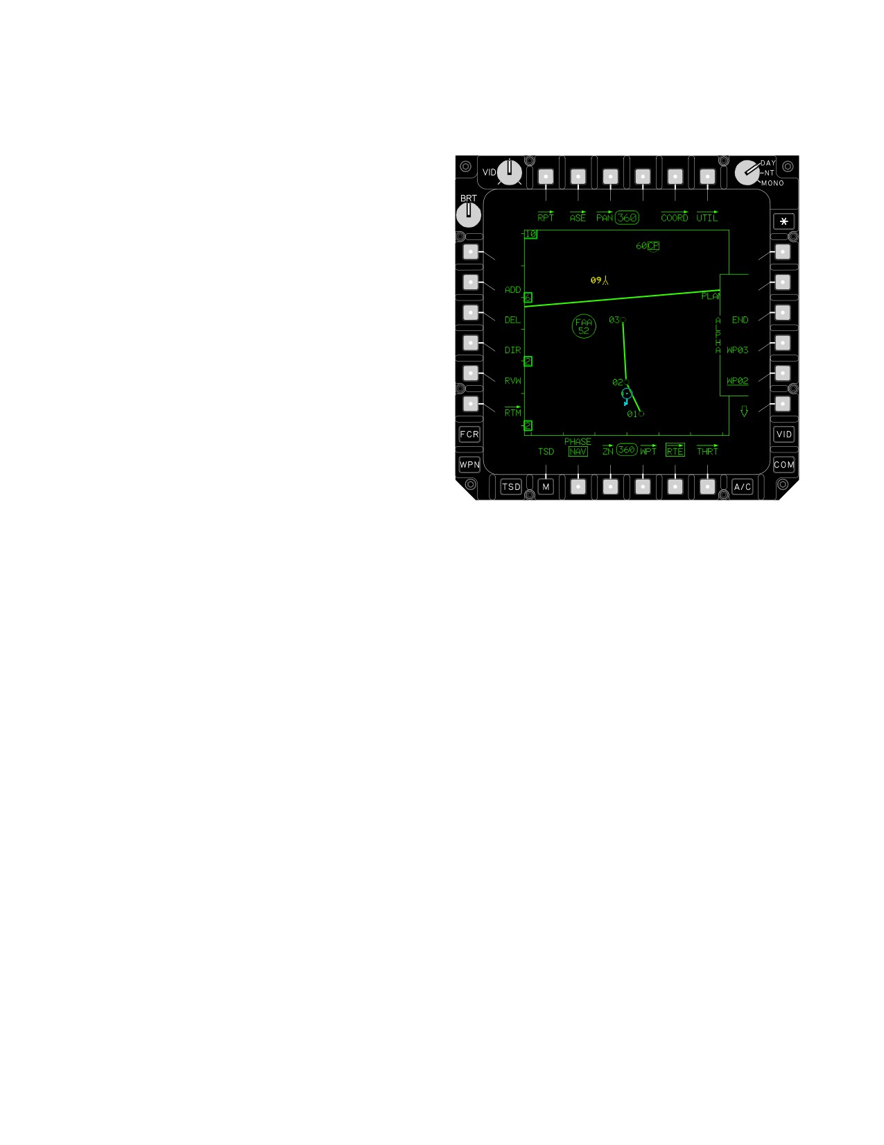
TM 1-1520-251-10
b. TADS LOS Store Procedure. An optional meth-
add or delete points in a route. It provides the ability to
od to store a waypoint using the WPT STO button is to
create direct to routes to selected points.
designate the point to be stored using the TADS laser. The
CPG must sight select TADS and arm the aircraft After se-
lecting the WPT STO button the CPG will point the TADS
laser to the correct location and lase for range and select
the STORE pushbutton on the ORT LHG. This will cause
the system to add a waypoint to the system using the off-
set from the TADS laser range to the aircraft position and
the aircraft altitude. TADS LOS can also store waypoints
using (Auto Range), (Default Range) or (Manual Range).
Waypoints can also be stored using HMD and (Auto
Range), (Default Range) or (Manual Range).
The free text in the WPT status window will reflect the
LOS used to store the target, TAD or HMD.
3.70.6
Waypoint XMIT Button. Selecting the WPT
XMIT button calls up the send POINT button with the last
valid coordinate data selected and the transmit SEND but-
ton used to send a waypoint, hazard, or control measure
over the IDM communication network.
3.70.7 Waypoint Review Status Window. The way-
LBA0872A
point review status window in the lower part of the map-
ping area provides coordinate data pertaining to a se-
Figure 3-74. RTE Page
lected point depending upon the moding of the WPT page.
The data fields displayed within the status window include
the following:
The RTE page also contains the following unique buttons:
• Point Type and Number
• L1
POINT button
• Point Identifier
• L2
ADD button
• L3
DEL button
• Free Text Identifier
• L4
DIR button
• Estimated Time Enroute (ETE)
•
L5
RVW button
• Estimated Time of Arrival (ETA)
• L6
RTM button
• Spheroid
• R1
Route Scroll Up button
• Datum
• R2 - R5 Route POINT buttons
• R6
Route Scroll Down button
• UTM Coordinates
3.71.1 POINT Button. Select the POINT button and
• Bearing
enter the point to be added using the KU or the cursor
• Distance to Go (Km)
control to select the point to be added from the map dis-
play. Next, select the point in the route window which the
• Latitude/Longitude Coordinates
selected point is to be inserted (in front of). The system
• Altitude
modifies the route to include the selected point.
• Distance to Go (NM)
3.71.2 ADD Button. Selecting the ADD button allows
the crew to add existing waypoints, hazards, and control
3.71 ROUTE (RTE) PAGE
measures to the current route. The system does not per-
mit adding a target or threat to the route. To add a point to
The RTE page (fig. 3-74) allows the crewmember to ac-
the route, first select the ADD button, and the system calls
cess current route information, select a new route, and
up the POINT button.
Use or disclosure of this information is subject to the restriction(s) on the title page of this document.
3-92
TM 1-1520-251-10
3.71.3 Delete (DEL) Button. Selecting the DEL button
3.71.8 Route POINT Buttons. The route POINT num-
allows the crew to delete an existing waypoint, hazard, or
ber buttons provide the ability to review, add, delete, or
control measure from the current route. To delete a point
perform a direct route to a point in the current route. The
from the route, first select the DEL button. Next, select the
point label which represents the active destination is un-
Route Point Number button which lists the point for dele-
derlined. The route number option buttons act as momen-
tion. The system modifies the route to exclude the se-
tary buttons when adding, deleting or performing a direct-
lected point.
to to a point in the current route.
NOTE
3.71.9 Route Window. The route window provides a
status window which displays the next four waypoints,
The Next Waypoint Status Window will re-
hazards, or control measures in the current route. The
flect the point selected as ”DIRECT TO”.
route name displays within the bracket along the left side
of the window.
3.71.4 Direct (DIR) Button. Selecting the DIR button
allows the crew to select an existing waypoint, hazard, or
3.71.10 RTE Review Status Window. The RTE review
control measure as the point to which a direct route will be
status window in the lower area of the map provides the
created.
ability to review coordinate point data for points in the cur-
rent route. This window displays only when the RVW but-
NOTE
ton is selected and a Route button is selected. The data
fields of the route review status window include the follow-
When either a direct-to inside the route or
ing:
outside the route is created, the route line
will go partial intensity, and the direct-to
• Point type and number
route line will be shown in full intensity.
• Point identifier
a. Direct To In The Route. To create a direct route
• Free text identifier
to a point, first select the DIR button and the system
makes the Route Point buttons available for selection.
• Estimated Time Enroute (ETE) based on position
Next, select the point in the route window at which the di-
of the aircraft in the route
rect-to route is to be created.
•
Estimated Time of Arrival (ETA) based on position
of the aircraft in the route
b. Direct To Outside The Route. To create a direct
route to a point, outside the route, first select the DIR but-
• Distance to go along the route (KM)
ton. The system calls up the POINT button. Select the
• Distance to go along the route (NM)
POINT button and enter the point to which a direct route
will be created using the KU, or use the cursor control to
select the point to which a direct route will be created from
the map display.
CAUTION
3.71.5
Route Review (RVW) Button. Selecting the
The Next Waypoint Status Window will
RVW button allows the crew to select a waypoint, hazard,
reflect the first point in the selected
or control measure for review using the route point but-
route. To enter route from other than the
tons displayed in the RTE review status window. Selecting
start point, perform a ”DIR TO” to the ap-
the RVW button causes the route point buttons to be ac-
propriate waypoint to ensure the Next
tive for selection. Selecting one of the route point buttons
Waypoint Status Window is valid.
causes the RTE review status window to be displayed.
3.72
ROUTE MENU (RTM) PAGE
3.71.6 Route Menu (RTM) Button. The RTM button al-
lows access to the Route Menu page.
The RTM page (fig 3-75) allows the crewmember to re-
view stored route information, select a route for naviga-
3.71.7 Route Scroll UP/DOWN Buttons. Selecting the
tion, or delete a stored route. Two pages display a total of
route scroll buttons causes the points within the route to
ten stored routes. The NEW route button defaults to se-
shift in order to display points along the route.
lected upon display of the page.
Use or disclosure of this information is subject to the restriction(s) on the title page of this document.
3-93
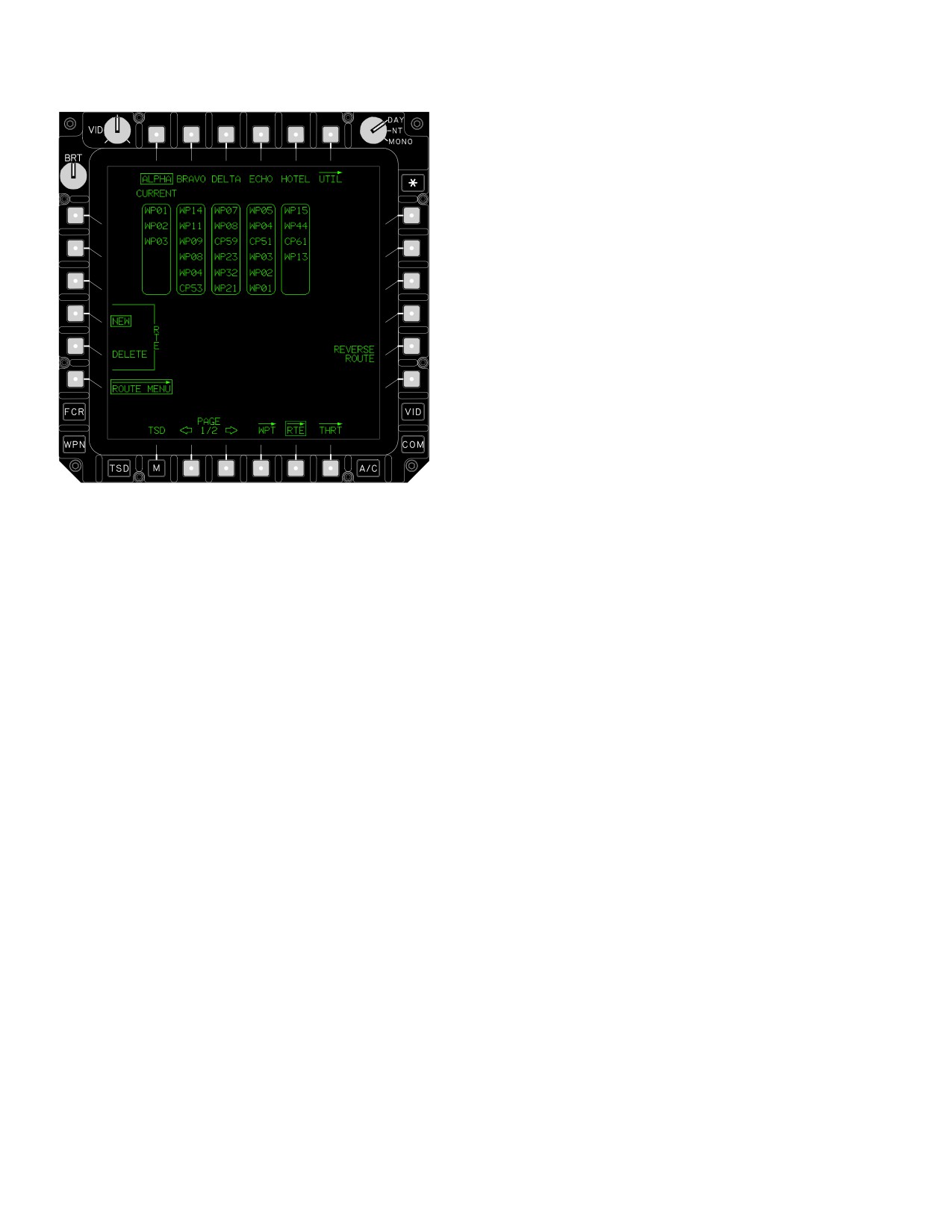
TM 1-1520-251-10
Once the RTE DELETE button is selected, selecting one
of the route name buttons calls up the delete route YES
and NO buttons.
a. RTE Delete YES Button. Selecting the delete
route YES button will cause the system to delete all the
points from the selected route. The coordinate data of the
points will remain in memory.
b. RTE Delete NO Button. Selecting the delete
route NO button will cause the system to abort the delete
route process.
3.72.4
REVERSE ROUTE Button. The REVERSE
ROUTE button allows the crewmember to reverse the
waypoint order in the current route. If the active point in
the current route is the first point, the new active point will
be set to the last point. If the active point is not the first, the
new active point will be set to the previous point. If a di-
rect - to point is the active point, the active point will not be
LBA0887A
changed.
Figure 3-75. ROUTE MENU (RTM) Page
3.72.5 Route Status Windows. A route window is dis-
played for each of the five routes presented on RTM page
1 or 2 to indicate the first 6 points within each route and
The RTM page contains the following unique buttons:
the route selected as the current route. A route window
• T1 - T5
Route name buttons
displays just below its associated route name button in the
upper area of the format. In addition, the CURRENT label
• L4
RTE NEW button
displays just above the route window which is selected as
• L5
RTE DELETE button
the current active route for navigation.
• R5
REVERSE ROUTE button
3.73 THREAT (THRT) PAGE
3.72.1 Route Name Buttons. The Route Name but-
tons provide the ability to select a particular route to be the
The THRT page (fig 3-76) provides the ability to review
current route for navigation or to be deleted from the route
selected target/threat information and add, delete, edit,
file. The CURRENT label is displayed just above the se-
store, or send target and threat data. Selecting the THRT
lected route window. Route name can only be entered
page button calls up the threat page in the review mode.
through the AMPS.
The selections made from the THRT page are identical to
the selections made on the WPT page with a few excep-
3.72.2 RTE NEW Button. Selecting the RTE NEW but-
tions. When adding a target/threat the crew must select a
ton allows the crewmember to designate a route as the
type of the point to be added, however, TG is the default.
new current route for navigation.
It will always be added as a target. When performing a tar-
get store the default value for the point type will be TG. In
3.72.3 RTE DELETE Button. The RTE DELETE but-
addition, whenever the KU is used and the point type is to
ton allows the crewmember to permanently delete a route.
be entered, a T will be used instead of the W, H or C.
Use or disclosure of this information is subject to the restriction(s) on the title page of this document.
3-94
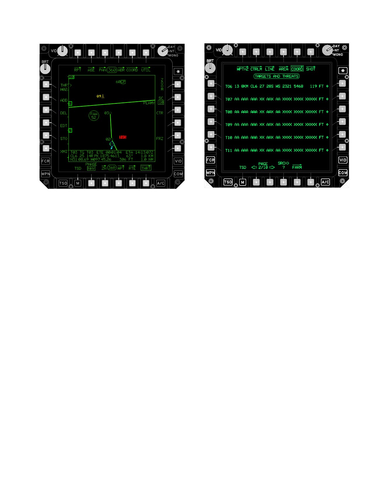
TM 1-1520-251-10
LBA1929A
LBA2546A
Figure 3-77. COORD Page
• T1
WPTHZ button
• T2
CTRLM button
Figure 3-76. THREAT (THRT) Page
•
T3
LINE button
• T4
AREA button
• T6
SHOT button
3.74 COORDINATE (COORD) PAGE
• L1 -L6
Acquisition Selection buttons
• R1 - R6 Point Expansion buttons
• B4
Search (SRCH) button
The target/threat COORD page (fig 3-77) provides access
to coordinate file data. The COORD page contains the
• B5
FARM button
complete coordinate data file of stored targets and
3.74.1
Waypoint/Hazard
(WPTHZ) Page But-
threats. The COORD page also provides the ability to se-
ton. Selection of the WPTHZ button will cause the way-
lect a target or threat as the acquisition option or to ex-
point/hazard page to be displayed.
pand the display of detailed target or threat information for
review. The system shall initialize to the first page unless
3.74.2
Control Measures
(CTRLM) Page But-
the current acquisition source (T##) is a target or threat.
ton. Selection of the CTRLM button will cause the con-
This file is capable of storing up to 50 targets or threats on
trol measures page to be displayed.
ten display pages of six points per page. If the crew at-
tempts to add or store more than 50 targets or threats, the
3.74.3 LINE Page Button. Selection of the LINE button
system overwrites the target or threat starting one location
will cause the LINE page to be displayed.
past the end of the target and threat safe set. The target
3.74.4 AREA Page Button. Selection of the AREA but-
and threat file has up to 25 locations protected from over-
ton will cause the AREA page to be displayed.
writing referred to as the safe set. The SP protects all tar-
gets, up to 25, that are loaded from the DTC. The crew
3.74.5 Shot-At (SHOT) Page Button. Selection of the
can edit these protected files, but they will not be overwrit-
SHOT button will cause the Shot-At page to be displayed.
ten. The SP will only use these protected locations for
storing if the target or threat that was initially loaded in that
3.74.6 Target/Threat Coordinate Acquisition Selec-
location has previously been deleted. See paragraph
tion Buttons. The COORD acquisition select buttons
3.62.6 for additional information regarding the addition of
rapidly select a target or threat from the file as an acquisi-
a new target (T51), the ATHS TARGET.
tion source.
Use or disclosure of this information is subject to the restriction(s) on the title page of this document.
3-95
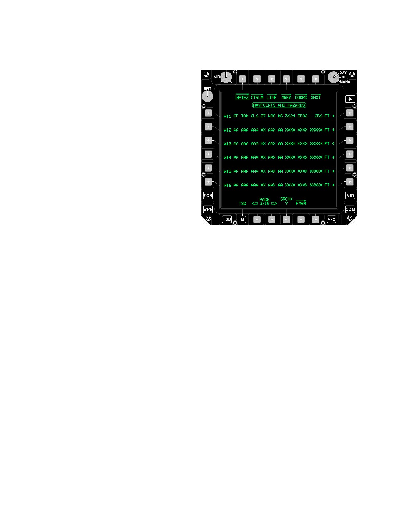
TM 1-1520-251-10
3.74.7
Target/Threat Coordinate Expansion But-
first page unless the current acquisition source (T##) is a
tons.
Selection of the COORD expansion buttons ex-
waypoint or hazard.
pands the single line of target or threat information into
three lines of information. The single line of target or threat
information contains the following:
• Target/Threat type and number
• Target/Threat identifier
• Free text identifier
• Spheroid
• Datum
• UTM coordinates
• MSL elevation
The expanded three lines of information contain the fol-
lowing additional information:
• Estimated Time Enroute (ETE)
• Estimated Time of Arrival (ETA)
• Bearing
LBA1930A
• Distance to go (Km)
Figure 3-78. WAYPOINTS and HAZARDS Page
• Latitude/Longitude coordinates
The selections made from the WPTHZ page are identical
• Distance to go (NM)
to the selections made on the COORD page except that
when selecting an acquisition select button, the acquisi-
When an expansion button is selected it will automatically
tion source will change to a waypoint or hazard instead of
deselect any other previously selected expansion button.
a target or threat.
3.74.8 Target/Threat Coordinate Search (SRCH) But-
3.76 CONTROL MEASURE (CTRLM) PAGE
ton. The target/threat coordinate SRCH button provides
the ability to rapidly search within the target/threat coordi-
The CTRLM page (fig 3-79) accesses the coordinate file
nate data file.
data of control measures. The CTRLM page allows for the
selection of a control measure as the acquisition option or
3.74.9 Fuel, Ammo, Rockets, and Missiles (FARM)
to expand the display of detailed control measure informa-
Button. Selecting the FARM button displays the FARM
tion for review. The control measure file is made up of 49
page. See paragraph 3.80.
points instead of 50 points like the target/threat and way-
point/hazard files. The system initializes to the first page
3.75 WAYPOINT/HAZARD (WPTHZ) PAGE
unless the current acquisition source (T##) is a control
measure. The selections made from the CTRLM page are
The WPTHZ page (fig 3-78) accesses the coordinate file
identical to the selections made on the COORD page ex-
data of waypoints and hazards. The WPTHZ page allows
cept for the following: When selecting acquisition select
for the selection of a waypoint or hazard as the acquisition
button, the acquisition source will change to a control
option or to expand the display of detailed waypoint or
measure instead of a target or threat. The SRCH button
hazard information for review. The system initializes to the
has a valid range of 51 to 99.
Use or disclosure of this information is subject to the restriction(s) on the title page of this document.
3-96
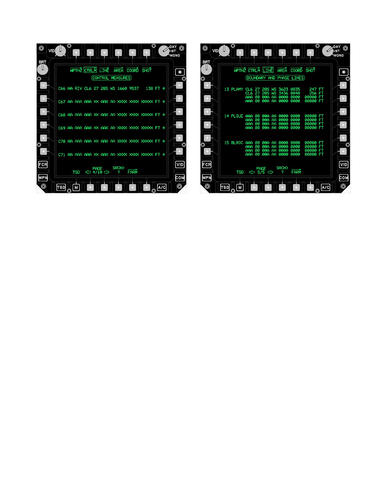
TM 1-1520-251-10
LBA5226
LBA5227
Figure 3-80. LINE Page
The list includes the following information:
Figure 3-79. CONTROL MEASURES Page
• Line file number
• Line identifier
• UTM coordinate for each point
• MSL altitude for each point
3.77 LINE PAGE
3.78 AREA PAGE
The AREA page shown in (fig 3-81) provides the ability to
The LINE page (fig 3-80) provides the ability to view the
view the coordinates associated with each of the 12 (max-
imum) areas stored in the navigation data base. The sys-
coordinates associated with each of the 15 (maximum)
tem initializes to the first page. The AREA page is identi-
boundary and phase lines stored in the navigation data
cal to the LINE page such that the page is for viewing only.
base. The system initializes to the first page. The LINE
One difference between the lines and areas is that each
data display area lists the data stored for each line in the
area must be made up of four points. The AREA data dis-
file. Each line may consist of between two and four points.
play area lists the data stored for each area in the file.
Use or disclosure of this information is subject to the restriction(s) on the title page of this document.
3-97
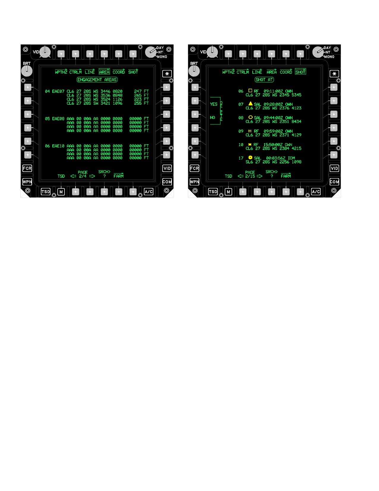
TM 1-1520-251-10
LBA5228
LBA5229
Figure 3-81. AREA Page
Figure 3-82. SHOT Page
The list includes all four points defining the area and in-
The SHOT page contains the following unique buttons:
cludes the following information:
• AREA file number
• L3
DEL button
• AREA identifier
3.79.1 Delete (DEL) Button. The DEL buttons allows
the crew to delete all shot-at location coordinate points
• Spheroid
received from other aircraft. Selecting the DEL button
• Datum
calls up the Delete Shot YES and Delete Shot NO buttons.
• UTM coordinate for each point
3.79.2 SHOT-AT Data Display Area. The SHOT-AT
• MSL altitude for each point
data display area lists the data stored for each shot-at in
the file. The display area includes the following informa-
3.79 SHOT PAGE
tion:
The SHOT page, shown in (fig 3-82) accesses the coordi-
• Shot-at file number
nate file data of shot-at locations stored in the navigation
• Target symbol
data base. This file is capable of storing up to 128 shot-at
locations on 26 display pages of 6 points per page. The
• Missile type
file is split into 2 parts. The first 16 locations are reserved
• Zulu Time of trigger pull
for targets shot-at by the ownship. The last 112 locations
are reserved for targets shot-at by other aircraft. If more
• OWN or IDM indication
that 16 targets are shot-at by the ownship, the system will
overwrite shot-at locations beginning with the first position
• Spheroid
in the file. If more than 112 shot-at locations are added to
• Datum
the file, the system will overwrite the shot-at locations be-
ginning with the 17th position in the file.
• UTM coordinate of Shot-at (para 3.62.16)
Use or disclosure of this information is subject to the restriction(s) on the title page of this document.
3-98
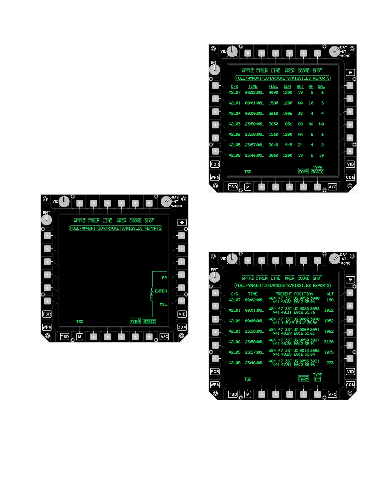
TM 1-1520-251-10
3.80 FUEL, AMMO, ROCKETS, AND MISSILES
(FARM) PAGE
The FARM page (fig 3-83) allows the crew to quickly re-
view FARM reports. Selecting the FARM button will dis-
play data from the last seven received FARM reports.
However, if a FARM report is received and the call sign
matches a FARM report currently in the system, the
FARM report will be overwritten. If a FARM report is re-
ceived and the call sign does not match an existing FARM
report it will be written to the next available location. If a
location is not available, the oldest FARM report will be
overwritten.
The TYPE button allows the crew to determine what type
of FARM report data is displayed PP, EXPEN, MSL or BA-
SIC. The reports are sorted from the newest to oldest
based on date/time (then by call sign).
LBA5007
Figure 3-84. BASIC FARM Data
b. PP Button (R4). Displays present position and
altitude information (fig 3-85) .
LBA5006
Figure 3-83. FARM Page
NOTE
If data is invalid or no launchers are present,
LBA5008
“NA” will be displayed in the appropriate col-
umn on the page.
Figure 3-85. PP FARM Data
a. BASIC Button. Displays basic FARM data (fig
3-84). The SAL column on this page displays the sum of
c. EXPEN Button. Displays all ASE Expendables
SAL1 and SAL2 missiles.
(fig 3-86).
Use or disclosure of this information is subject to the restriction(s) on the title page of this document.
3-99
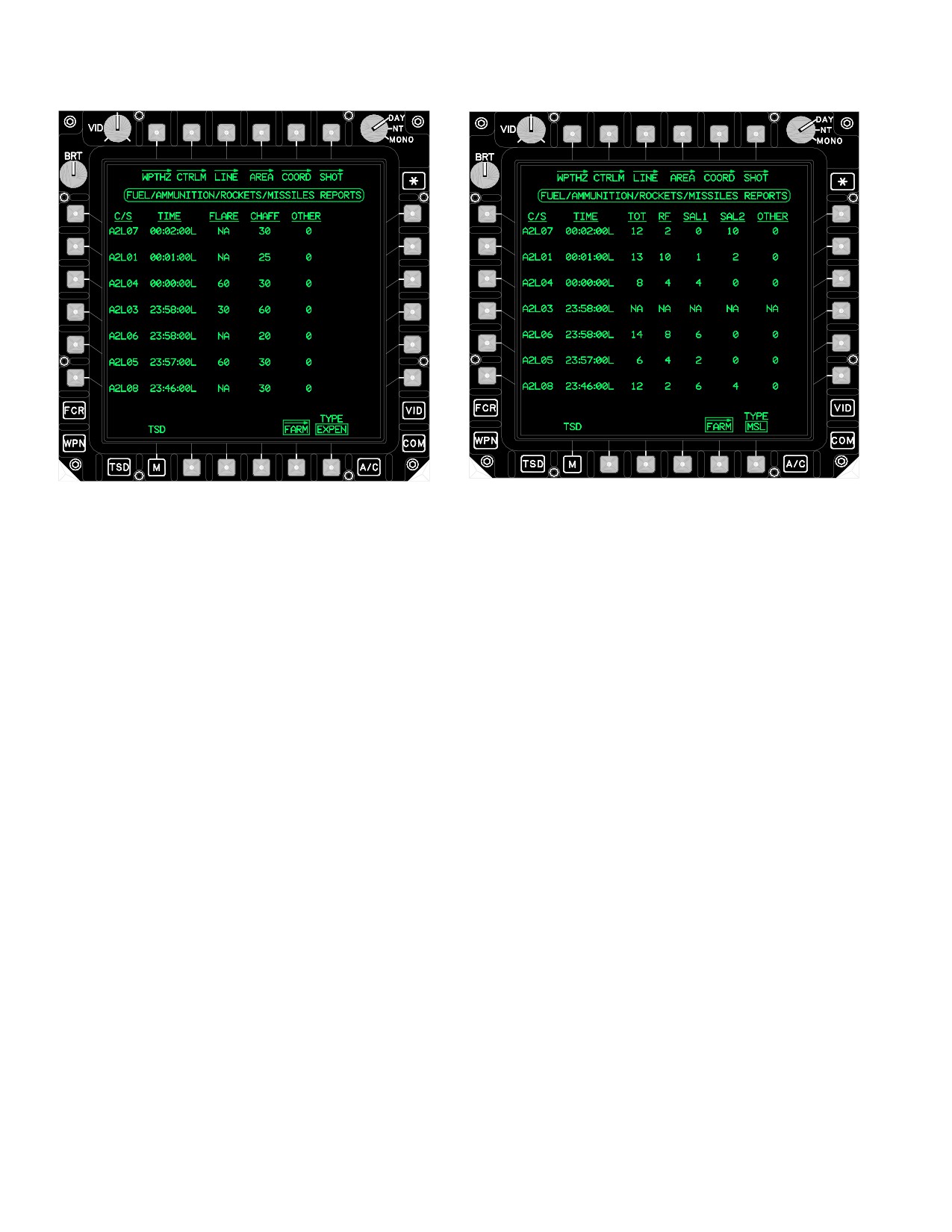
TM 1-1520-251-10
LBA5009
LBA5010
Figure 3-87. MSL FARM Data
Figure 3-86. EXPEN FARM Data
3.81 ZONE (ZN) PAGE
d. MSL Button. Displays specific Hellfire missile
The ZN page ( fig 3-88, or fig 3-89) may be displayed in
counts (fig 3-87). “Other” is the difference between the to-
the NAV or ATTACK phases. Selecting the ZN page will
tal missile count and sum of the RF, SAL1, and SAL2
freeze the TSD. The ZN page provides the ability to
counts.
construct and assign priority fire and no fire zones for the
battle management mission segment. A maximum of 8
priority fire zones and 8 no fire zones can be displayed on
the TSD. A maximum of 1 priority fire zone and up to 8 no
fire zones may be active at any time. Active PFZ and
NFZ’s will marquee to aid the crew in determining which of
the zones are active. The active priority fire and no fire
zones affect the prioritization on the next scan after the
zone has been created, received, or reassigned. FCR tar-
gets detected within an active priority fire zone out-priori-
tize the FCR targets which fall outside the zone. FCR tar-
gets detected within the active no fire zones are not
prioritized. Active PF and NF zones will marquee on the
TSD and FCR pages.
Use or disclosure of this information is subject to the restriction(s) on the title page of this document.
3-100
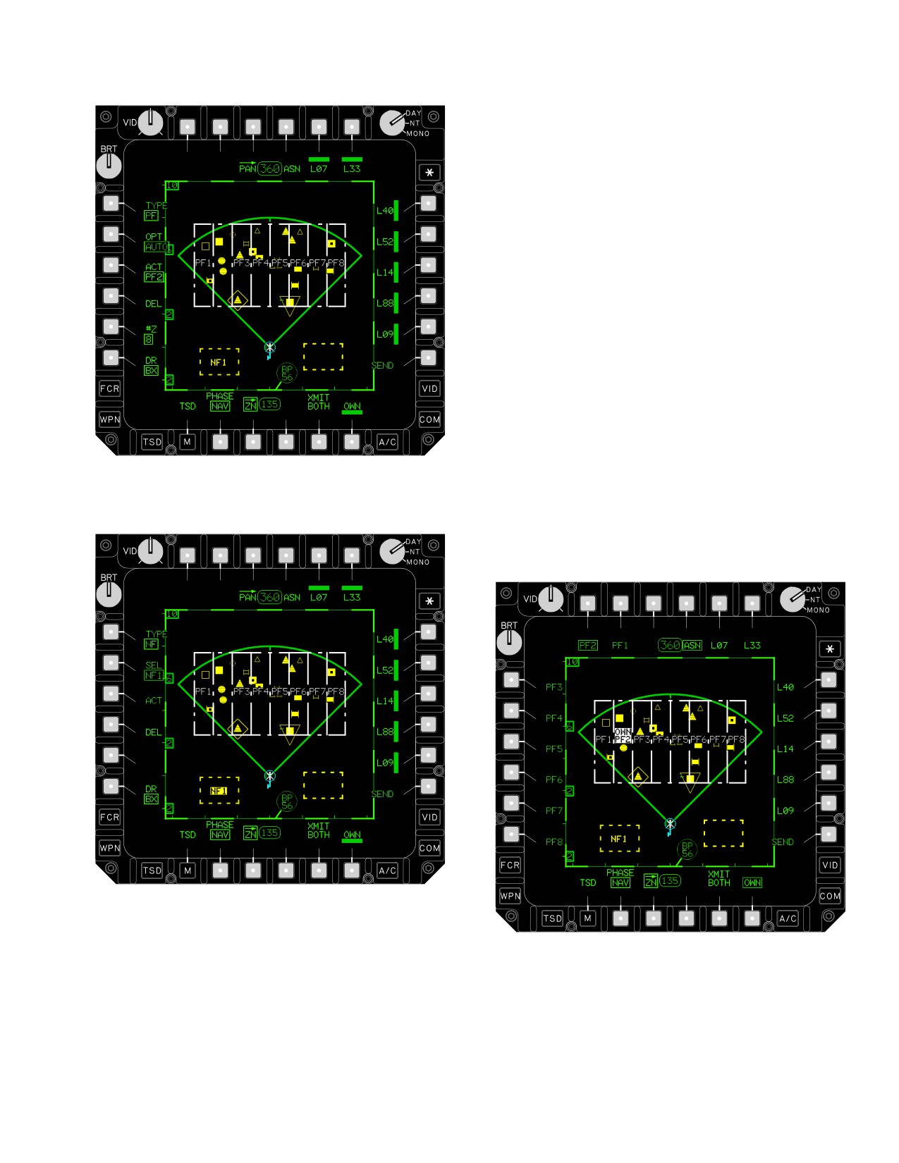
TM 1-1520-251-10
• T1
ACTIVE Button
• T4
ASN Button
• T5/6
Subscriber Buttons
• L1
TYPE Button
• L2
OPT Button
• L3
ACT Button
• L4
DEL Button
• L5
#Z Button
• L6
DR Button
• R1 - R5 Subscriber Buttons
• R6
SEND Button
• B2
CLR Button
• B5
XMIT BOTH Button
• B6
OWN Button
3.81.1 Assign (ASN) Button. Selecting the ASN but-
LBA3022
ton commands the system to display the Priority Fire Zone
Identifier buttons and make the Subscriber Identifier and
Figure
3-88.
ZN (Zone) Page, Type PF
OWN buttons available for selection, (fig 3-90). The ASN
button is displayed whenever priority fire zones are pres-
ent in the system or all the points for the zones being
created have been entered.
LBA3047
Figure 3-89. ZN (Zone) Page, Type NF
LBA5229
The ZN page contains the following buttons:
Figure 3-90. Assign (ASN) Button Selected
Use or disclosure of this information is subject to the restriction(s) on the title page of this document.
3-101
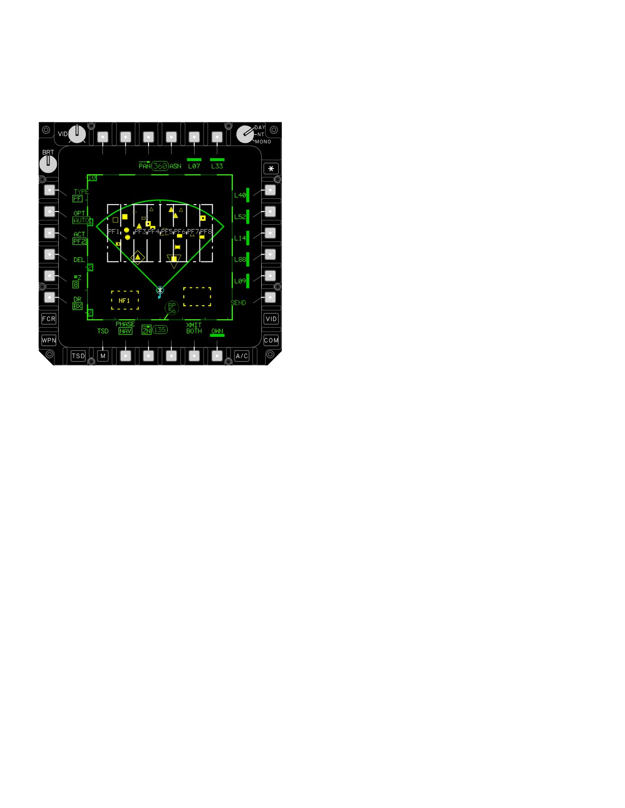
TM 1-1520-251-10
3.81.2 TYPE Button. The TYPE button allows the crew
3.81.5 Manual (MAN) Button. Selection of the MAN
to toggle between Priority Fire (PF) and No Fire (NF) zone
button enables the cursor to select points for each zone
controls (fig 3-91).
that will be created based on the current setting of the #Z
button. When the crew has selected the first point the CLR
button will be displayed. When the crew has selected the
last point of the last priority fire zone, the ASN and SEND
buttons will be displayed.
3.81.6 Number (#Z) Button. Selecting the #Z
(1 - 8) button allows the crew to select the number of zones
to be created. The number of the zones to be created de-
faults to the number of team members that are also zone
designated plus one for the ownship.
3.81.7 Draw (DR) Button. Selecting the MAN or AUTO
button calls up the DR button, which toggles between BX
(box) and LN (line) modes of the cursor operation. The
box mode allows the crew to select the lower left and up-
per right corners of a box for PF zone construction. The
LN mode allows the operator a quadrilateral polygon for a
PF zone. Using the LN method to draw PFZ, the zones
will be oriented parallel to the first line drawn.
LBA3022
3.81.8 Target Reference Point (TRP) Button. Selec-
tion of the TRP button removes all of the existing priority
Figure 3-91. ZN (Zone) Page, Type PF
fire zones from the MPD on which the TRP button is se-
lected. The crew selects the TRP button to create priority
fire zones using the target reference point method. Selec-
3.81.3 Option (OPT) Button. The OPT button is dis-
tion of the TRP button enables the cursor to select a point
played when the TYPE is PF, and allows the crew to select
on the map as the center of the priority fire zones to
the AUTO, MAN or TRP drawing method. AUTO is the de-
create. The size of the zones is based on the setting of the
fault.
kilometer K button. When the crew has selected the refer-
ence point, the ASN, CLR and SEND buttons will be dis-
3.81.4
Automatic (AUTO) Button. Selection of the
played.
AUTO button enables the cursor control to select four
points which connect to form a quadrilateral polygon
which encompasses the FCR targets. Selecting the fourth
a. Kilometer (KM) Button. The KM (kilometer) but-
corner of the polygon divides the polygon into a number of
ton displays when the TRP button is selected. Selecting
priority fire zones 1 - 8, as determined by the current value
the KM (kilometer) button allows the crew to select the
of #Z button. When the crew has selected the first point
size (1 - 3 km) of the TRP priority fire zones. The zone size
the CLR button will be displayed. When the crew has se-
is measured in terms of the length of one side of the
lected the last point, the ASN and SEND buttons will be
square box for each of the four zones. The default size is
displayed.
2 km.
Use or disclosure of this information is subject to the restriction(s) on the title page of this document.
3-102
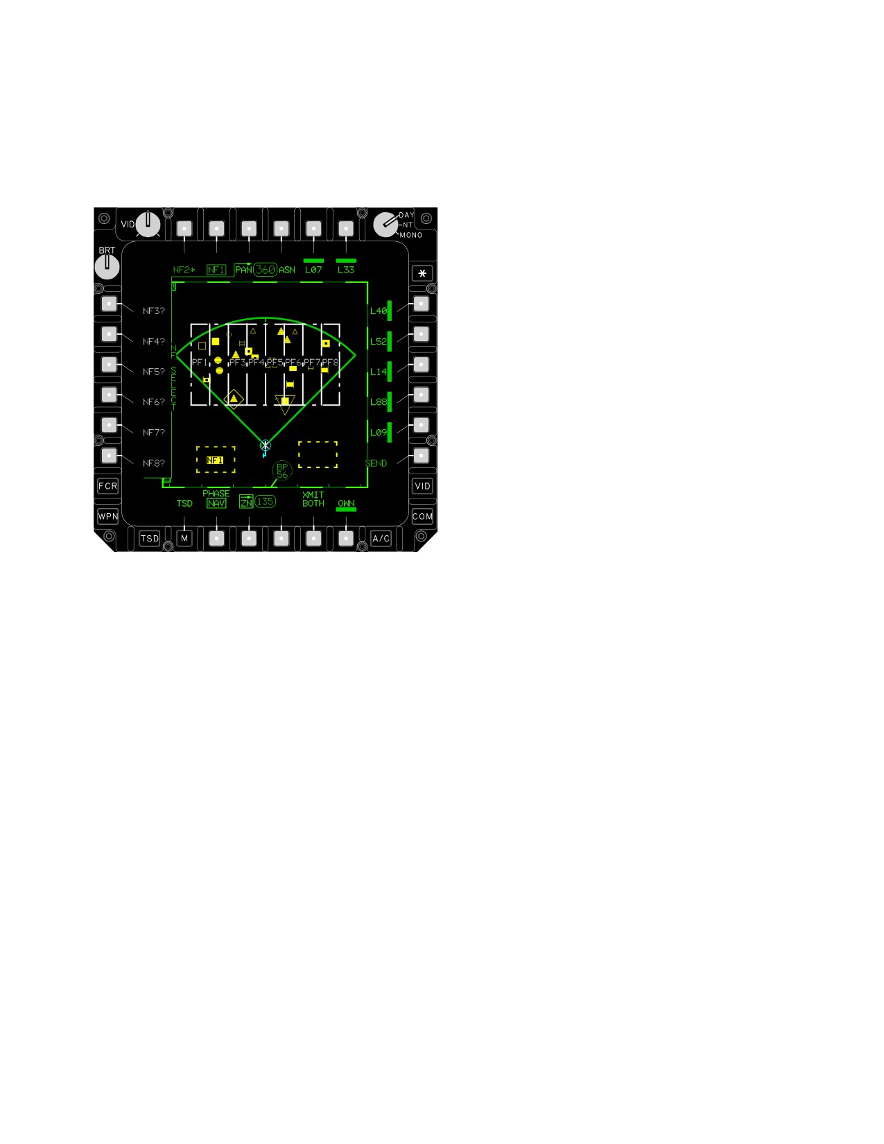
TM 1-1520-251-10
3.81.9 SELECT (SEL) Button. When the TYPE is NF,
NOTE
the SEL button allows the crew to select the NF zone to
• Instead of selecting the ACT or ACCEPT
modify (fig 3-92). Each active NFZ is indicated by a left
buttons, the crew may begin drawing the
pointing arrow. Empty zones (undrawn) are WHITE with a
next no fire zone and the previously
question mark next to the number.
drawn zone will automatically be ac-
cepted.
• The DP will keep track of all the active no
fire zones and the single active no fire
zone when the ACTIVE button is set to
MULTI for backwards compatability. This
will allow the receiving DP to use the ap-
propriate data, either multiple active no
fire zones or a single active no fire zone
based on the receiving aircrafts current
capability.
• Both the DP and the FCR will automati-
cally configure to the capability of the
other. This will allow an FCR with single
active no fire zone capability to be
installed with a DP with multiple active no
fire zone capability or vice - versa with no
impacts other than the functional differ-
ences between multiple and single active
no fire zone.
3.81.10 Active (ACT) Button. The ACT button allows
LBA3049
the selection of a new active priority fire zone or new ac-
tive no fire zone. The system displays the ACT button only
Figure
3-92.
NF SEL Button Selected
when priority fire zones are loaded into the system. or
when no fire zones are loaded into the system or are fin-
ished being drawn. When the ACTIVE button is set to
MULTI, each no fire zone can be individually activated or
deactivated using the ACT button. When a no fire zone is
being deactivated and it is the current single active no fire
zone, the first no fire zone that is found to be active start-
ing from NFZ1 will be selected as the single active no fire
zone for the IDM transmission.
3.81.11 Accept (ACCEPT) Button. The ACCEPT but-
ton allows the crew to accept a NFZ permanently if all the
points for the new NFZ have been entered.
3.81.12 DELETE (DEL) Button. The DEL button al-
lows the crew to delete all Priority Fire zones or each No
Fire zone indvidually. Crew has YES/NO option.
Use or disclosure of this information is subject to the restriction(s) on the title page of this document.
3-103
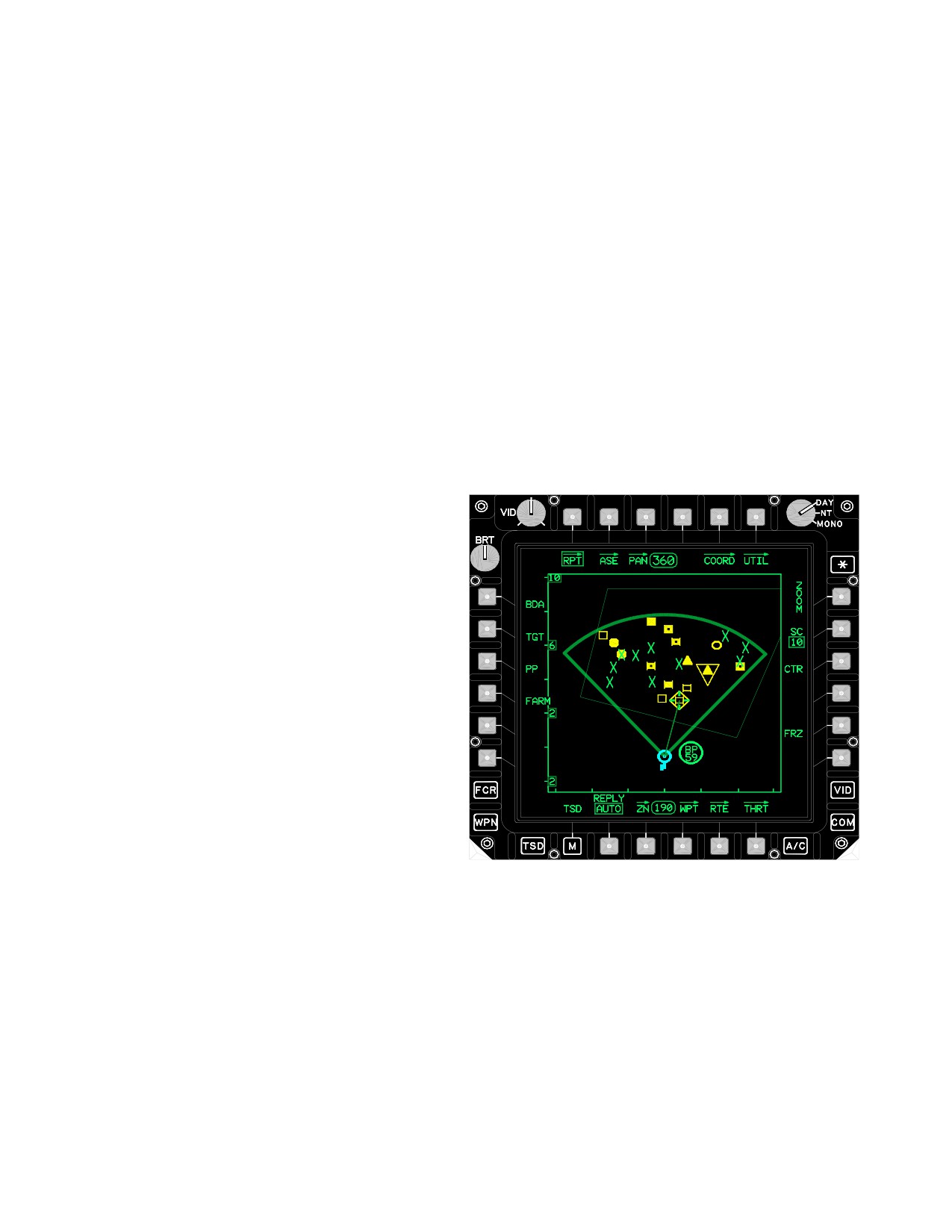
TM 1-1520-251-10
NOTE
3.81.19 Priority Fire Zones. A maximum of 8 priority
fire zones can be created/displayed on TSD. Only the ac-
Although the IDM messages will support
tive priority fire zone is displayed full intensity in WHITE.
sending data between differently configured
The inactive priority fire zones are displayed partial inten-
aircraft (i.e., some single active no fire zone
sity. The label for the active zone will be removed to allow
and some multiple active no fire zones) it is
the crew to easily identify the highest priority targets. The
advised that aircraft communicating be set
Active priority fire zone will be displayed in both GTM and
to the same active mode (if possible) to
ATM mode on the FCR Page.
avoid data being ignored due to different
modes of operation.
3.81.20 No Fire Zones. Eight no fire zones can be
created/displayed on TSD. No fire zones are displayed in
3.81.13 ACTIVE (ACTIVE) Button. When the TYPE is
full intensity in YELLOW. The active no fire zones will mar-
NF, the ACTIVE button allows the crew to switch between
quee on the TSD and FCR pages.
MULTI(ple) and SINGLE mode. When in MULTI active
mode, more than one no fire zone can be active at the
3.82 REPORT (RPT) PAGE
same time. When in SINGLE active mode, only one no fire
zone can be active at one time. If another no fire zone is
The RPT page (fig 3-93) provides the ability to send re-
active at the time a no fire zone is activated, it will auto-
ports using the IDM to network zone members, or to query
matically be deactivated. When the FCR is powered on,
those members for the indicated report. The RPT page
the ACTIVE button will be barriered and the DP will auto-
contains the following buttons:
matically mode to either MULTI or SINGLE based on the
capability of the FCR.
3.81.14 Subscriber Identifier Buttons. To assign indi-
vidual priority fire zones to each subscriber, the crew will
select the subscriber buttons in the desired sequence. In
turn, the system assigns PF1 to the first subscriber se-
lected, PF2 to the second subscriber selected, and so
forth, until all assignments are completed. The crew may
also deselect the subscriber identifier buttons to remove
the subscriber from the selected priority fire zone.
3.81.15 SEND Button Selecting the SEND button trans-
mits the priority fire zones to the selected zone members
on the IDM net. The SEND button will be displayed when
the last point of the priority fire zones or no fire zone,being
created has been entered. The XMIT BOTH button will
determine if both the PF and NF zones are transmitted or
only the current type of zone determined by the TYPE but-
ton are transmitted.
LBA0949B
3.81.16 Clear (CLR) Button. The CLR button clears
the last cursor entry for the polygon in progress. Subse-
Figure 3-93.
RPT Page
quent selections will remove the next to last cursor entry
and so on.
• T1
RPT button
3.81.17
XMIT BOTH Button. Selecting the XMIT
• L1
BDA button
BOTH button allows the crew to select/deselect sending
• L2
TGT button
both PF and NF zones when SEND is selected.
• L3
PP button
3.81.18 OWN Button. The crew selects the OWN but-
• L4
FARM button
ton to assign the selected priority fire zone to the ownship.
• T5 - T - 6, R1 - R5 Subscriber buttons
The system displays the word OWN in the center of the
priority fire zone assigned to the ownship.
• B2
REPLY/MSG button
Use or disclosure of this information is subject to the restriction(s) on the title page of this document.
3-104
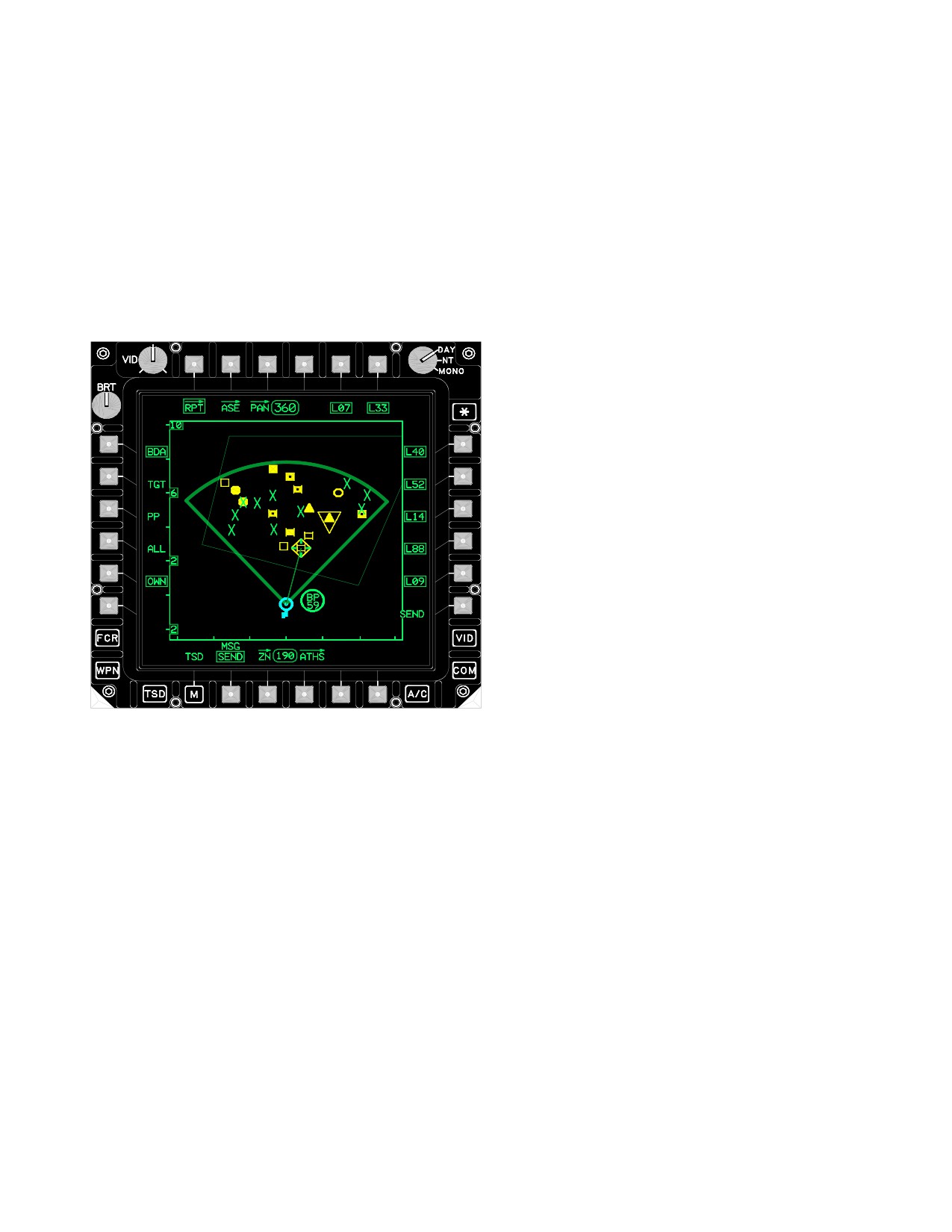
TM 1-1520-251-10
3.82.1 Battle Damage Assessment Report (BDA) But-
individual FCR target that the system will transmit out
ton. Selecting the BDA button calls up the ALL and
when the crew selects the SEND button.
OWN buttons. The OWN button is default selected.
3.82.3 Present Position (PP) Report Button. Select-
a. ALL BDA Button. Selecting the ALL button
ing the PP button commands the system to transmit out
instructs the system to transmit all of the BDA reports
the aircraft present position when the crew selects the
when the crew selects the SEND button.
SEND button.
b. OWN BDA Button. Selecting the OWN button
3.82.4
Fuel, Ammo, Rockets, and Missles (FARM)
instructs the system to transmit BDA reports for the own-
Button. Selecting the FARM button commands the sys-
ship when the crew selects the SEND button.
tem to display the FARM REPORT page.
NOTE
• If a system is turned off the message will
indicate its information is not available.
• If the aircraft is in simulation mode, the
simulated inventory will be sent.
• If the aircraft is configured for TESS and
has detected any live ordinance the gun
quantity present, rocket launcher pres-
ent, and HELLFIRE launcher present will
indicate not present in the message. The
message will indicate the gun, rocket,
and HELLFIRE quantities are not avail-
able.
• If equipment failure occurs (or hang fires)
those quantities will not be included in the
message.
a. The following data will be transmitted to all selected
LBA5011
subscribers when the crew selects the SEND button. No
addtional operator input is required.
Figure 3-94. Page Layout When BDA Is Selected
• Call Sign (5 characters)
• Date (month, day, and year)
3.82.2 Report FCR Targets (TGT) Button. Selecting
the TGT button calls up the ALL and PRI (Priority) but-
• Present Position (Lat/Long)
tons, and enables the cursor to select individual FCR tar-
• Elevation (feet)
get(s).
• Fuel Quantity (Lbs)
a. ALL FCR Targets Button. Selecting the ALL
• Gun rounds present and quantity
button instructs the system to transmit out all of the FCR
targets (high and low priority) when the crew selects the
• Rockets (launcher present and quantity)
SEND button.
• Hellfire missles (quantity of SAL 1, SAL 2, and RF)
b. Priority (PRI) FCR Targets Button. Selecting
• Quantity of all ASE Expendables
the PRI button instructs the system to transmit out all of
the high-priority FCR targets when the crew selects the
3.82.5 Subscriber Buttons. Are used to select sub-
SEND button.
scriber to receive transmission. The default for the TGT,
PP and FARM messages is all of the subscribers selec-
c. Selecting Individual FCR Targets. If neither the
ted. The default for the BDA message is none of the sub-
ALL nor the PRI button is selected, the crew can select an
scribers selected.
Use or disclosure of this information is subject to the restriction(s) on the title page of this document.
3-105
TM 1-1520-251-10
3.83 INITIALIZATION
3.84 NORMAL OPERATIONS
The following paragraphs describe procedural steps re-
The Navigation subsystem initializes automatically upon
quired for interface with the navigation subsystem via the
aircraft power application. The present position will be au-
TSD, and the systems response to crewmembers input.
tomatically loaded by the SP. If a present position does not
exist, the crew can enter in the present position using the
3.84.1 Add a Waypoint, Hazard, Control Measure.
position update procedure (para 3.83.1). Should power be
interrupted, the system stores the last known aircraft posi-
1.
TSD page - Select.
tion. Upon application of power, the system initiates an
alignment as follows:
2.
WPT page - Select.
• Starts EGI alignment
3.
ADD button - Select.
• Reads the last stored present position
4.
TYPE button - Select Waypoint (WP), Hazard
• Sets the Doppler Radar to ON
(HZ), or Control Measure (CM).
• Sets the map scale to 1:250K
5.
IDENT button - Enter Point identification on KU
• Reads all stored routes from memory and the
or accept default.
DTC.
6.
Free Text - Enter.
• Reads all waypoint, hazard, control measure,
target, threat, line and area data
7.
UTM or LAT/LONG coordinates - Enter.
• Sets the map and ownship symbol to the de-cen-
8.
Altitude - Enter or accept default.
tered position
• Sets TSD Map Frozen Cue
9.
ADD button - Select.
10.
POINT button - Select.
3.83.1 Perform a Fly-over or TADS LOS Position Up-
date.
a. Enter point type and number on the KU.
1.
TSD page - Select.
b. Select the point in the route window which
the added point is inserted in front of.
2.
PSN button - Select.
3.84.2 Add a Target or Threat.
3.
POSITION button - Select.
1. TSD page - Select.
a. Enter new position in either UTM or LAT/
2. THRT page - Select.
LONG coordinates using the KU.
3. ADD button - Select.
b. Fly over the new position.
4. IDENT button - Enter Point identification on KU
or accept default.
4.
UPT button - Select.
5. Free Text - Enter.
or
6. UTM or LAT/LONG coordinates - Enter.
RHG Sight Select switch - TADS.
7. Altitude - Enter or accept default.
5.
RHG LRFD trigger - Press.
3.84.3 Store a Waypoint.
6.
LHG STORE/UPDT switch - UPDT.
1. WPT page - Select.
Use or disclosure of this information is subject to the restriction(s) on the title page of this document.
3-106
Change 3
TM 1-1520-251-10
2. STO button - Select. Fly to point location.
a. TADS: Laser, Auto, Manual, or Default.
3. NOW button - Select.
b. HMD: Auto, Manual, or Default.
3.84.4 Add Existing Points to the Current Route.
4. Store button - Press.
1.
TSD page - Select.
3.84.6 Create Priority Fire Zones.
2.
RTE page - Select.
1.
TSD page - Select.
3.
ADD button - Select.
2.
ZN page - Select.
a. Cursor Method:
3.
Select AUTO Button for AUTO method of Prior-
ity Fire Zone creation, accept, or modify the #Z
(1) Select point using cursor.
button.
(2) Select the point in the route window
which the added point is inserted in front
a. Accept default Draw (DR) Box (BX) method
of.
or select DR Line (LN) button.
or
b. Select the corners of the Priority Fire Zone
using the cursor and enter function.
b. KU Method:
c. ASN button - Select.
(1) Enter point type, identification and num-
ber.
d. Select the desired subscriber button(s) to
assign the number of zones selected above.
(2) Select the point in the route window
which the added point is inserted in front
or
of.
Select MAN zoning button and accept or modify
3.84.5 Store a Target or Threat.
the #Z button.
1. TSD page - Select.
e. Accept default Draw (DR) Box (BX) method
or select DR Line (LN) button.
2. THRT page - Select.
f. Draw one to six priority fire zones using the
3. STO button - Select.
cursor and enter function in the box or line
mode. The number of zones to draw is
a. Option 1: Fly-over
based on the #Z button.
1. Fly to target or threat location.
g. ASN button - Select
2. NOW button - Select.
h. Select the desired subscriber description
button(s) to assign that PF zone as the ac-
b. Option 2: TADS/HMD LOS Method.
tive (full intensity) PF zone in the subscriber
aircraft.
1. Sight Select (CPG) - TADS or HMD.
2. Place selected sight on target.
or
3. Provide desired Range source:
TRP zoning button - Select.
Use or disclosure of this information is subject to the restriction(s) on the title page of this document.
Change 3
3-107
TM 1-1520-251-10
4. KM button - Accept or modify.
11. SEND button - Select.
a. Select desired point on the map display us-
3.84.8 Request BDA Reports or PP Reports.
ing the cursor and enter function.
1. TSD page - Select.
b. ASN button - Select
2. RPT page - Select.
c. Select subscriber description button(s) to
assign that PF zone as the active (full inten-
3. BDA - Select.
sity) PF zone in the subscriber aircraft.
4. MSG button - RQST.
3.84.7
Send BDA Reports (ALL or OWN), or TGT
Reports (Selective, ALL, PRI) or PP Reports.
5. Subscriber - Select as appropriate.
1. TSD page - Select.
6. SEND button - Select.
2. RPT page - Select.
or
3. BDA - Select.
PP - Select.
4. Either ALL or OWN - Select.
7. MSG button - RQST.
5. Subscriber - Select as appropriate.
8. Subscriber - Deselect as appropriate.
6. SEND button - Select.
9. SEND button - Select.
or
3.84.9 Add a New NF Zone.
TGT - Select.
1. TSD page - Select.
7. Select ALL or PRI or use cursor.
2. ZN page - Select.
8. Subscriber - Select as appropriate.
3. NF button - Select.
9. SEND button - Select.
4. DR button - Select LN or BX.
or
a. Select four corners of a quadrilateral poly-
gon (or two corners of the box rectangle) us-
PP - Select.
ing the cursor.
10. Subscriber - Select as appropriate.
5. OWN or SEND - Select.
Use or disclosure of this information is subject to the restriction(s) on the title page of this document.
3-108
TM 1-1520-251-10
CHAPTER 3A
BLK 2
AVIONICS
Section I.
GENERAL
3A.1 DESCRIPTION
degrees from the nose. Reception is
achieved up to a range of 22 NM except
Avionics equipment includes communication equipment
with frequencies above 145 MHz where
and navigation equipment. This chapter describes each
the direction degradation is severe.
major item with respective locations on the airframe and
antenna locations.
• The UHF-AM (ARC-164) radio provides
the second best overall performance. Two
3A.2 AVIONICS EQUIPMENT CONFIGURATION
line-of-sight blockages occur with the UHF
radio that completely block reception and
Communication/Navigation equipment configurations are
transmission due to pylon-mounted weap-
shown in Table 3A-1. Communication/Navigation antenna
ons. These blockages are in 25-degree di-
locations are shown in Figure 3A-1.
rectional arcs, from 012 to 037 degrees and
3A.3 AVIONICS POWER SUPPLY
from 323 to 348 degrees from the nose. A
slight range and audibility degradation oc-
curs around the tail directions from 120 to
CAUTION
240 degrees from the nose. Although trans-
missions are clear, the maximum reception
Uncommanded FM transmissions may occur
range for UHF is approximately 30 NM be-
during IDM IBIT, FALLBACK, when the CIU
low 300 MHz and approximately 35 NM
circuit breaker is open, or during CIU power-
above 300 MHz. Communications in com-
up. CIU power-up occurs during aircraft pow-
bat operations and with ATC should take
er-up and upon CIU circuit breaker reset.
these factors into consideration.
Power to operate all of the avionics communication equip-
• The FM-1 radio transmits clearly and pro-
ment is provided by the emergency dc bus. This allows back-
vides the third best overall performance. A
up battery power to be used in case of an aircraft electrical
slight range and audibility degradation oc-
failure. External power may also be applied. See Chapter 2,
curs at the low and high band of frequen-
Section XI for more information on electrical power supply.
cies in directions from 120 to 210 degrees
NOTE
from the nose. Reception is achieved up to
a maximum range of 29 NM for plain and
• Testing of the aircraft has shown that
22 NM for cipher text mode. The exception
there may be significant self - generated
is near 40 and 80 MHz where reception is
interference [HF missile launchers, Dop-
achieved to a maximum range of 23 and
pler Navigation System (DNS) antennae,
16.5 NM respectively. Non-line-of-sight re-
MPDs, etc.] and local conditions (radio,
ception is expected to be nonexistent.
television stations, public transmitters)
that affect aircraft communications re-
• The FM - 2 radio can transmit clearly at
ceivers. Reception ranges may be signifi-
slightly reduced ranges. A severe recep-
cantly reduced, whereas, transmission
tion range and audibility degradation oc-
capability is normally unaffected.
curs on most frequencies compared to
• The VHF-AM (ARC-186) radio can
the FM-1. The maximum line-of-sight
transmit clearly. A slight range and audi-
reception range is 22 NM, except for fre-
bility degradation occurs at the high band
quencies of 32, 40 and 80 MHz that can
frequencies in directions from 0 to 120
be as low as 13 NM.
Use or disclosure of this information is subject to the restriction(s) on the title page of this document.
Change 3
3A-1
TM 1-1520-251-10
Table 3A-1. Communication/Navigation Equipment
Control
Equipment
Nomenclature
Use
Range
Location
Remarks
Inter -
Communication
Inter-
Within crew
Pilot right
Pilot volume controls RH
communication
Control Panel
communication
stations
console and
wing volume, CPG
(COMM)
between crew
and two
CPG right
volume controls LH wing
members, wing
external
console
volume.
station
receptacles
communications
located on
and volume control. the wing
tips.
VHF-AM
Radio set
Two-way voice
Line of
MPD, EUFD,
Communication
RT-1300B/
communications
sight
and COMM
ARC-186(V)
VHF-AM frequency
panel
VHF
range 116 to
151.975 MHz.
Receives only
frequency range
108 to 115.975
MHz.
UHF-AM
Radio set
Two-way voice
Line of
MPD, EUFD,
Provides the capability to
Communication
RT-1145F/
communication
sight
and COMM
monitor the guard
ARC-164(V)
UHF-AM frequency
panel
frequency while receiving
UHF (HAVE
range of 225 to
and transmitting on any
QUICK)
399.975 MHz.
frequency other than 243
Radio set
Contains a
MHz. Provides the
RT-1614 (HQ2)
separate dedicated
capability for frequency
guard receiver
hopping (FH) and secure
fixed-tuned to 243
communications.
MHz.
VHF-FM
Radio set
Two-way voice
Line of
MPD, EUFD,
Provides the capability for
Communication
RT-1478D/
communication
sight
and COMM
FH and secure
ARC-201D VHF
VHF-FM in the
panel
communications.
Single Channel
frequency range of
Ground and
30 to 87.975 MHz.
Airborne Radio
Set
(SINCGARS)
HF
Radio set
Two-way voice
Non - Line
MPD, EUFD,
Provides the capability for
Communication
ARC-220 HF
communication HF
of sight
and COMM
non - line of sight
in the frequency
panel
communications.
range of
2.0000 to 29.9999
MHz.
Use or disclosure of this information is subject to the restriction(s) on the title page of this document.
3A-2
Change 3
TM 1-1520-251-10
Table 3A-1.
Communication/Navigation Equipment - continued
Control
Equipment
Nomenclature
Use
Range
Location
Remarks
Voice Security
TSEC/KY-58
Secures
Not
MPD, EUFD,
The COMSEC subsystem
System
(CIPHER
communication for
applicable
and
provides control of the
DEVICE)
UHF radio.
EMERGENCY
TSEC/KY-58 from both
panel.
crew stations. It has the
capability to store up to 6
Crypto Net Variables.
Voice/Data
TSEC/KY-100
Secures
Not
MPD and
The COMSEC subsystem
Security System
(CIPHER
communication for
applicable
EUFD,
provides control of the
DEVICE)
HF radio.
TSEC/KY-100 from both
crew stations. It has the
capability to store up to 6
Crypto Net Variables.
FM amplifier
Improved FM
Varies power
Not
MPD
Is a variable power
(IFM)
output of FM1.
applicable
amplifier capable of
providing RF output at
four power levels.
Transponder set
RT-1836/
Transmits a reply
Line of
MPD, EUFD,
Includes mode S growth
APX-118(V)
coded to a radar
sight
and
provisions and embedded
interrogator
EMERGENCY
encrypted Mode 4
system.
panel.
operation.
Transponder set
RT-1471/
Transmits a reply
Line of
MPD, EUFD,
Optional installation to
APX-100(V)
coded to a radar
sight
and
RT1836/APX - 118
interrogator
EMERGENCY
system.
panel.
Identification
Kit-1C computer
Provides encrypted
Not
Not applicable
Not reguired for
Friend or Foe
mode 4 operation.
applicable
RT1836/APX - 118
(IFF)
Communication
CIU
Provides
Not
Not applicable
Provides audio switching,
Interface Unit
P/N
centralized
applicable
conditioning, and mixing
7-513200010
processing and
capabilities; crew monitor
distribution of
and transmitter
communication
selections; and voice
data and audio
messages and warning
signals.
tones.
Improved Data
IDM, MD-1295/A
Provides a host
Not
MPD
IDM V7.1x supports
Modem
TYPE - 304
interface between
applicable
transmit/receipt of
VERSION 7.1x
tactical aircraft
Longbow, TACFIRE,
radios and data
Tactical Internet, and Fire
bus.
Support protocol data.
Use or disclosure of this information is subject to the restriction(s) on the title page of this document.
Change 3
3A-3

TM 1-1520-251-10
Table 3A-1.
Communication/Navigation Equipment - continued
Control
Equipment
Nomenclature
Use
Range
Location
Remarks
Embedded
GPS
Provides position
Not
MPD
Global
and velocity
applicable
Positioning
information to the
Inertial
INU
Navigation
System (EGI)
INU
Provides
Not
MPD
acceleration,
applicable
angular rate,
heading, velocity,
position, and
position error
estimates data.
Radar Altimeter
Altimeter, Radar
Provides actual
0 - 1428 ft
MPD/IHADSS
AN/APN-209
terrain clearance
height.
Doppler Radar
AN/ASN-157
Provides aircraft
Not
MPD
Velocity Sensor
referenced ground
applicable
(DRVS)
velocities to the
EGI.
Air Data System
ADS
Computes air mass
Not
Not applicable
referenced data to
applicable
provide the
Omni-directional
airspeed,
Barometric Altitude,
and Outside Air
Temperature
information
necessary to
display Mean Sea
Level (MSL) terrain
elevation for the
aircraft present
position.
Automatic
AN/ARN-149
Provides a relative
Line of
MPD
Direction Finder
bearing to the
sight
(ADF)
station signal as
well as an audio
output of the
received signal.
Use or disclosure of this information is subject to the restriction(s) on the title page of this document.
3A-4
Change 2
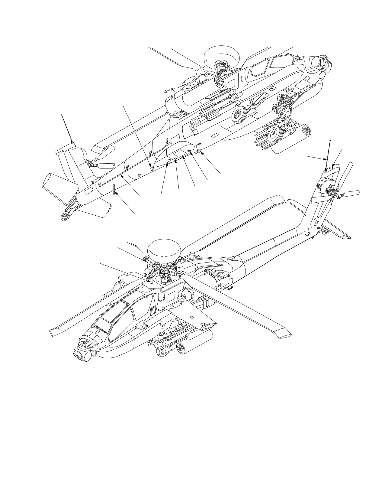
TM 1-1520-251-10
1
3
2
8
7
6
5
9
11
10
4
1. UHF
6. RADAR DOPPLER
2. VHF−AM/FM1 WHIP
7. RADAR ALTIMETER RECEIVER
3. GLOBAL POSITIONING SYSTEM (GPS)
8. VHF−FM2
4. UPPER TRANSPONDER
9. ADF
5
RADAR ALTIMETER (TRANSMITTER)
10. LOWER TRANSPONDER
11. HF
LBA5082
Figure 3A-1. Communication/Navigation Antennas
Use or disclosure of this information is subject to the restriction(s) on the title page of this document.
Change 2
3A-5
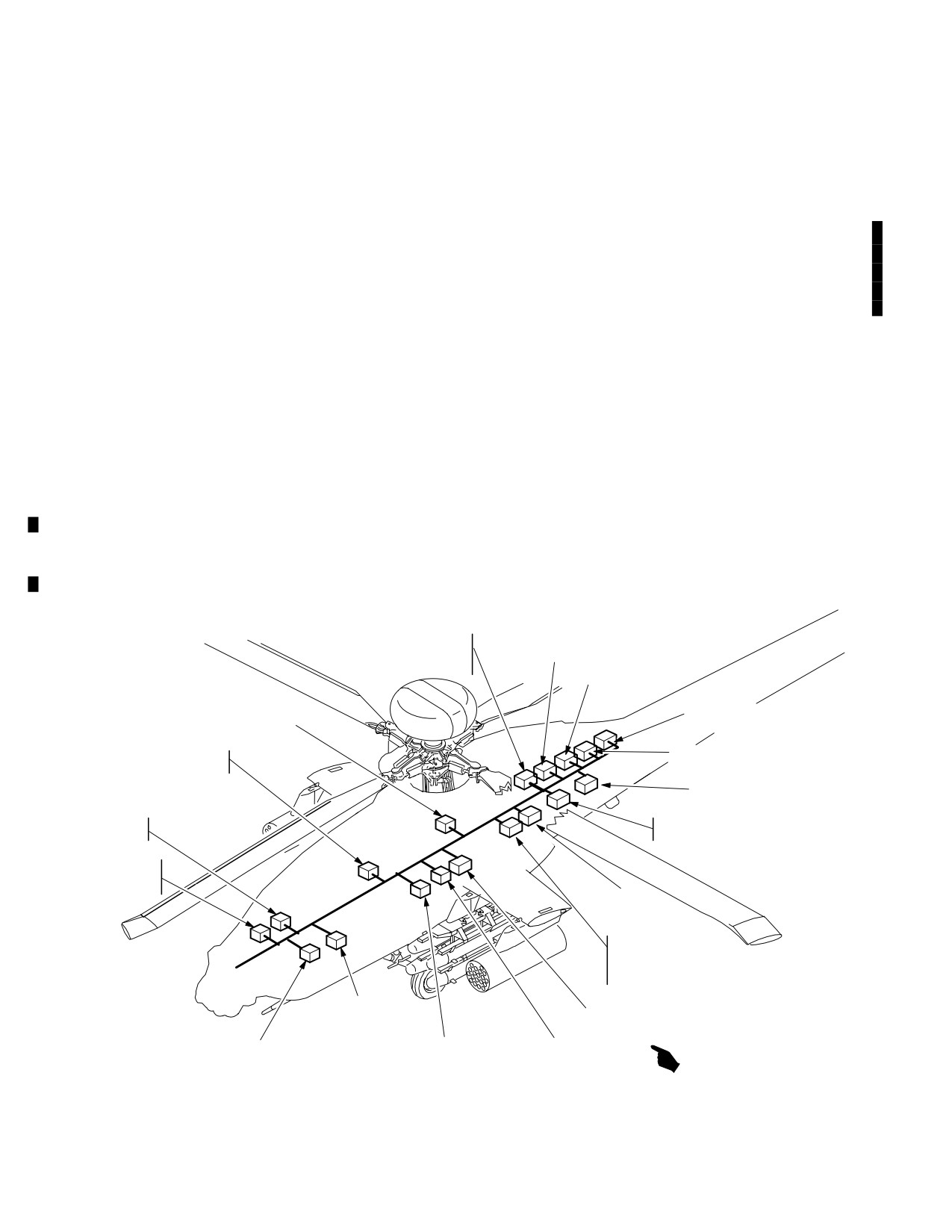
TM 1-1520-251-10
Section II. COMMUNICATIONS SUBSYSTEM
3A.4 INTRODUCTION
• MD-1295/A Improved Data Modem (IDM)
• Load Maintenance Panel (LMP) (COMSEC)
This section covers the description and operation of the
aircraft communication subsystem and the Transponder/
NOTE
IFF subsystem (fig 3A-2). Both voice and digital commu-
The APX-100(V) Transponder or
nications are supported by the following equipment:
APX-118(V) may be installed. If
APX - 100(V) is installed, Kit - 1C computer
• ARC-186(V) VHF-AM Radio Set
must be installed for Mode 4 operation.
• ARC-164(V) UHF-AM Radio Set (HAVEQUICK)
Each crewstation provides the crew with independent
• TSEC/KY-58 (CIPHER DEVICE)
control and status monitoring of the communication sub-
system via the Multi - Purpose Display (MPD), Enhanced
• ARC-201D VHF-FM (SINCGARS) 2 each
Up Front Display (EUFD), and Keyboard Unit (KU). In
• IFM-101A/AM-7189A/ARC Improved FM (IFM)
addition, monitor select and volume/squelch controls for
Amplifier
each of the five radios are controlled by the COMM panel
in each crewstation. The communication subsystem
• ARC-220 HF Radio Set
equipment is powered from the battery bus and defaulted
to ON when power is applied. However crew control of the
• TSEC/KY - 100 (HF CIPHER DEVICE)
radios is limited until aircraft or external power is applied.
• APX-100(V) Transponder
After aircraft power has been applied to the MPDs, rapid
initialization of the radio presets and Signal Operating In-
or
structions (SOI) can be accomplished via the Data Trans-
• APX-118(V) Transponder
fer Unit (DTU).
AM1789A/ARC
ARC−186
IMPROVED FM
VHF−AM RADIO
AMPLIFIER
ARC−201D (FM2)
VHF−FM RADIO
SYSTEM
PROCESSOR q2
HF POWER AMPLIFIER
COUPLER
ARC−201D (FM1)
DATA TRANSFER
UNIT
VHF−FM RADIO
ARC220 HF RADIO
DISPLAY
ARC−164
PROCESSOR q2
UHF−AM RADIO
COMMUNICATION
INTERFACE
UNIT (CIU)
KY−58/TSEC
PROCESSOR
SECURE VOICE
KY−100/TSEC
PROCESSOR
SECURE VOICE / DATA
KIT−1C/TSEC
MD1295/A
IMPROVED DATA
TRANSPONDER
MODEM (IDM)
COMPUTER (WITH APX100)
SYSTEM
DISPLAY
APX−100(V) OR APX118(V)
PROCESSOR q1
PROCESSOR q1
IFF TRANSPONDER
LBA5080A
Figure 3A-2. Communications Subsystem
Use or disclosure of this information is subject to the restriction(s) on the title page of this document.
3A-6
Change 3
TM 1-1520-251-10
3A.5 ARC-186(V) VHF-AM RADIO SET
a. Time of Day (TOD). The TOD is synchronized to
the radio clock, which is normally set to Coordinated Uni-
versal Time (UTC). The TOD is required by the radio to
The aircraft has one ARC-186 VHF radio which provides
maintain its internal clock, which controls the FH timing.
two-way communication over VHF-AM frequency range
The crew may send or receive the TOD signal if FH com-
(116.000 through 151.975 MHz) in 0.025 MHz channel
munication is desired through non - TOD synchronized ra-
spacing.
dios. Receiving the TOD affects only the internal clock of
the UHF radio.
NOTE
b. Word of Day (WOD). The WOD is classified and
ARC-186 FM frequencies (30.000 through
controlled by the National Security Agency (NSA). The
87.975 MHz) are not implemented. See
WOD programs the FH pattern and rate. The radio cannot
paragraph 3A.8
function in the FH mode without a valid WOD. A WOD is
required for each day and consists of up to six segments,
3A.5.1 VHF Tone. Selecting the VHF TONE button will
which code the radio for FH. For HaveQuick 2 radios, the
not generate a tone from the radio but will transmit a ”dead
WOD must be tagged with its operational day (1-31). The
carrier” over the air for maintenance.
WODs are loaded into the radio through the DTU or by the
crew.
3A.6 ARC-164(V) UHF-AM RADIO SET (HAVE
c. Net Number. The net number programs the radio
QUICK)
to operate in one of the FH modes, selects the frequency
table to be used and determines entry point into the FH
The aircraft has one ARC-164 UHF radio which provides
pattern. Net numbers enable multiple station pairs to op-
two-way communications over UHF-AM frequency range
erate simultaneously using the same WOD and TOD with-
(225.000 through 399.975 MHz) in 0.025 MHz channel
out interference. The net number will be loaded into the
spacing. The radio contains a separate, dedicated guard
radio through the DTU or via the crew.
receiver fixed tuned to 243.000 MHz, thus providing capa-
bility to simultaneously monitor guard frequency (243.000
3A.6.2 UHF Tone. Selecting the UHF TONE button
MHz) while receiving and transmitting on any frequency
generates an audio tone from the radio and transmits the
other than 243.000 MHz. When the transceiver is tuned to
tone over the air.
243.000 MHz, the dedicated guard receiver is automati-
cally turned OFF. The radio set has squelch capability and
3A.7 TSEC/KY-58 VOICE SECURITY SYSTEM
can operate in either single channel or frequency hopping
mode. The frequency hopping capability of the UHF radio
The aircraft has one TSEC/KY-58 Voice Security System
is referred to as HAVE QUICK. There can be one of two
for the UHF radio, which provides encrypted communica-
versions of HAVE QUICK radios installed in the aircraft.
tion. The TSEC/KY-58 has the capability to store up to six
HAVE QUICK 1 radios provide the capability to load one
Crypto Net Variables (CNV). CNVs are COMSEC vari-
word of day into the radio and utilize 6 training frequencies
ables required to establish the encryption process inside
for the training mode. HAVE QUICK 2 radios provide the
the TSEC/KY-58. CNVs are generally loaded directly into
capability to load up to six words of the day into the radio
the TSEC/KY-58 with a fill device by the maintenance
and utilize 16 training frequencies for the training mode.
crew at the Remote Selectable Fill Port, but may also be
loaded through RF Link. TSEC/KY-58 controls are imple-
3A.6.1 Frequency Hopping (FH) Capability (HAVE
mented on the MPD and/or the EMERGENCY Panel and
QUICK). The FH capability is an Electronic Counter-
the LMP.
Counter Measure (ECCM) enhancement to the standard
UHF radio by which the frequencies being used and the
3A.7.1 KY-58 Tones. The KY-58 generates tones for
dwell times are rapidly changed many times a second.
variable loading and failure conditions. An additional tone
The radio requires three items to determine the FH pat-
is generated when the KY-58 is ready to transmit or re-
tern:
ceive.
Use or disclosure of this information is subject to the restriction(s) on the title page of this document.
Change 3
3A-7
TM 1-1520-251-10
NOTE
3A.9 IMPROVED FM (IFM)
The FM radios can take as long as 10.0 sec-
The aircraft has one IFM amplifier to vary the RF power
onds to completely tune/configure to a COM
output of the FM1. The four power levels are listed in
preset. the FM radios are available for voice
Table 3A-2.
transmission within 2.0 seconds of tuning
but the transmissions may be broken.
Table 3A-2. RF Output Levels
Power Setting
Effective Radiating Power (Watts)
3A.8 AN/ARC-201D VHF-FM SINGLE CHANNEL
GROUND & AIRBORNE RADIO SET (SINCGARS)
LOW
2.5
The aircraft has two ARC-201D VHF-FM radios with Soft-
NORM
10.0
ware Improvement Program (SIP) enhancements. The ra-
dio sets provide two-way communications over the VHF-
HIGH
40.0
FM frequency range of 30.000 through 87.975 MHz in
OFF
10.0
0.025 MHz channel spacing. The radio set operates in ei-
ther single channel or frequency hopping (FH) mode. The
The communications subsystem provides capability to set
two ARC-201D radios are referred to as FM1 and FM2 or,
IFM Power to LOW /NORMAL /HIGH /OFF via the MPDs.
in general, as FM. Secure voice/data communications are
provided by COMSEC equipment which is embedded in
the radios. Each SINCGARS - SIP radio (FM1/FM2) has a
Carrier Sense Multiple Access (CSMA) line installed that
CAUTION
communicates directly with the IDM. The CSMA connec-
tion with the IDM is required for Joint Variable Message
• The IFM should be turned OFF when
Format (JVMF) communications over Tactical Internet (TI)
operating the radios on battery power
and Fire Support (FS) Protocols. The CSMA supports ad-
to avoid draining the aircraft battery.
vanced net monitoring (Net Access Delay) capabilities
• Transmitting IFM in HIGH while both
and is used to report the ARC - 201D’s configuration status
FMs are tuned to the same frequency
to the IDM whenever a TI or FS preset - net is tuned.
may cause damage to the FM2 receiv-
3A.8.1 Frequency Hopping (FH) Capability. This en-
er.
hancement provides a FH capability (frequencies and
NOTE
dwell times are rapidly changed many times a second).
Failure of the IFM will turn off the sidetone
FH provides an anti-jamming capability which can operate
from the ARC-201D FM1 radio. An IFM fail-
in conjunction with a secure communications mode. Zer-
ure is also reported during radio IBIT. The
oizing the individual radio can be accomplished from the
FM1 radio may still be able to transmit at its
MPD. Three items required to determine FH patterns are:
own internal power of 10 Watts. Should an
a. Time. Time is in the form: day, hour, and minutes.
IFM failure occur it is recommended to turn
Time is required by the radio to maintain its internal clock,
IFM off.
which controls FH timing.
3A.10 AN/ARC-220 HF RADIO SET
b. Hopset. The Hopset is classified and controlled
The aircraft has one ARC-220 HF radio. The ARC - 220
by the NSA. The Hopset programs frequency hopping
provides High Frequency airborne communications in the
rate and frequency hopping pattern. The range of Hopsets
2.0000 through 29.9999 MHz frequency range, in 0.1 kHz
is between 001 - 999. There are up to six Hopsets loaded
spaced steps. The ARC-220 operates in the following
into the radio. Hopset information can be inserted locally
modes:
through the fill device with control provided by the load
• Manual tuning
maintenance panel (LMP) and connected via the remote
selectable FILL port. It can also be distributed by Radio
• Preset Channel tuning
Frequency (RF) link also known as ECCM Remote Fill.
• ALE (Automatic Link Establishment)
• ECCM Frequency Hopping
c. Lockout Set. During frequency selection for the
Hopsets, it may be determined that interference may re-
• Emergency
sult between two nets using the same frequency. In this
The Emergency mode is a preprogrammed configuration
case one of two types of lockouts, common or unique, is
of the ARC- 220 radio. The ARC - 220 radio will be referred
automatically loaded when the system locally filled or
to hereinafter as the HF radio. Refer to Table 3A-3 for HF
through an ECCM Remote Fill.
advisory and status messages.
Use or disclosure of this information is subject to the restriction(s) on the title page of this document.
3A-8
Change 3
TM 1-1520-251-10
Table 3A-3. HF Radio Advisory/Status Message
XMIT READY
Radio has transmitted ECCM
Table
preamble and is ready to transmit.
Advisory/Status
Description
ZEROIZED
Radio is being zeroized.
Message
ANT TUNING
Radio is tuning the antenna
3A.11 KY - 100 HF RADIO COMMUNICATION
SECURITY SYSTEM
ANT UNTUNED
Radio ECCM net is not pre - tuned
CALLING
An ALE call is being transmitted
The aircraft has one TSEC/KY - 100 Communications Se-
curity System which provides encrypted communications
CALL FAILED
ALE call has failed on all attempts.
for the HF radio. The TSEC/KY-100 transforms voice,
digital data, or analog data into ciphertext information.
CALL RESPND?
ALE call detected: however, radio
The TSEC/KY - 100 has the capability to store up to six
set to SILENT mode, crew must
press PTT to establish call.
Crypto Net Variables (CNV). CNVs are COMSEC vari-
ables required to establish the encryption process inside
CHECK MSG
Radio received text message: can
the TSEC/KY-100. CNVs are generally loaded directly
be reviewed and/or deleted.
into the TSEC/KY - 100 with a fill device at the Remote Se-
lectable Fill Port, but may also be loaded through RF Link.
FILL CHECK
Radio is checking fill data.
TSEC/KY - 100 controls are implemented on the MPD.
FILL PROCESS
Radio is processing fill data.
3A.12 APX-100 TRANSPONDER
FILL RECVING
Radio is receiving fill data.
FILL WAITING
Radio is waiting for fill data.
The aircraft contains one transponder, an APX-100 or
APX - 118 (para 3A.12A), which provides automatic radar
GO DATA ONLY
Transmission quality poor, should
identification of the aircraft to all suitably equipped sta-
switch to data transmission only.
tions. The transponder receives, decodes, and responds
to interrogation of the following modes:
LINKED
ALE link established
PP RECEIVED
Radio received a present position
MODE 1
Provides 32 possible code
report; can be stored or deleted.
combinations that can be selected
RECVING CALL
Incoming ALE call being received.
in-flight. Possible code combinations
are: 00-03, 10-13, 20-23, 30-33, 40-43,
RECVING DATA
Radio is receiving digital data.
50-53, 60-63, and 70-73.
MODE 2
Provides 4096 possible code
SOUNDING
Radio is sounding.
combinations. The desired code must
SENDING DATA
Radio is sending digital data.
be set on the ground on the APX-100
located behind access panel L160.
SENDING TIME
Radio is sending the current time.
Possible code combinations are
0000-7777.
STANDBY
Radio is in standby mode.
MODE 3/A Provides 4096 possible code
SYNCING
Radio is synchronizing.
combinations that can be selected
in-flight. Possible code combinations
TIME SYNC
Synchronized time between radios
are 0000-7777.
FAIL
has failed
MODE C Provides altitude information obtained
UNSYNC
Radio is currently not synchronized.
from the FMC.
Use or disclosure of this information is subject to the restriction(s) on the title page of this document.
Change 3
3A-9
TM 1-1520-251-10
NOTE
3A.12A APX-118 TRANSPONDER
• KIT - 1C is not required in the aircraft with
The APX - 118 provides automatic radar identification of
the APX - 118 transponder.
the aircraft to all suitably equipped stations. The trans-
ponder receives, decodes, and responds to interrogation
• When the KIT-1C is not installed in the
of the following modes:
aircraft, the MODE 4 selection will not be
shown on the MPDs.
MODE 1
Provides 32 possible code
combinations that can be selected
in-flight. Possible code combinations
3A.12.1 KIT-1C MODE 4 Computer. Provides a cryp-
are: 00-03, 10-13, 20-23, 30-33, 40-43,
to-secure mode of identification for the APX - 100 trans-
50-53, 60-63, and 70-73.
ponder, by relying on an encrypted interrogation. It utilizes
MODE 2
Provides 4096 possible code
two classified operational codes which are loaded directly
combinations. Possible code
into the KIT-1C computer via a fill device through the Re-
combinations are 0000-7777.
mote Selectable Fill Port in the aft avionics bay. Code
selection is limited to A or B, which corresponds to the op-
MODE 3/A
Provides 4096 possible code
erational day. Other MODE 4 capabilities are:
combinations that can be selected
in-flight. Possible code combinations
• When on the ground, the MODE 4 HOLD
are 0000-7777.
enables the computer to save the last
MODE 4
Provides a crypto - secure mode of
MODE 4 codes for utilization on the next
identification by relying on an encrypted
power-up.
interrogation. It utilizes two classified
operational codes which are loaded
• IDENT selection located on the MPD and
directly into the transponder via a fill
COMM panel enables IDENT transmis-
device through the Remote Selectable
sion to ID ownship on others’ radar
Fill Port in the aft avionics bay. Code
screens.
selection is limited to A or B, which
corresponds to the operational day.
• Selectable MODE 4 audio cueing.
MODE C
Provides altitude information obtained
from the FMC.
• Selectable MODE 4 EUFD visual cueing.
MODE S
Provides Aircraft Address, Aircraft Tail
Number, and the Aircraft Flight ID.
• Selectable EMERGENCY mode.
Use or disclosure of this information is subject to the restriction(s) on the title page of this document.
3A-10
Change 4
TM 1-1520-251-10
b. The IDM serves as the Tactical Internet Controller
CAUTION
Device (TICD) for aviation. It is compatible with the Force
Battlefield Command for Brigade and Below (FBCB2) de-
Failure to place the IDM in STBY mode
vice and the TI architecture. A TI/FS Carrier Sense Multi-
prior to removing aircraft power may re-
ple Access line connects both of the ARC - 201D radios di-
sult in corrupted data files or damage to
rectly to the IDM. The CSMA implementation supports:
the IDM.
• TI and FS net access and monitoring requirements
• Upon tuning the SINCGARS - FS and/or SINC-
3A.13 IMPROVED DATA MODEM (IDM)
GARS - TI frequency, the SINCGARS SIP radio(s)
configuration is reported to the IDM.
NOTE
Through the CSMA port, the IDM compares the SINC-
Testing has shown that reception ranges are
GARS radio configuration with its own configuration. If a
often degraded by five NM or more over
mismatch is detected, a white NET JOIN status is dis-
those ranges where voice communication
played on COM page while an automatic net join synchro-
can be received.
nization process is conducted. The status is removed
once the IDM and the ARC - 201D radio are synchronized.
The aircraft is configured with a single IDM, which sup-
The NET JOIN status will remain displayed in the rare
ports the digital communication requirements for Long-
case where the NET JOIN synchronization fails: the oper-
bow Air Force Application Program Development
ator may attempt another SINCGARS - FS/TI tune to re -
(AFAPD), TACFIRE, Tactical Internet and Fire Support
start the NET JOIN process.
protocols.
c. The IDM’s two major software and hardware ver-
a. The IDM serves as the digital host interface be-
sion numbers may be recalled and displayed on the DMS
tween the aircraft’s radios and the data bus for specific
VERS page. IDM’s TACFIRE software and processor
mission equipment. IDM communications occur over a
firmware versions are recalled through the following
crewmember’s selected digital radio channel, as deter-
ATHS page button tree: START page 1/3, RESET DATA>
mined by that crewmember’s EUFD IDM transmit select
page 1/1, <SW - VERS page 1/4, 2/4, 3/4, and 4/4 pages.
indicator, or the tuned FM1 or FM2 radio for Fire Support
artillery messages. Management of the IDM is performed
NOTE
through the communications subsystem.
The IDM’s hardware and software version
NOTE
numbers are not displayed on VERS page if
IDM is in STBY.
• Each crewstation is equipped with its own
unique EUFD IDM select switch and indi-
cator (fig 3A-4). A blocked diamond sym-
d. The IDM is implemented with an INHIBIT button on
bol on the left side of the EUFD format
the SET page that, when selected, inhibits all IDM radio
represents each station’s unique IDM se-
data transmissions. The IDM receives data transmissions
lect indicator.
but does not automatically respond. The INHIBIT feature
is primarily used during refuel/rearm operations.
• The opposite crew member’s EUFD IDM
select indicator (fig 3A-4) is displayed as
a filled diamond symbol. If both crew
e. Prior to removing power from the aircraft, the IDM
members have the same radio selected
button is required to be placed to STBY. In STBY, the IDM
for IDM transmit, then a filled block sym-
is no longer capable of transmitting any data messages
bol will be displayed.
and will no longer receive JVMF messages. The IDM but-
ton is located on both the DMS SHUTDOWN page and
• The IDM select indicator is not used by
SET pages.
the system when a FS preset-net is
tuned to either FM1 or FM2 and a TSD
RPT ARTY page message is sent or re-
3A.14 LOAD MAINTENANCE PANEL (LMP)
ceived.
• The IDM will delete all JVMF messages
The LMP (fig 3A-3) consists of a keypad, display, front
(TI and FS) anytime that the TI is de-
panel control switches, and knobs. It is co-located in the
tuned.
RH aft avionics bay with the Remote Selectable Fill Port.
Use or disclosure of this information is subject to the restriction(s) on the title page of this document.
Change 4
3A-11
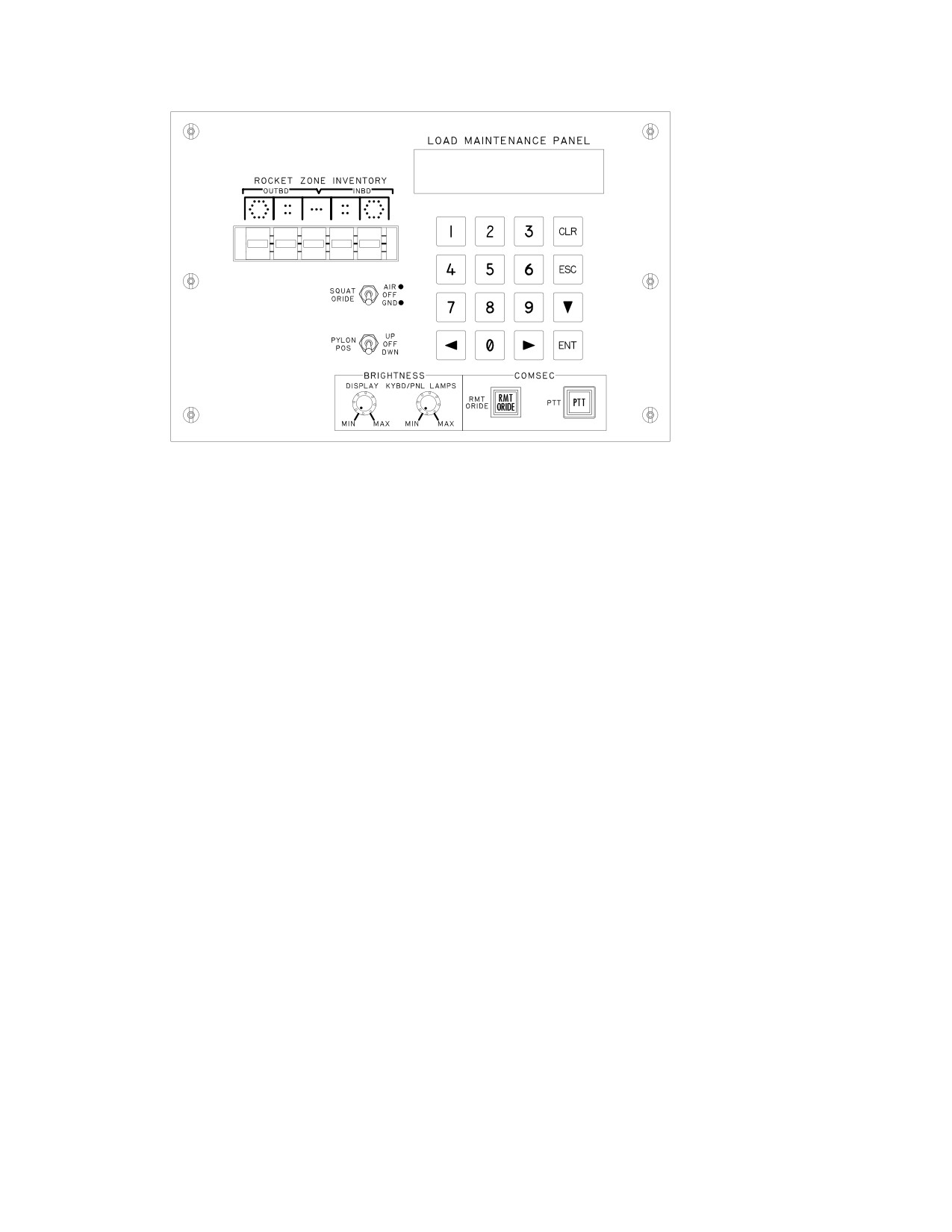
TM 1-1520-251-10
1=RADIOS
3=GUNS
2=CRYPTOS
4=ASE
1:4:
6PD
6IL
6RC
6SK
6WP
LBA5081
Figure 3A-3. Load Maintenance Panel
3A.14.1 LMP Capabilities. The LMP provides the fol-
NOTE
lowing capabilities:
ICS communication is the only recom-
mended communication during PTT opera-
• Position pylons for loading stores.
tions. Do not use UHF at this time.
• Override the SQUAT SWITCH setting to simulate
airborne conditions for troubleshooting and testing
3A.14.3 Press-To-Talk (PTT) Button. The PTT button
while on the ground.
enables the transfer of Crypto Net Variable(s) from the Fill
device to the KY-58. This CNV transfer can be initiated by
• Display and specify rocket types associated with
keying the appropriate radio from either crewstation.
each of the aircraft rocket zones.
3A.14.4 LMP Lighting. To save power, all LMP dis-
• Display and specify 30mm Gun rounds count.
plays and lamps are extinguished while airborne. After
landing, pressing any LMP keypad button reactivates the
• Display and specify Chaff count.
LMP displays and status lights. This initial key press is not
interpreted as a data entry keystroke.
• Specify data download to the FM radios.
• Specify/verify data download to the HF radios.
3A.14.5 RADIO Selections. LMP provides the capabil-
ity to select the individual radio formats (1= FM1; 2= FM2;
• Specify data download to the HF Radio’s Crypto
3= HF) for data fills and HF data verification. Selection of
device
the ESC key returns the operator to the index.
• Press-to-talk (PTT) and Remote Override (RMT
a. FM1 and FM2 Radio Fill Selections. The LMP
ORIDE) COMSEC pushbuttons.
provides for frequency hopping and COMSEC variable fill
selections via LMP keyboard. Selections are available for
3A.14.2 Remote Override (RMT ORIDE) Button. The
the following fill device capabilities:
RMT ORIDE button disables MPD control and enables
• Single Hopset Preset
front panel (KY-58) control capabilities for Crypto Net Vari-
ables loading purposes. The RMT ORIDE button is auto-
• Single Lockout Set Preset
matically disabled when the aircraft is airborne and must
• Single COMSEC variable
be manually actuated on the ground for any further load-
ing.
• Complete set of Hopset/Lockout Set/COMSEC
Use or disclosure of this information is subject to the restriction(s) on the title page of this document.
3A-12
Change 2
TM 1-1520-251-10
Single Hopset/Lockout Set/COMSEC variable filling re-
The IDM rocker permits cycling up or down through the
quires two separate fill devices. A complete set of Hopset/
displayed list of radios. Repeated momentary depression
Lockout Set/COMSEC variable filling can be achieved
of down selections beyond the last radio in the list will
with a single fill device. LMP display feedback is provided
cause the IDM indicator to start over at the top of the list.
for function in-progress, function completion, function
Repeated momentary depression of up selections beyond
PASS and function FAIL status.
the first radio in the list will cause the RTS indicator to start
over at the bottom of the list.
b. HF Radio Fill Selections. The LMP provides for
3A.15.2 Radio Transmit Select
(RTS) Rocker
keyfill, datafill, and verification selections via LMP key-
Switch. The RTS switch permits the operator to select a
board. A fill device is required for both the keyfill and data-
radio for voice transmission. The RTS switch is located on
fill. The following selections are available from the LMP
the lower left side of the EUFD, to the right of the IDM
with the HF radio option selected:
rocker switch, and below the WCA rocker switch.
• Keyfill load
The EUFD displays a filled - left - arrow character on the
• Datafill load
left side of the format for that crewstation’s RTS indicator.
the opposite crewstation’s RTS indicator is displayed as a
• Verify keys
filled - right - arrow character. The RTS rocker permits cycl-
• Verify data
ing up or down through the displayed list of radios. Re-
peated momentary depression of down selections beyond
The VERIFY KEYS selection provides status of the key
the last radio in the list will cause the RTS indicator to start
load for LP3 (cipher for ECCM) and ECCM. The VERIFY
over at the top of the list. Repeated momentary depres-
DATA selection provides status of the datafill load. A dis-
sion of up selections beyond the first radio in the list will
play of the HF MODE CHANGE FAIL message indicates
cause the RTS indicator to start over at the bottom of the
when the HF failed to change modes properly when com-
list.
manded to perform a keyfill, datafill, verify keys, or verify
3A.15.3 Preset (P) Button. The P button opens or
data. The datafill load verification and return code in-
closes the EUFD Preset Window on the EUFD display.
cludes:
The EUFD Preset Window is used to select one of ten
• PRE OP (operable), ND (no data), NK (no
single channel presets for tuning the selected voice radio.
keys)
The P button is located on the right side of the EUFD dis-
play just below the brightness BRT knob.
• LP3
OP, ND, NK
• ECCM OP, ND, NK
3A.15.4 Preset Enter button. The Preset Enter
(down - left arrow) button is used to initiate a single chan-
• MAN OP, ND, NK
nel tuning of the selected voice radio, based on the preset
• ALE
OP, ND, NK
selected indicator (i.e. arrow symbol) in the EUFD Preset
Window. The Preset Enter button is located to the right of
• EMER OP, ND, NK
the P button, and above the Swap button.
3A.14.6 LMP CRYPTO Selection. The LMP CRYPTO
3A.15.5 Swap Button. The Swap button permits the
selection provides the capability to access the formats for
exchange (”swapping”) of the standby frequency/mode,
selecting the installed individual crypto devices for key
call sign, and net type with the primary frequency/mode,
fills.
call sign, and net type for the currently - selected radio as
displayed in the EUFD. In addition to the swapping of
3A.15 UP FRONT DISPLAY (EUFD)
data, the system will automatically tune a frequency and
COMMUNICATION CONTROLS
reconfigure the corresponding radio and IDM when the
net type is L (Longbow AFAPD), T (TACFIRE), I (Tactical
EUFD communication controls (fig 3A-4) are as follows:
Internet) or F (Fire Support). The swap button, with two
“turning arrows” is located to the right of the stop watch
3A.15.1 IDM Rocker Switch. The IDM switch permits
button and below the preset enter button. The standby fre-
the operator to select a tuned radio for IDM data message
quency/mode, call sign, and net type is located on the
transmission. The IDM switch is located on the left side of
right side of the display and the primary frequency/mode,
the EUFD, centered, to the left of the RTS and WCA rock-
call sign, and net type for the current RTS radio is dis-
er switches.
played on the left side of the display.
Use or disclosure of this information is subject to the restriction(s) on the title page of this document.
Change 2
3A-13
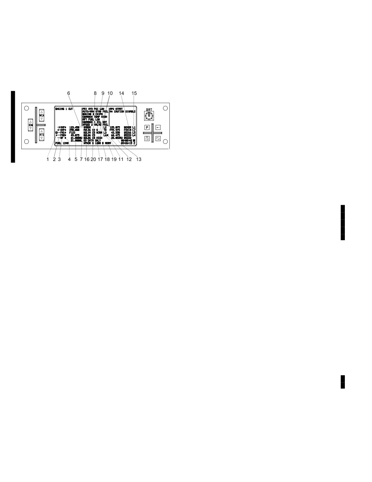
TM 1-1520-251-10
3A.16 EUFD COMMUNICATIONS DATA FORMAT
• When SINCGARS is in Frequency Hopping mode,
the Active Hopset is displayed in the correspond-
The EUFD displays a select subset of current status infor-
ing EUFD FM Current Frequency location in the
mation of the communication subsystem, in the lower half
form Fxxx, where xxx is the Hopset ID.
of the display (fig 3A-4).
6.
Call Sign (EUFD primary) currently assigned to
the currently tuned radio: MAN = manual tune;
GUARD = Guard tune
7.
HF radio status (Table 3A-3).
8.
Cipher Off/On status and Crypto Net Variable
(UHF, FM 1, FM 2, and HF only).
9.
Guard (G) receiver Off/On (UHF only).
LBA5031A
10.
Power status. IFM power status includes OFF,
LOW, NORM, HIGH. HF power status includes
LOW, MEDIUM, HIGH.
Figure 3A-4. EUFD Data Format
11.
IDM Net status (I = Internet, F = Fire Support, L
= Longbow {AFAPD}, and T = Tacfire).
EUFD communications symbology, used in the display
fields (fig 3A-4) are numbered as follows:
12.
Tactical Internet Connected indicator. Presence
of a filled circle superimposed with an X indi-
1. The EUFD displays a blocked diamond symbol
cates that preset is tuned to the Tactical Internet
in the left - most field of the display for that
(I) protocol and the TI radio is connected to the
crewstation’s IDM (transmit/receive) indicator.
TI - Network.
The opposite crewstation’s IDM indicator is dis-
played as a filled diamond symbol. If both crew
13.
Standby (last tuned) frequency/FH parameters.
members have the same radio selected for IDM
data transmission, then a filled block symbol will
14.
Standby Call Sign is a previously tuned preset
be displayed.
that is now passively resident in the EUFD’s
standby area until swapped back to primary.
2. The EUFD displays a left - pointing arrow symbol
in the second field for that crewstation’s RTS
15.
Standby IDM Net Status (I, F, L, or T)
(transmit/receive) indicator. The opposite
crewstation’s RTS indicator is displayed as a
16.
Transponder identifier.
right - pointing arrow symbol. Dots (no arrow) in-
17.
Transponder Mode 3/A status and code.
dicate that the radio is enabled for monitoring
(receiving) only.
18.
XPNDR Mode 4 code. Presence of code indi-
cates Mode 4 is On.
3. Radio identifier (VHF, UHF, FM1, FM2 or HF ).
19.
Transponder Master Control (STBY/NORM/
4. Squelch Off/On status (asterisk indicates
EMER) status.
squelch On).
20.
XPNDR Mode S enable/disable status which is
5. Currently tuned frequency/FH parameters.
only displayed if an APX - 118 is installed.
• When the UHF radio is in Frequency Hopping
3A.17 COMMUNICATIONS (COMM) PANEL
mode, the UHF frequency displayed on the EUFD
is an ’F’ followed by the net number. When in the
There is a COMM panel (fig 3A-5) in each crewstation to
Training mode, the UHF frequency displayed on
provide volume control and other functions for the respec-
the EUFD is a ’T’ followed by the training net
tive crewstation. Following is a description of the COMM
number.
panel controls:
Use or disclosure of this information is subject to the restriction(s) on the title page of this document.
3A-14
Change 4
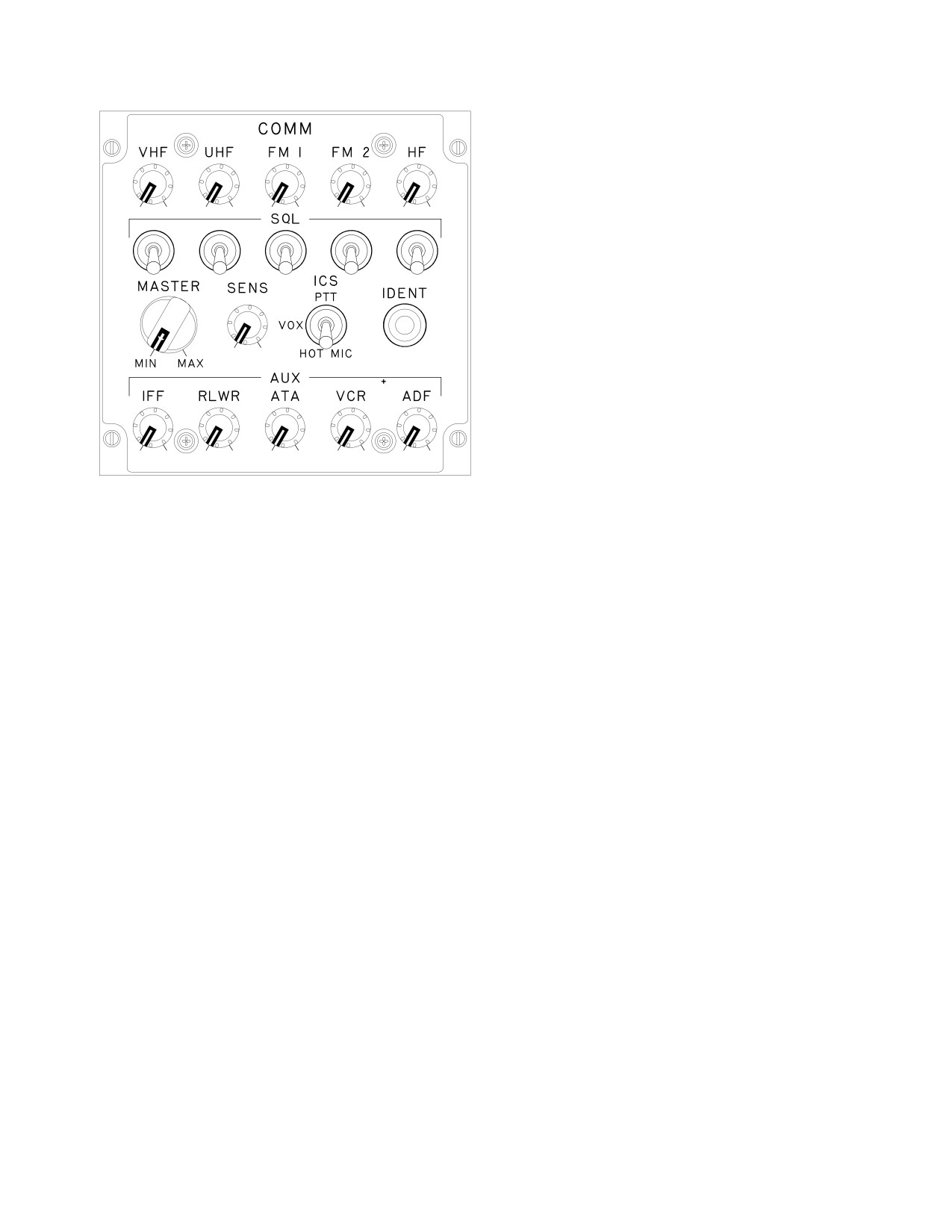
TM 1-1520-251-10
3A.17.5 ICS Mode Switch. The ICS mode switch pro-
vides selection of the audio keying system for commu-
nication between crew stations. Following are the three
modes that can be selected with the ICS switch:
ÑÑÑÑÑ
ÑÑ
ÑÑÑÑÑ
ÑÑÑÑÑ
ÑÑ
ÑÑÑÑÑ
a. Push-To-Talk (PTT). The PTT position allows
communication only while the ICS PTT switch is being de-
pressed.
ÑÑ Ñ
b. VOX. The VOX position allows communication
between crewmembers only when their voice levels ex-
ÑÑÑ
ÑÑÑ
ceed the threshold level as set with the SENS control.
ÑÑ
ÑÑÑ
c. HOT MIC. The HOT MIC position allows continu-
ous communication between crewmembers.
ÑÑÑÑÑ
ÑÑ
ÑÑÑÑÑ
ÑÑÑÑÑ
ÑÑ
ÑÑÑÑÑ
3A.17.6 IDENT Switch. The IDENT switch allows the
transponder to be placed in IDENT mode. This switch per-
LBA0072
forms the same function as the IDENT option label located
on the MPD XPNDR page.
Figure 3A-5. Communications (COMM) Panel
3A.17.7 AUX Controls
a. Identification, Friend or Foe (IFF). The IFF
3A.17.1 Volume Controls. The top row of five knobs
knob provides independent volume control of the IFF
provide independent volume control for the respective ra-
MODE 4 audio.
dios. Monitoring of the radios, VCR, and ADF audio can
be disabled by pulling out the respective control knob
b. Radar/Laser Warning Receiver (RLWR). The
which removes the appropriate monitor status dot from
RLWR knob provides independent volume control of the
the EUFD, unless selected as the active transmitter.
RLWR audio.
3A.17.2 Squelch (SQL) Switches. The SQL switches
c. Air - To - Air (ATA). This knob is not currently
are momentary toggle switches that provide squelch on/
used.
off capability. There is a SQL switch for each radio, lo-
cated directly below the corresponding volume control
d. Video Cassette Recorder (VCR). The VCR
knob.
knob provides independent volume control of the VCR
playback audio.
3A.17.3 MASTER Control. The MASTER control pro-
vides the capability to adjust the audio level (volume) of all
e. Automatic Direction Finder (ADF). The ADF
signals associated with the communication subsystem
knob provides independent volume control of the ADF au-
and controls the applicable crewstation helmet and wing
dio.
connection volume levels.
3A.18 EMERGENCY PANEL
3A.17.4 Sensitivity (SENS) Control. The SENS con-
trol provides the capability to adjust the audio threshold
level when the ICS mode switch is in the VOX position.
The EMERGENCY panel (fig 3A-6) communications func-
The system only transmits when voice level exceeds the
tions provides for tuning the UHF radio to the GUARD fre-
threshold setting of the SENS adjustment. To increase
quency, selection of the transponder (XPNDR) emergen-
sensitivity rotate control clockwise.
cy mode, and zeroizing classified data.
Use or disclosure of this information is subject to the restriction(s) on the title page of this document.
Change 2
3A-15