HELICOPTER, ATTACK, AH-64D LONGBOW APACHE. TECHNICAL MANUAL (2002) - page 7
TM 1-1520-251-10
c. FM1 and FM2 lockout sets.
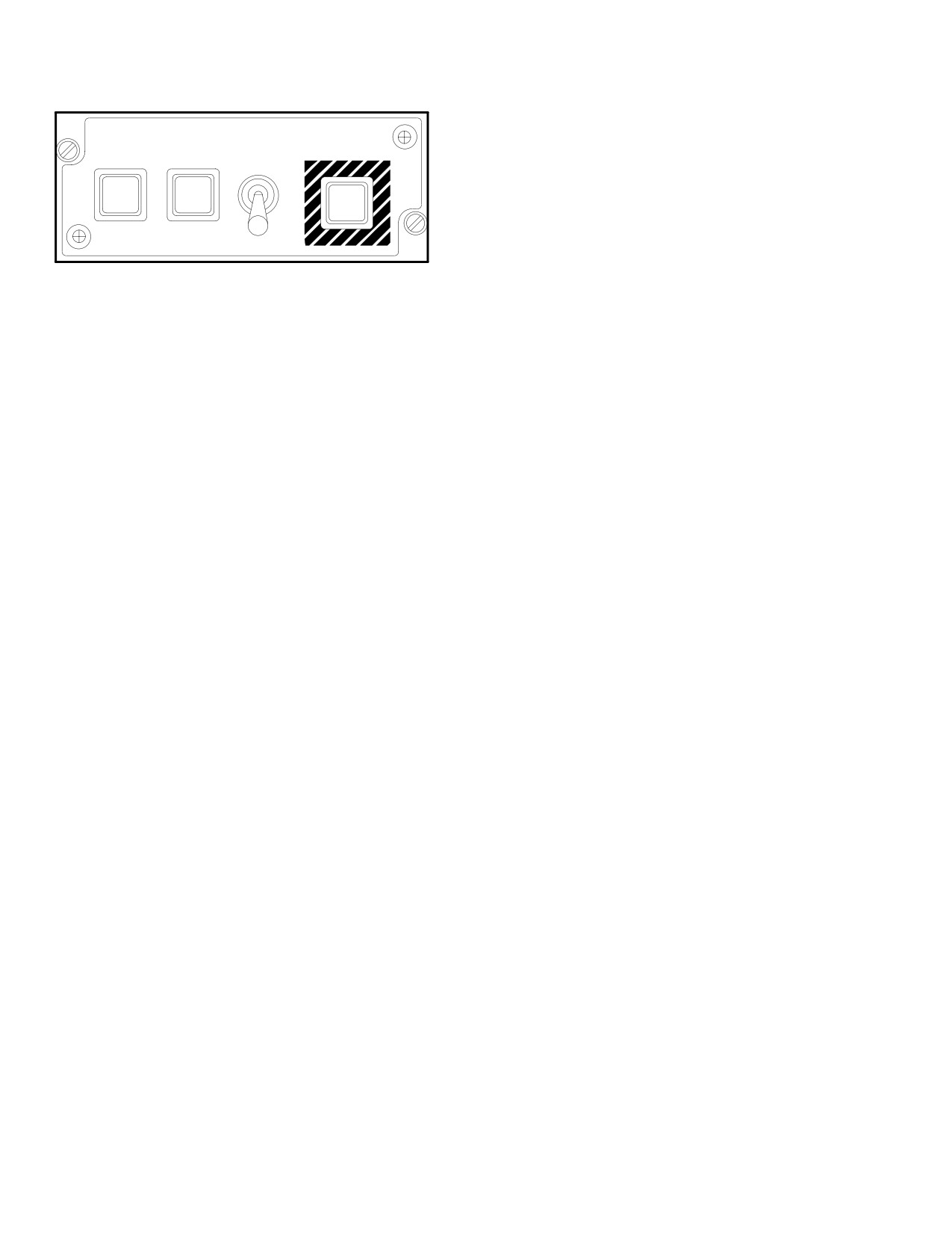
EMERGENCY EMERG
HYD
GUARD
XPNDR
ZEROIZE
d. HF radio.
ON
ON
e. HQ1 WOD or HQ2 MWOD from radio, and SP
ON
Non - Volatile Memory (NVM).
f. All Signal Operating Instructions (SOI) tables/data
in Data Processor (DP) NVM.
LBA2448
g. Mode 4 (KIT-1C).
Figure 3A-6. EMERGENCY Panel
h. IDM network parameters.
3A.18.1 GUARD Lighted Button. Pressing this button
tunes the UHF radio to its guard frequency, which is dis-
i. IDM team member indications in the IDM and DP
played on the EUFD, and causes the system to automati-
NVM.
cally select (RTS) the UHF radio. Pressing the GUARD
button again commands the system to swap the primary
j. Tactical Situation Display (TSD) Waypoints, Tar-
and standby locations of the EUFD: 1) the guard frequen-
gets/Threats, and Control Measures.
cy is swapped into the EUFD’s standby frequency loca-
tion; and 2) the radio and/or preset - net data previously in
NOTE
the standby location is swapped back into the EUFD’s pri-
mary location.
• Emergency zeroize does not erase clas-
sified data in the FCR and DTC
3A.18.2 XPNDR Lighted Button. Pressing this button
sets a code of 7700 in mode 3/A. The XPNDR Mode 3/A
3A.19 CYCLIC GRIP COMMUNICATIONS CONTROLS
button has to be moded ON and XPNDR MASTER button
can be in NORM or STBY prior to activating the XPNDR
The cyclic control grips provide the crew with the RADIO/
emergency button. The EUFD provides a status of 7700
ICS Push-To-Talk (PTT) switch and the Radio Transmit
EMER to indicate that emergency transponder mode has
Select (RTS) switch.
been selected. To exit the emergency transponder mode,
press the XPNDR button again, which will extinguish the
3A.20 ICS/RADIO FOOT CONTROLS
light. After deactivation, the system does not reset any
codes until they are entered manually or with the Data
CS/Radio foot controls are identical for both crew stations
Transfer Cartridge (DTC).
and are located on the forward crew station deck. The ra-
dio PTT foot control is located on the left side of the crew
3A.18.3 ZEROIZE Switch. The ZEROIZE switch is ac-
station. The ICS PTT foot control is located on the right
tioned by first pulling it up and out of the locked position,
side of the crew station.
next to the forward position, and then returning the switch
to the locked or after position to complete the zeroization
3A.21 COMMUNICATION SUBSYSTEM DISPLAY
process. Actioning the ZEROIZE switch zeroes-out the
FORMAT OVERVIEW
following classified data:
The Communication Subsystem controls and displays are
a. COMSEC variables.
accessed through the MPDs in each crew station. The
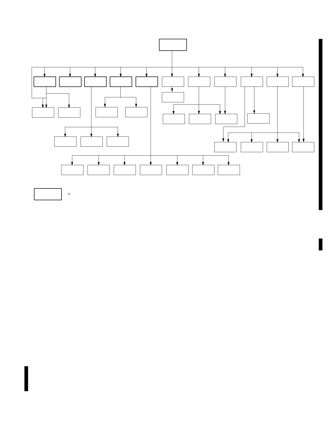
paging tree (fig 3A-7) illustrates the structure of the COM
b. FM1 and FM2 Hopsets.
subsystem pages.
Use or disclosure of this information is subject to the restriction(s) on the title page of this document.
3A-16
Change 2
TM 1-1520-251-10
COM
PRESET
ORIG
MSG
MSG
IDM
XPNDR
UHF
FM
HF
MAN
NET
EDIT
ID
SEND
REC
SOI
PRESET
EXPND
ERF
SET
DIR
MBR
ORIG
SUFFX
MODEM
DIR
DIR
WOD
FMT
SET
CURRENT
IDM
TEXT
ATHS
MISSION
SELF
NETS
NETS
CALL
PRESETS
SET
ZERO
ADDRESS
(ALE)
(ECCM)
ADDRESS
Available from MENU Page
LBA5067B
Figure 3A-7. COM Subsystem Paging Tree
3A.22 COMMUNICATIONS PROTOCOL AND
networks; 6) BDE MULTICAST , when operating over TI;
NETWORKS
and 7) Unit Task Organization, when operating over TI.
The following communications protocol and network ter-
NOTE
minologies are used throughout this section:
• Tactical Internet Enhanced Position
Location Reporting System (EPLRS) BN/
3A.22.1 Originator ID. The unique digital identification
BDE Wide Network refers to a battalion/
of the ownship or a formal leadership role entity associat-
brigade multicast group that employs the
ed with the ownship. Digital ID’s include: 1) LONGBOW;
EPLRS - Radio Set as the net’s digital ra-
2) TACFIRE; 3) TACTICAL INTERNET {TI}; and 4) FIRE
dio
SUPPORT {FS}.
• The Tactical Internet SINCGARS Stub
Network is a SINCGARS Software Im-
NOTE
provement Program (SIP) network that is
An entity is any single platform, system,
“stubbed” into the EPLRS network
leadership role position, staff role position,
through a gateway; also referred to as a
etc. that has an assigned digital ID relation-
“Roamer Net”
ship.
3A.22.3 Member. A member, or subscriber, is a single
3A.22.2 Network. A functionally related group of mem-
member or station assigned to a network. Each digital
bers that are assigned and configured with a common: 1)
member entity is assigned a unique digital identification.
radio type; 2) SC frequency, or HOPSET/ECCM ID; 3) call
Digital ID’s include: 1) LONGBOW; 2) TACFIRE; 3) IN-
sign; 4) crypto key, when required; 5) protocol, for digital
TERNET {TI}; and 4) FIRE SUPPORT {FS}.
Use or disclosure of this information is subject to the restriction(s) on the title page of this document.
Change 4
3A-17
TM 1-1520-251-10
3A.22.4 Team Member. A team member is a network
3A.22.11 Unit Task Organization (UTO). The UTO is
member designated to receive Longbow, Tacfire, Tactical
the Tactical Internet’s instruction for how the IDM con-
Internet, or Fire Support team messages. Each digital net-
nects to any of the various entities within a division. The
work may contain up to 16 team members (including own-
UTO is organized around the structure of a division and its
ship).
subordinate organizations in terms of entities within actual
units such as entity personnel, entity equipment, and the
absolute TI data associated with all the unique entities.
3A.22.5 Primary Member. A primary member is a net-
The IDM’s current TI UTO is displayed on the ORIG ID or
work member designated to receive primary messages
MSG SEND/RCV IDM SET page.
from the TSD RPT page over a Longbow net, Tactical In-
ternet or Fire Support net. There are a maximum of 8 pri-
3A.22.12 SINCGARS Gateway. The gateway is used
mary members (including the ownship) per digital network
by some ground element SINCGARS SIP platforms (only
(1-10). A net member does not have to be a team member
an unspecified amount of ground elements) to connect to
to be a primary member.
the Tactical Internet’s battalion EPLRS or brigade EPLRS
wide network. The SINCGARS gateway is composed of a
SINCGARS SIP radio linked, through an Internet Control-
3A.22.6 Tactical Internet (TI). An automated, router -
ler Card (INC), to an EPLRS - Radio Set. The mission of
based communications network protocol that employs
the gateway is to connect (”stub”) SINCGARS SIP TI ra-
commercial internet standard protocols to move Joint
dios to the Tactical Internet’s BN or BDE EPLRS wide net-
Variable Message Format data vertically and horizontally.
work.
The TI is comprised of two parallel messaging compo-
nents: 1) Situational Awareness messaging; and 2) Com-
mand and Control messaging.
NOTE
• The SINCGARS gateway is also com-
3A.22.7 Fire Support (FS). A point to point JVMF MIL -
monly referred to as either a “Stub Net
STD - 220B protocol, independent of the Tactical Internet,
Gateway” or “Roamer Net Gateway
designed to meet real time point - to - point artillery mes-
sage requirements. The FS protocol is being phased in as
• Army Aviation exclusively utilizes EPLRS
the successor to the legacy TACFIRE protocol. The
or BFT to connect to the actual TI net-
AH-64D supports the artillery’s quick fire net protocol
work.
which is comprised of three additional elements: 1) AC-
• The Enhanced Position Location Report-
CESS RANK; 2) TOTAL STATIONS; and 3) STATION ID.
ing System (EPLRS) provides a secure,
near real - time, jam resistant, data com-
3A.22.8 Unit Reference Number (URN). The digital ID
munications capability
associated with TI, and FS member entities and MultiCast
• An EPLRS network consists of a number
Groups (MCG). A valid URN could range from 1 through
of EPLRS Radio Sets (EPLRS - RS) con-
16,777,215.
trolled by an EPLRS Net Control Station
(EPLRS - NCS)
3A.22.9 Multicast. Used by the IDM to send a single TI
3A.22.13 Situational Awareness
(SA) Report-
JVMF message (size limited) to the ownship’s MCG. Mul-
ing. When tuned to the TI, the default setting for the IDM
ticast is used by the IDM as a tool to reduce overall band-
is to send AUTO SA reports to a SA server as determined
width demands on the TI network. The IDM controls how
by, the first occurrence of, either the preset elapsed time
each message is sent. Each digital TI battalion and bri-
or the preset distance an aircraft has moved. The SA serv-
gade has its own associated MCG Unit Reference Num-
er disseminates the SA data to all the entities that are
ber listed in the Unit Task Organization (representing a
logged in. The AUTO SA is accessed and edited from the
digital division) that resides in the IDM. The IDM does not
ORIG ID or MSG SEND/RCV IDM SET page.
require operator input of the MCG URN.
3A.22.14 Situational Awareness (SA) Receiving. When
3A.22.10 Joint Variable
Message Format
tuned to the TI, the IDM automatically updates the SA data
(JVMF). Messages with format governed by the Joint In-
periodically. Controls for the display of SA icons are located
teroperability of Tactical Command and Control Systems
on the TSD page and the SA page. SA provides different
Variable Message Format Technical Interface Design
icons to represent Friendly, Enemy, Enemy ADA, Unknown,
Plan and MIL - STD - 2045 - 47001B. JVMF messages are
and Unknown ADA. The icons are shape and color coded
currently used with the TI and FS protocols.
(see Appendix C).
Use or disclosure of this information is subject to the restriction(s) on the title page of this document.
3A-18
Change 4
TM 1-1520-251-10
3A.23 COMMUNICATIONS (COM) PAGE
• T6
HF button
• L1-L5
PRESET buttons
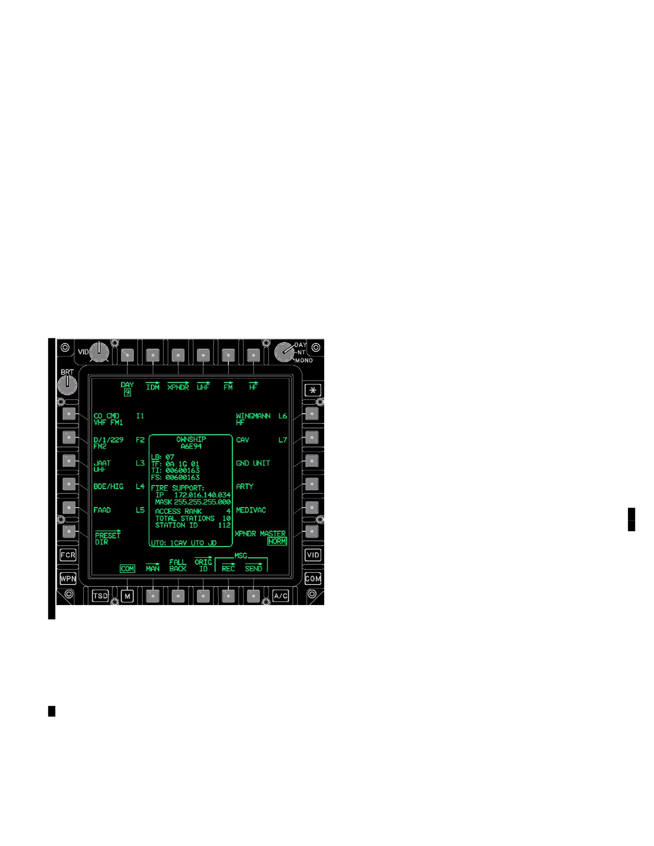
The COM page (fig 3A-8) is used to manage up to ten pre-
• L6
PRESET DIR button
set - networks. All ten (1-10) of the preset - networks, sup-
port Tactical Internet and Fire Support protocols while
• R1-R5
PRESET buttons
Longbow and TACFIRE protocols may only be used with
• R6
XPNDR MASTER button
preset - nets one through eight (1-8). Any of the ten COM
• B2
MAN button
page preset-nets may be replaced through using the
• B3
FALL BACK button
PRESET DIRectory’s preset replace function. The PRE-
SET DIR is a database capable of containing up to 60
• B4
ORIG ID button
Longbow, TACFIRE, Tactical Internet, Fire Support, and
• B5
MSG REC button
voice - only preset database items with up to 15 members
• B5
MSG SEND button
each. Selecting the COM subsystem button or the COM
page button from the MENU page displays the COM
NOTE
page. Various communication subsystem status windows
An operator change to the DAY button will
and control selections are provided by bezel buttons lo-
not detune any of the currently tuned pre-
cated along the edges of the MPD. The paging options at
set - nets; when desired, the operator is re-
the top of the page provide access to subsystem function-
quired to perform subsequent tunes to in-
al pages.
voke the new selected DAY’s data.
3A.23.1 DAY Button. The DAY button provides the ca-
pability to toggle between the two SOI days of the SOI
data that is displayed within the communications subsys-
tem. The two SOI days are numbers with a range of 1- 10.
When the operator actions the DAY button the Display
Processor updates the SOI data to the alternate day. Se-
lecting the button again will toggle the data back to the
original day. Changing the DAY button only effects a
change to the MPD data presentation, a tune or re - tune is
required to effect EUFD preset - net status changes. The
SOI day number is uploaded to the Display Processor
from the DTC as part of the Presets upload.
3A.23.2 IDM Page Button. The IDM button displays
the IDM page.
3A.23.3 XPNDR Page Button. The XPNDR button dis-
plays the XPNDR page.
3A.23.4 UHF Page Button. The UHF button displays
the UHF page.
LBA5477
3A.23.5 FM Page Button. The FM page button dis-
Figure
3A-8.
COM Page
plays the FM page.
3A.23.6 HF Page Button. The HF page button displays
Buttons on the COM page are described below:
the HF page.
• T1
DAY button
3A.23.7 PRESET Buttons. The PRESET (1-10) but-
• T2
IDM button
tons provide the capability to tune the VHF, UHF, FM 1,
FM 2, and HF radios. The VHF, UHF, FM 1, and FM 2 but-
• T3
XPNDR button
tons also provide configuration control for the IDM chan-
• T4
UHF button
nels. The PRESET buttons are not selected upon display
• T5
FM button
of the COM page. The PRESET buttons each contain two
Use or disclosure of this information is subject to the restriction(s) on the title page of this document.
Change 4
3A-19
TM 1-1520-251-10
lines of text information. The first line contains the Unit ID,
• UHF radio will go secure if a KY- 58 is installed and
IDM net protocol, and IDM net number. The second line
turned ON. If the FILL position selected is not
contains the Radio Status. Presets 1-8 support “L”, “T”, “I”,
loaded with a CNV, only plain radio reception is
and “F” digital net configurations while presets 9-10 exclu-
available. Attempting to transmit will result in a
sively supports “I” and “F” digital net configurations.
steady tone.
• CPG is RTS to the VHF radio.
3A.23.8 PRESET DIR Button. The PRESET DIR page
• Pilot and CPG radio monitor levels are defaulted
button displays the PRESET DIR page. See paragraph
to a fixed level.
3A.32.
• ICS communication between the Pilot and CPG is
3A.23.9 XPNDR MASTER Button. The XPNDR MAS-
moded to Hot MIC (TEMPEST MIC Only).
TER button toggles between Standby (STBY) and Normal
(NORM) modes.
3A.23.13 MSG REC Page Button. The MSG REC but-
ton displays the message receive (MSG REC) page.
3A.23.10 MAN Page Button. The MAN button displays
the MAN page.
3A.23.14 MSG SEND Page Button. The MSG SEND
button displays the MSG SEND page.
3A.23.11 TUNE PRI/STBY Button. The TUNE PRI/
STBY button can be toggled between Primary and Stand-
3A.23.15 OWNSHIP Status Window. The OWNSHIP
by tuning modes. When set to Primary mode, the selected
Status window (fig 3A-8) displays the ownship’s global
PRESET will be actively tuned to its radio/frequency/
COM and IDM data. Before flight reference permits the
mode, and IDM and crypto modes will be set if equipped.
crew to check the OWNSHIP’s IDM-COM data at one
Standby mode will send all tune data to the UFD’s standby
single top level location without the requirement to page
state, and will replace all previous values corresponding
through the ORIG ID Page and SET page options follow-
to the radio type. The standby state may be swapped and
ing a DTU Load with the IDM in OPER. The OWNSHIP
activated to primary by the operator through the UFD’s
Status window includes the following data fields:
swap function.
• LB (Longbow) Digital ID
3A.23.12 FALL BACK Button. The FALL BACK but-
ton is selected upon a CIU failure as indicated by the
• TF (TACFIRE) Digital ID, Team ID, and Broadcast
EUFD advisory “GO FALLBACK”. Selection of the FALL
ID
BACK button will prompt for a YES or NO confirmation to
• TI (Tactical Internet) Digital ID Unit Reference
initiate Fall Back. However, the FALL BACK button will
Number
not prompt for confirmation to exit Fall Back. Once Fall
• FS (Fire Support) Digital ID Unit Reference
Back is initiated the EUFD advisory will change to “FALL-
Number
BACK”.
•
FIRE SUPPORT - IP (Internet Protocol) Address
NOTE
• FIRE SUPPORT - MASK
• FIRE SUPPORT - ACCESS RANK
• The pilot and CPG floor, push to talk
• FIRE SUPPORT - TOTAL STATIONS
switches are inoperative when operating
the CIU in the Fall Back mode.
• FIRE SUPPORT - STATION ID
• UTO
• Operating in the Fall Back mode requires
a TEMPEST microphone to communi-
3A.23.16 ORIG ID Page Button. The ORIG ID page
cate on either intercom or the the radios.
button displays the ORID ID page (paragraph 3A.25).
• The aircrew is required to tune/set the
3A.24 IDM AND TI PROTOCOL STATUS WINDOWS
UHF/VHF radios to TACFIRE (analog) to
enable voice communications when us-
The aircrew is provided with situational IDM and TI proto-
ing the CIU in analog FALLBACK.
col status windows described in subparagraphs 3A.24.1,
3A.24.2, 3A.24.3, and 3A.24.4. All IDM - Protocol status
windows will display in the upper left side of the MPD to
The following occurs when Fall Back is initiated:
the right of and between the BRT control knob and the L1
• Pilot is RTS to the UHF radio.
VAB (fig 3A-9).
Use or disclosure of this information is subject to the restriction(s) on the title page of this document.
3A-20
Change 4
TM 1-1520-251-10
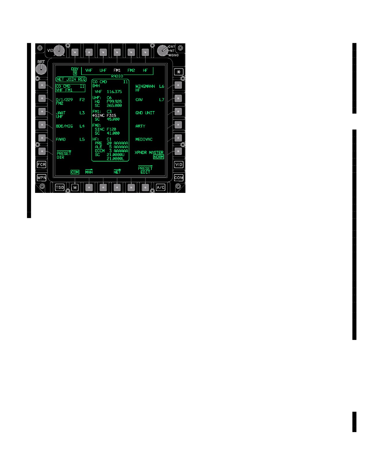
3A.24.3 NET JOIN REQ Status Window. The NET
JOIN REQuired status window, displayed in white, (fig
3A-9) is commonly displayed for several seconds follow-
ing a FS or TI FM1/FM2 radio tune when the IDM is
expecting a different radio configuration then what the
radio has reported. An automatic NET JOIN to SINC the
IDM with the selected FM radio is performed each time
that a FS or TI preset - net is tuned to FM1/FM2. Digital
messages cannot be transmitted over the tuned TI or FS
preset - net until the advisory is no longer displayed.
NOTE
• When a EUFD IDM FAULT is reporting a
TI FM1 NO RESPONSE, TI FM2 NO RE-
SPONSE, FS FM1 NO RESPONSE, or
FS FM2 NO RESPONSE, the system has
lost the ability to detect a mismatch con-
dition and will not issue a NET JOIN sta-
tus window.
• In the case that the NET JOIN REQ sta-
tus window remains displayed following a
LBA5084B
TI tune, the operator should ensure that
the pertinent FM radio’s HOPSET num-
Figure 3A-9. NET JOIN REQ Status Window
ber (###) matches the TI UTO’s NET ID
number (###) and then retune the radio.
3A.24.4 TI SEEK Status Window. The TI SEEK status
3A.24.1 IDM IN STANDBY Status Window. The IDM
window is displayed when either FM1 or FM2 has been
IN STANDBY status window is displayed whenever the
tuned to the Tactical Internet and the IDM has not estab-
IDM is in the standby mode. This status window is
lished a connection to a TI EPLRS - network gateway. This
displayed in white. No digital messages can be
status window, fig 3A-8, is displayed in inverse green. The
transmitted or received until the IDM is placed in the
IDM will continuously transmit until the gateway sends a
operational mode.
system message to the IDM that the TI EPLRS network
has been established. Once established, the TI status
3A.24.2 IDM INHIBIT Status Window. The IDM INHI-
window will extinguish and a EUFD TI Gateway Con-
BIT status window is displayed whenever the IDM SET
nected indicator symbol will display; see paragraph
page INHBT button is selected. Digital messages cannot
3A.16 - 12 and fig 3A-4.
be transmitted or received until the IDM is placed in the
operational mode. This status window is displayed in
3A.24.5 TI FOUND Status Window. The TI FOUND
white and an associated EUFD IDM INHIBIT advisory is
status window is displayed when either FM1 or FM2 has
displayed. See paragraph 3A.26.9.
been tuned to the Tactical Internet and the IDM has estab-
lished a connection to a TI EPLRS - network gateway.
NOTE
3A.24.6 TI LOGIN REQUIRED Status Window. The TI
LOGIN REQUIRED status window is displayed when the
When the IDM INHBT button is selected, L,
preset selected is for the TI protocol, and a valid user-
T, TI and FS command and control
name and password to verify TI has not been entered.
messages are still received. However, FS
Any FM1/FM2 TI preset tune performed without a LOGIN
artillery messages cannot be received,
will mode the preset - net to voice and will tune radio set-
since the IDM is required to transmit ACK
tings. LOGIN of a valid username and password is accom-
back to the sending platform in order to
plished through the DTU page NAME PASSWORD butt-
receive the message. TI messages will be
ton (paragraph 2.129.3B).
received unless the size of the message is
too large (>576 byte packet) or the length of
3A.24.7 URN NOT IN UTO Status Window. The URN
time since the last automatic present
NOT IN UTO status window is displayed to show that the
position report has timed out.
ownship URN is not in the current UTO when a TI radio
Use or disclosure of this information is subject to the restriction(s) on the title page of this document.
Change 4
3A-21
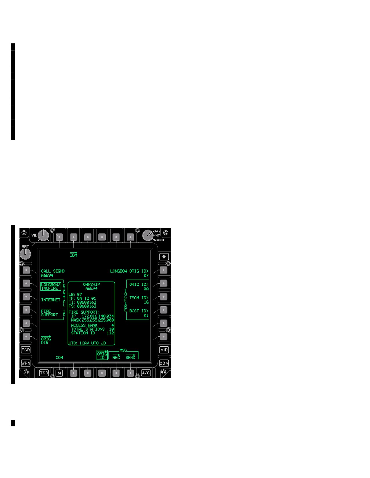
TM 1-1520-251-10
tune is executed. This indicates either an incorrect UTO or
• L2
DIGITAL ID LONGBOW/TACFIRE but
an incorrect URN. Accordingly, the operator may attempt
ton
to correct this by changing to another UTO that contains
• L3
DIGITAL ID INTERNET button
the ownship URN from the IDM page UTO button, or by
• L4
DIGITAL FIRE SUPPORT button
correcting the ownship URN from the ORIG ID page TI
• L6
ORIG DIR button
URN ID or FS URN ID button.
• R1
LONGBOW ORIG ID button
3A.24.8 TI UTO UPDATE REQ Status Window. The TI
• R2
TACFIRE ORIG ID button
UTO UPDATE REQ status window is displayed when a
• R3
TACFIRE TEAM ID button
UTR (Unit Task Reorganization) has been issued, making
• R4
TACFIRE BCST ID button
changes to the UTO. The operator may continue using the
• B4
ORIG ID button
current UTO or may select another UTO from the IDM
page UTO button, but should update the affected UTO da-
• B5
MSG REC button
tabase when they return to the FARP.
• B6
MSG SEND button
3A.25 ORIG ID PAGE Button. The ORIG ID page (fig
3A.25.1 CALL SIGN Button. The originator’s CALL
3A-10) is accessed by selecting the ORIG ID page
SIGN data entry button permits editing, and creation of,
button located on the COM page. The ORIG ID page
the originator’s call sign as displayed in the OWNSHIP
provides a means of editing the originator/ownship’s
Status window.
callsign and digital identification for the the L, T, TI, and
3A.25.2 DIGITAL ID LONGBOW/TACFIRE But-
FS IDM protocols and Quick Fire Net parameters. Upon
ton. The LONGBOW/TACFIRE button selections per-
display of the page, the DIGITAL ID
LONGBOW/TACFIRE button is selected. The ORIG ID
mits the editing, and creation, of LONGBOW ORIG ID,
page also contains the SET page button (paragraph
TACFIRE ORIG ID, ORIG BCST ID, and ORIG TEAM ID
3A.26).
page.
3A.25.2A ORIG DIR Button. The ORIG DIR button
supports the selection and editing/creation of ORIG global
data for current and future digital protocols. The ORIG
DIR uses the MBR DIR data base items.
3A.25.3 LONGBOW ORIG ID Button. The LONG-
BOW ORIG ID data entry button permits editing the IDM
Originator ID for the Longbow protocol. This ID is used as
the sender’s ID when transmitting Longbow messages.
The keyboard label displays LONGBOW ID and accepts a
one or two - character input between 0 - 39, A - Z, 1A - 1Z,
2A - 2Z, or 3A - 3I.
3A.25.4 TACFIRE ORIG ID Button. The TACFIRE
ORIG ID data entry button permits editing the IDM origina-
tor ID for the Tacfire protocol. This ID is used as the send-
er’s ID when transmitting Tacfire messages. The key-
board label displays TACFIRE ID and accepts a one or
two character input between 0 - 39, A - Z, 1A - 1Z, 2A - 2Z,
or 3A - 3I.
NOTE
LBA5478
The TACFIRE TEAM ID has to initially be
entered as a member in at least one TAC-
Figure
3A-10.
ORIG ID Page LONGBOW/TACFIRE
FIRE preset-net prior to the TACFIRE
Buttons on the ORIG ID page, LONGBOW/TACFIRE se-
TEAM ID being entered through the ORIG
lected:
ID page.
• T2
IDM button
3A.25.5 TACFIRE TEAM ID Button. The TACFIRE
• L1
CALL SIGN button
TEAM ID data entry button permits editing the originator’s
Use or disclosure of this information is subject to the restriction(s) on the title page of this document.
3A-22
Change 4
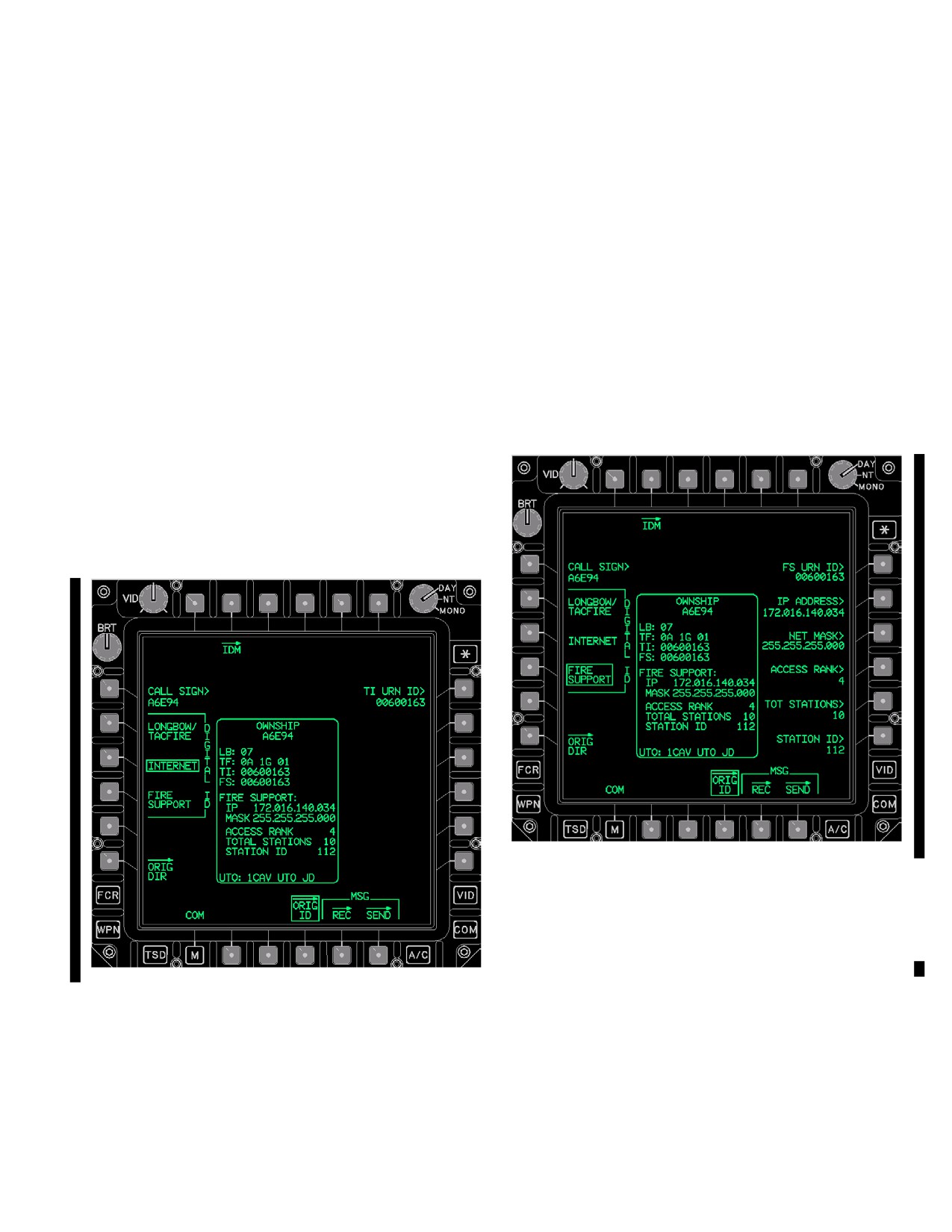
TM 1-1520-251-10
Tacfire Team ID. This ID represents the TACFIRE team
• R1
TI URN ID button
address associated with ownship’s IDM. The keyboard la-
NOTE
bel displays TEAM ID and accepts a one or two character
input between 0 - 39, A - Z, 1A - 1Z, 2A - 2Z, or 3A - 3I.
Editing the TI URN ID button will also edit
the FS URN ID: the 304 5.1x IDM only sup-
NOTE
ports a single URN for both protocols
The TACFIRE BCST ID has to initially be
3A.25.8 TI URN ID Button. The originator’s INTER-
entered as a member in at least one TAC-
NET TI URN ID data entry button permits editing the cur-
FIRE preset-net prior to the TACFIRE
rent tactical internet digital URN ID. The keyboard label
BCST ID being entered through the ORIG
displays TI URN and accepts a data entry of 0 through
ID page.
16,777,215.
3A.25.6 TACFIRE BCST ID Button. The TACFIRE
BCST ID data entry button permits editing the IDM’s
3A.25.9 DIGITAL ID FIRE SUPPORT Button. The
Broadcast ID for the Tacfire protocol. This ID represents
originators DIGITAL ID FIRE SUPPORT button (fig
the TACFIRE broadcast address associated with the origi-
3A-12) selection commands the display of Fire Support
nator’s aircraft. The keyboard label displays BROAD-
originator ID data.
CAST ID and accepts a one or two character input be-
tween 0 - 39, A - Z, 1A - 1Z, 2A - 2Z, or 3A - 3I.
3A.25.7 DIGITAL ID INTERNET Button. The origina-
tor’s DIGITAL ID INTERNET button (fig 3A-11) selection
commands the display of Tactical interface originator ID
data.
LBA5480
Figure 3A-12. ORIG ID Page FIRE SUPPORT
Buttons on the ORIG ID page, FIRE SUPPORT selected:
• T2
IDM button
LBA5479
• L1
CALL SIGN button
Figure 3A-11. ORIG ID Page INTERNET
• L2
DIGITAL ID LONGBOW/TACFIRE but
ton
Unique buttons on the ORIG ID page, INTERNET se-
• L3
DIGITAL ID INTERNET button
lected:
• L4
DIGITAL FIRE SUPPORT button
• L3
DIGITAL ID INTERNET button
• R1
FS URN ID button
Use or disclosure of this information is subject to the restriction(s) on the title page of this document.
Change 4
3A-23
TM 1-1520-251-10
• R2
IP ADDRESS button
fire net access rank. The keyboard label displays AC-
CESS RANK and accepts a data entry of 0 through 127.
• R3
NET MASK button
• R4
ACCESS RANK button
3A.25.14 TOT STATIONS Button. The originator’s
• R5
TOT STATIONS button
FIRE SUPPORT TOT STATIONS data entry button per-
mits editing the quick fire net’s total number of fire support
• R6
STATION ID button
stations. The keyboard label displays TOT STAT and ac-
• B4
ORIG ID button
cepts a data entry of 0 through 127.
• B5
MSG REC button
3A.25.15 STATION ID Button. The originator’s FIRE
• B6
MSG SEND button
SUPPORT STATION ID data entry button permits editing
the fire support quick fire net station ID. The keyboard la-
3A.25.10 FS URN ID Button. The originator’s Fire
bel displays STATION ID and accepts a data entry of 4
Support Unit Reference Number data entry button per-
through 127.
mits editing, and creation of, the originator’s FS URN ID.
The keyboard label displays FS URN and accepts a data
3A.26 IDM PAGE
entry of 0 through 16,777,215.
The IDM page is accessed by selecting the IDM page but-
NOTE
ton from either the COM page, ORIG ID page, or the MSG
SEND page. The IDM page provides a means of editing
• The existing FIRE SUPPORT network re-
various IDM parameters for both the Tactical Internet and
quires a unique IP association with each
Fire Support. It also provides access to changing the
entity’s digital ID URN.
IDM’s mode (standby or operate) and to inhibit the IDM
• Editing the FS URN ID button will also
from sending messages.
edit the TI URN ID: the 304 v7.x IDM only
supports a single URN for both protocols.
3A.25.11 IP ADDRESS Button. The originator’s FIRE
SUPPORT IP ADDRESS data entry button permits edit-
ing the current fire support IP address. The keyboard label
displays IP ADDR and accepts a data entry of 0.0.0.0
through 255.255.255.255.
3A.25.12 NET MASK Button. The ORIG ID page FIRE
SUPPORT NET MASK data entry button displays, and al-
lows modification of, the current fire support net mask.
The keyboard label displays NET MASK and accepts a
data entry of 0.0.0.0 through 255.255.255.255.
NOTE
• When required by the artillery, a NET
mask is used to create subnets and to de-
termine what subnet an IP address be-
longs to.
• The advantage of a subnet is that JVMF
LBA5481
traffic on the same subnet doesn’t have
to go out onto the network above it, re-
Figure 3A-13.
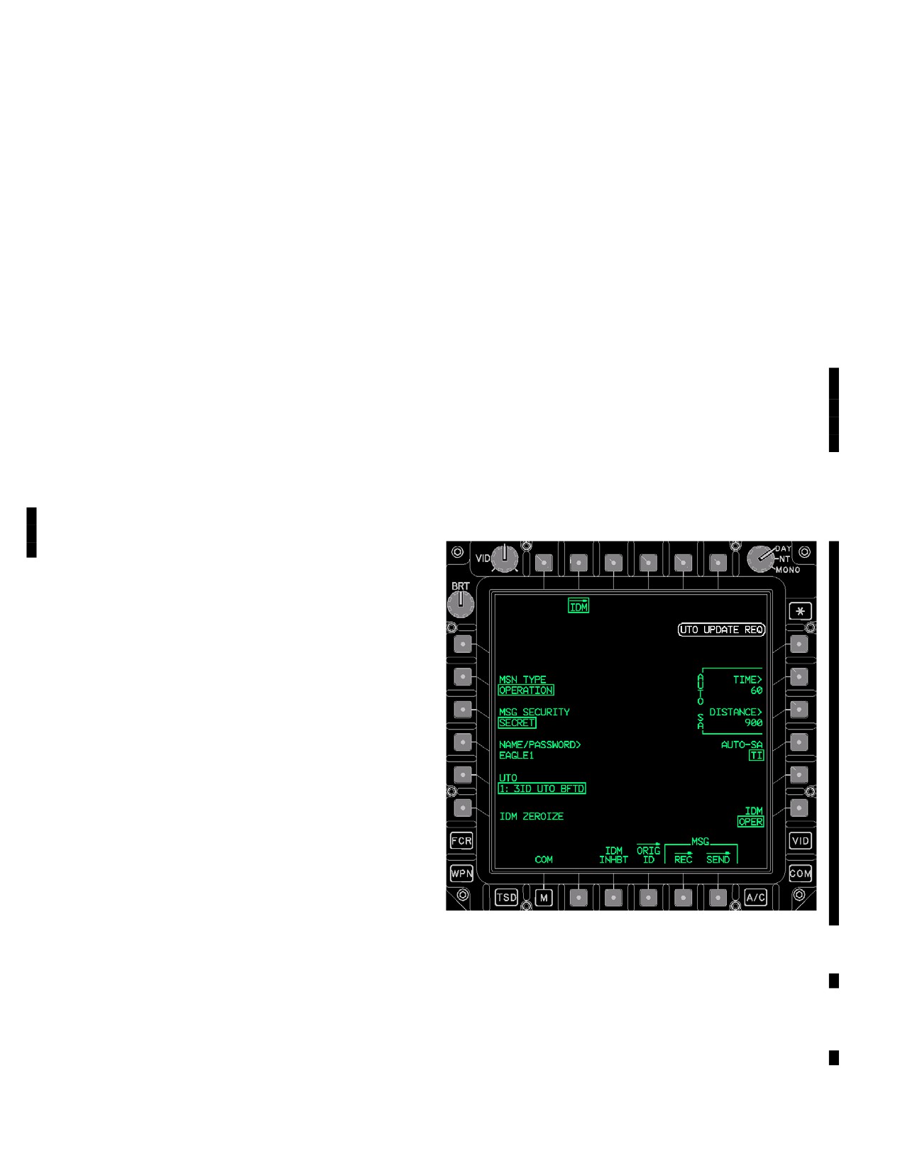
IDM SET Page
ducing the traffic bandwidth on the larger
Buttons on the SET page:
network.
• L2
MISSION TYPE button
3A.25.13 ACCESS RANK Button. The originator’s
• L3
MSG SECURITY button
FIRE SUPPORT ACCESS RANK data entry button per-
mits editing, and creation of, the current fire support quick
• L4
NAME/PASSWORD button
Use or disclosure of this information is subject to the restriction(s) on the title page of this document.
3A-24
Change 4
TM 1-1520-251-10
• L5
UTO button
• L6
IDM ZEROIZE button
• R2
IAUTO SA button
• R3
AUTO SA DUSTANCE button
• R4
AUTO SA button
• R6
IDM OPER/STBY button
• R3
IDM INHIBIT button
3A.26.1 MSN TYPE Button. The IDM page MSN TYPE
button provides the means to change the operational indica-
tor of the messages transmitted on the Tactical Internet or
Fire Support Nets. Selecting the MSN TYPE button provides
three options: OPERATION, EXERCISE, and SIMULATION.
3A.26.2 MSG SECURITY Button. The IDM page MSG
LBA5482
SECURITY button provides a means to change the secu-
rity level of the messages transmitted over the Tactical In-
Figure
3A-13A. UTO EDIT OPTIONS
ternet or Fire Support Nets. Selecting the MSG SECURI-
TY button provides three options: SECRET,
NOTE
CONFIDENTIAL, and UNCLASSIFIED.
Member data is retained in DP NVM and is not
reset, with the exception of IDM messages,
the remaining data can subsequently be re-
NOTE
loaded via the DTC.
3A.26.4 IDM ZEROIZE Button. The IDM ZEROIZE
• The IDM will not accept incoming TI and FS
button provides a yes/no confirmation for resetting the
messages that are set to a security classifi-
following data in the IDM:
cation level that is higher than the current
login security level setting.
• Originator data (for tactical internet information)
• Subscriber data
• The resident IDM UTO’s are received from
• Teams
the loaded DMS DTU page.
• Nets
• Zones
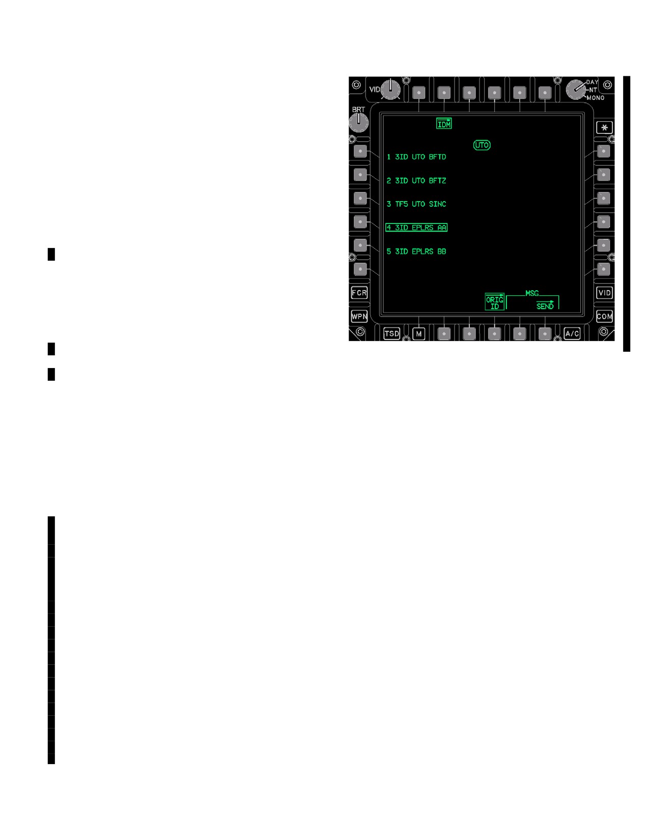
3A.26.3 UTO Button. The IDM page UTO button provides
• Messages (that reside in the message receive
a means to select / change the single UTO that the IDM will
buffer)
utilize. The UTO button displays the UTO number and name
3A.26.5 AUTO SA TIME Button. The ORIG ID/MSG
descriptor. Selecting the UTO button will display up to 5 differ-
SEND IDM SET page AUTO SA TIME data entry button al-
ent UTO edit button options (figure 3A-13A), each one asso-
lows the operator to set the maximum time interval for the
ciated with a display field number of 1-5. All the numbered
IDM to transmit the TI Entity Data Message message (provid-
UTO edit button display fields include a unique UTO name
ing the present position information) to the Tactical Internet
descriptor of up to 12 characters. Selecting a numbered UTO
SA server. The IDM will only send this message when tuned
edit button will: 1) command the IDM to use the selected
to the TI and the SA ON/OFF button is ON. The valid data
UTO; 2) command the IDM page to be displayed; 3) display
entry is 11 through 4095 seconds.
the UTO’s asscociated number of 1-5 with the UTO button; 4)
will display the TI UTO status window with the active UTO’s
3A.26.6 AUTO SA DISTANCE Button. The ORIG ID/
unique name descriptor (paragraph 3A.26.11).
MSG SEND IDM SET page AUTO SA DISTANCE data
Use or disclosure of this information is subject to the restriction(s) on the title page of this document.
Change 4
3A-25
TM 1-1520-251-10
entry button allows the operator to set the maximum change
Unit Task Organization (UTO) that the IDM is currently config-
in distance before the IDM sends the TI Entity Data Message
ured with. This status window is only displayed when the IDM
message (providing the present position information) to the
is in operate.
Tactical Internet SA server. The IDM will only send this mes-
3A.27 COM PAGE - PRESET SELECTED
sage when tuned to the TI and the SA ON/OFF button is ON.
The valid data entry is 10 - 2000 meters.
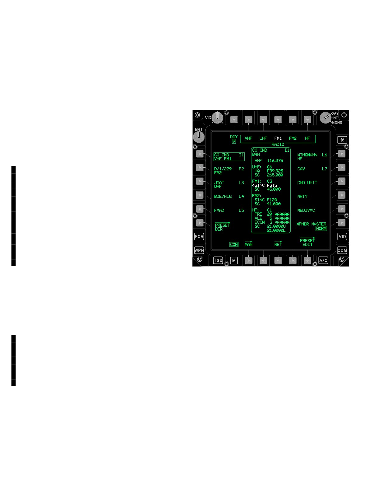
The COM page (fig 3A-14) preset status window displays
the data associated with the preset that is currently se-
3A.26.7 AUTO-SA Button. The AUTO SA button allows
lected.
the operator to either enable JVMF position reports to be au-
tomatically issued over TI, or to DISABLE the IDM’s capability
to automatically report the TI Entity Data Message message
(providing the present position information) to the Tactical In-
ternet SA server. The message will be transmitted when the
time set by the AUTO SA TIME has elapsed or the aircraft
has moved (from the last position reported) farther than the
distance set by the AUTO SA DISTANCE.
3A.26.8 IDM OPER/STBY Button. The IDM page’s IDM
OPER/STBY button permits the operator to toggle between
standby and operate. Whenever the IDM is in STBY, digital
messages cannot be transmitted and JVMF messages will
not be received. The IDM must be set to STBY before re-
moving aircraft power or prior to the need to reset the IDM
circuit breaker. When in STBY, an IDM IN STANDBY adviso-
ry will be displayed on the COM page and EUFD.
NOTE
Any SA data or JVMF messages already re-
ceived will be lost when the IDM transitions
to STBY.
LBA5089
3A.26.9 IDM INHBT Button. When selected, the IDM SET
page IDM INHBT button prevents the IDM from performing
Figure 3A-14. COM Page (PRESET Selected)
automatic message transmits on any IDM tuned radio (in-
cluding machine ACKs for all protocols and automated re-
The following unique buttons are displayed on the COM
sponse messages). The selected IDM INHBT button is white
page when a preset is selected:
and the send buttons will be removed from all pages. When
• T2
RADIO VHF button
selected, an IDM INHIBIT advisory will be displayed on the
COM page and EUFD.
• T3
RADIO UHF button
• T4
RADIO FM1 button
• The IDM INHBT button does not inhibit
HF radio transmissions.
• T5
RADIO FM2 button
• T6
RADIO HF button
• The HF radio’s transmissions are inhib-
• B4
NET page button
ited when the HF is moded to SILENT or,
when on the ground, the HF GND ORIDE
• B6
PRESET EDIT page button
button is not selected (unboxed).
NOTE
Each specific RADIO T2-T6 buttons are
3A.26.10 IDM MISMATCH STATUS Window. The IDM
displayed anytime the selected preset con-
MISMATCH STATUS window displays the mismatch status
tains valid data for the radio type.
for TI IDM parameters. This status window is only displayed
when TI is tuned to one of the radios and the IDM is reporting
3A.27.1 NET Page Button. The NET button displays
one of the parameters is different from what was commanded
the net member page. See paragraph 3A.33.
by the DP.
3A.27.2 PRESET EDIT Page Button. The PRESET
3A.26.11 UTO STATUS Window. The ORIG ID/MSG
EDIT button displays the preset edit page. See paragraph
SEND IDM SET page UTO STATUS window displays the
3A-17.
Use or disclosure of this information is subject to the restriction(s) on the title page of this document.
3A-26
Change 4
TM 1-1520-251-10
3A.27.3 COM PRESET Status Window. The COM
• HF ALE
PRESET status window data is displayed in the following
• HF ECCM
field order:
• HF SC (Upper/Lower)
• Unit ID
• Call Sign
The Primary frequency is displayed in white and desig-
• DM Type and IDM Preset - Net Number
nated by a white arrow.
• VHF Frequency
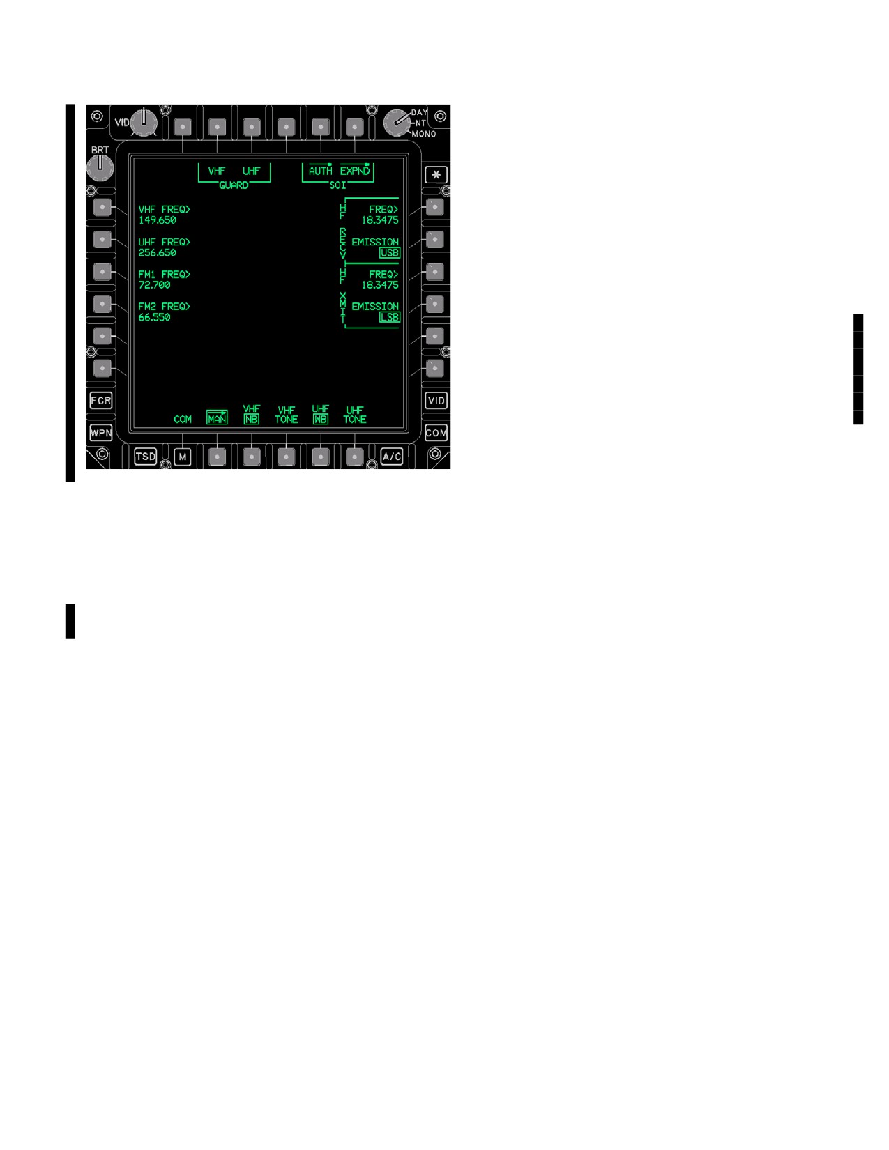
3A.28 MAN PAGE
• UHF CNV status
• UHF HQ Net number
The MAN page (fig 3A-15) provides the capabilities:
• UHF Single Channel Frequency
• Tune the VHF and/or UHF guard frequency.
• FM1 CNV status
• Manually tune the VHF, UHF, FM1, FM2, and HF
• FM1 SINC net number
radios through frequency data input.
• FM1 Single Channel Frequency
• FM2 CNV status
• Select antenna bandwidths for the UHF and VHF
radios.
• FM2 SINC HOPSET number
• FM2 CNV status
• UHF/VHF radio test tone button access.
• HF CNV status
• Provides access to the SOI AUTH and SOI
• HF PRE
EXPND pages
Use or disclosure of this information is subject to the restriction(s) on the title page of this document.
Change 4
3A-26.1/(3A-26.2 blank)
TM 1-1520-251-10
VHF radio (108.000 through 151.975 MHz at 0.025 spac-
ing) using the KU. The KU label display is VHF FREQ and
the selection of the KU’s ENTER button commands the
VHF radio to tune to the manually set frequency.
3A.28.4 UHF FREQ Button. The UHF FREQ data
entry button provides the capability to manually tune the
UHF radio (225.000 through 399.975 MHz at 0.025 spac-
ing steps) using the KU. The KU label display is UHF
FREQ and the selection of the KU’s ENTER button com-
mands the UHF radio to tune to the manually set frequen-
cy.
3A.28.4A SOI AUTH Page Button. The SOI AUTH
page button provides the capability to authenticate com-
munication transmissions and access expanders.
3A.28.4B SOI EXPND Page Button. The SOI EXPND
page (fig 3A-15F) provides the capability to view the ex-
pander lookup table.
3A.28.5 FM1 FREQ Button. The FM1 FREQ data
entry button provides the capability to manually tune the
LBA5483
FM1 radio (30.000 through 87.975MHz at 0.025 MHz
steps) using the KU. The KU label display is FM1 FREQ
Figure 3A-15. MAN Page
and the selection of the KU’s ENTER button commands
the FM1 radio to tune to the manually set frequency.
The MAN page contains the following unique buttons:
3A.28.6 FM2 FREQ Button. The FM2 FREQ data
• T2
VHF GUARD button
entry button provides the capability to manually tune the
• T3
UHF GUARD button
FM1 radio (30.000 through 87.975MHz at 0.025 MHz
• T5
SOI AUTH page button
steps) using the KU. The KU label display is FM2 FREQ
and the selection of the KU’s ENTER button commands
• T6
SOI EXPND button
the FM2 radio to tune to the manually set frequency.
• L1
VHF FREQ button
• L2
UHF FREQ button
3A.28.7 HF RECV FREQ Button. The HF RECV
FREQ data entry button provides the capability to manual-
• L3
FM1 FREQ button
ly tune the HF radio receive frequency (2.0000 through
• L4
FM2 FREQ button
29.9999 MHZ at 0.1 kHz steps). The KU label display is
• R1
HF RECV FREQ button
HF RECV FREQ and the selection of the KU’s ENTER
• R2
HF RECV EMISSION (USB/LSB) button
button commands the HF radio to tune to the manually set
• R3
HF XMIT FREQ button
HF RECV frequency.
• R4
HF XMIT EMISSION (USB/LSB) button
3A.28.8 HF RECV EMISSION Button. The HF RECV
• B3
VHF WB/NB antenna button
EMISSION button provides the capability to select the HF
• B4
VHF TONE button
radio receive emission mode for the manual receive fre-
• B5
UHF WB/NB antenna button
quency. The button provides the following HF RECV
• B5
UHF TONE button
EMISSION multi - state options:
• AME to select Amplitude Modulation Equivalent.
3A.28.1 VHF GUARD Button. The VHF GUARD but-
ton provides the capability to rapidly tune the VHF radio to
• CW to select Continuous Wave.
the guard frequency.
• LSB to select Lower Sideband.
3A.28.2 UHF GUARD Button. The UHF GUARD but-
• USB to select Upper Sideband.
ton provides the capability to rapidly tune the UHF radio to
Upper Sideband is the default receive emission mode
the guard frequency.
upon power - up. Changing the receive emission mode of
3A.28.3 VHF FREQ Button. The VHF FREQ data
the HF radio automatically changes the transmit emission
entry button provides the capability to manually tune the
mode to the same value.
Use or disclosure of this information is subject to the restriction(s) on the title page of this document.
Change 4
3A-27
TM 1-1520-251-10
3A.28.9 HF XMIT FREQ Button. The HF XMIT FREQ
3A.28.14 UHF TONE Button. The UHF TONE momen-
data entry button provides the capability to manually tune
tary button provides the capability to enable the UHF Ra-
the HF radio receive frequency (2.0000 through 29.9999
dio (ARC - 164) Test Tone. Selection of the UHF TONE
MHZ at 0.1 kHz steps). The KU label display is HF XMIT
button transmits an over the air radio generated tone. The
FREQ and the selection of the KU’s ENTER button com-
tone is used for test and problem isolation.
mands the HF radio to tune to the manually set HF XMIT
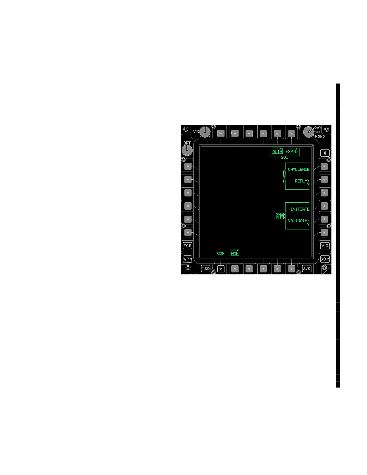
3A.28A MAN SOI AUTH Page
frequency.
The AUTH page (fig 3A-15A) provides the capability to
3A.28.10 HF XMIT EMISSION Button. The HF XMIT
authenticate communication transmissions and access
EMISSION button provides the capability to select the HF
expanders.
radio receive emission mode for the manual receive fre-
quency. The button provides the following HF XMIT EMIS-
SION multi - state options:
• AME to select Amplitude Modulation Equivalent.
• CW to select Continuous Wave.
• LSB to select Lower Sideband.
• USB to select Upper Sideband.
Upper Sideband is the default receive emission mode
upon power - up. Changing the receive emission mode of
the HF radio automatically changes the transmit emission
mode to the same value.
3A.28.11 VHF WB/NB Button. VHF WB/NB button
provides the capability to toggle between the WB (Wide
Bandwidth, 18KHz) and NB (Narrow Bandwidth, 9.5KHz)
modes. The default state upon power-up for the VHF
bandwidth is narrow.
3A.28.12 VHF TONE Button. The VHF TONE momen-
tary button provides the capability to enable the VHF Ra-
dio (ARC - 186) Test Tone. Selection of the VHF TONE
LBA5119
button transmits an over the air radio generated tone. The
tone is used for test and problem isolation.
Figure
3A-15A.
MAN SOI AUTH Page
3A.28.13 UHF WB/NB Button. UHF WB/NB button
• T5
AUTH (Authentication) page button
provides the capability to toggle between the WB (Wide
• T6
EXPND (Expander) page button
Bandwidth, ±35KHz deviation from the channel frequency
• R1
AUTH CHALLENGE button
allowing more noise or crosstalk from frequencies within
.025MHz ) and NB (Narrow Bandwidth allows ±12KHz
• R2
AUTH REPLY button
deviation from the channel frequency) modes. The default
• R4
XMSN AUTH INITIATE button
state upon power - up for the VHF bandwidth is narrow.
• R5
XMSN AUTH VALIDATE button
The UHF bandwidth is automatically set to WB option
when the UHF mode is set to the UHF CIPHER and to NB
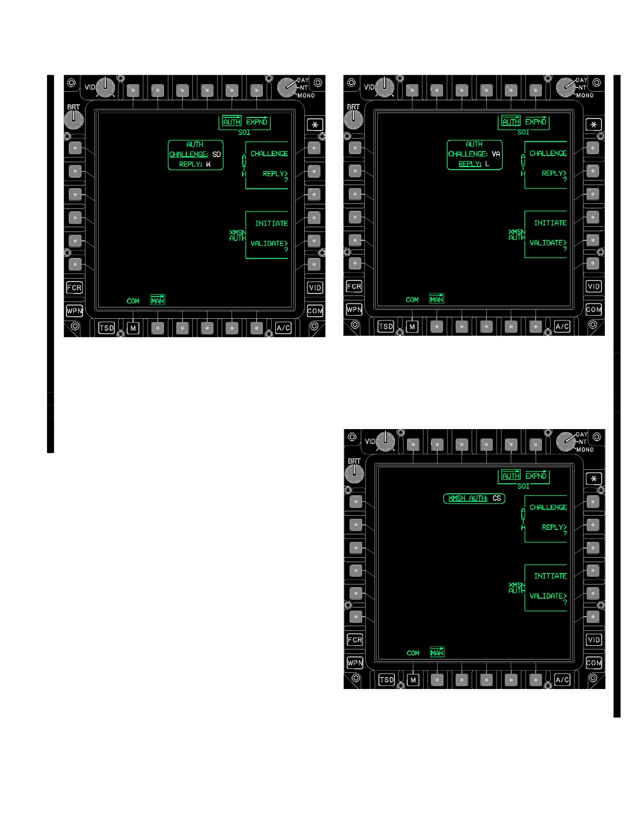
3A.28A.1 AUTH CHALLENGE Button. The AUTH
when the UHF mode is set to the UHF PLAIN. Upon pow-
CHALLENGE button provides the capability to extract the
er - up, the UHF bandwidth is determined by the state of
challenge/reply table and display the codes within the
the UHF KY - 58.
AUTH CHALLENGE REPLY window (fig 3A-15B ).
Use or disclosure of this information is subject to the restriction(s) on the title page of this document.
3A-28
Change 4
TM 1-1520-251-10
LBA5485
LBA5486
Figure 3A-15C. AUTH Page - AUTH REPLY
Figure 3A-15B. AUTH Page - AUTH CHALLENGE
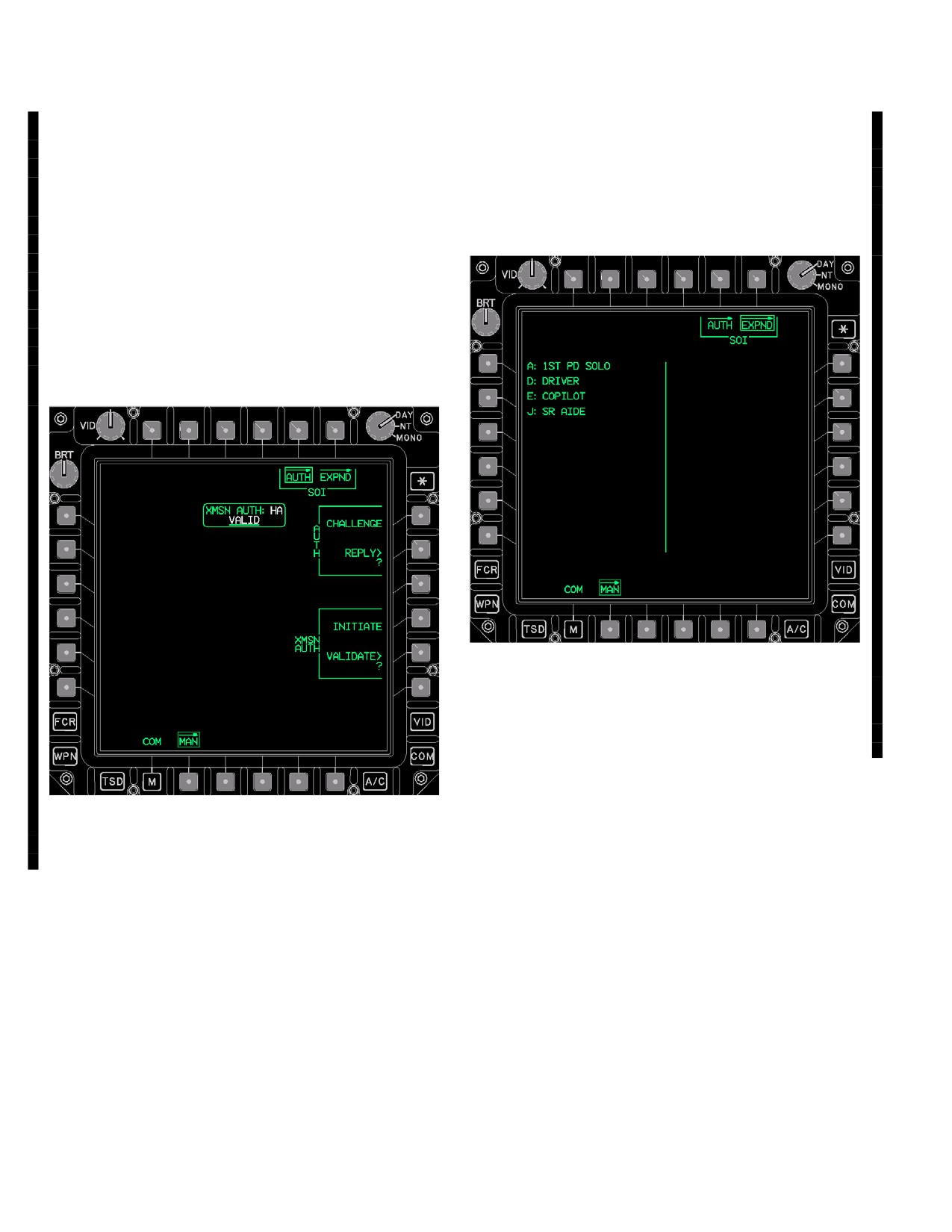
3A.28A.3 XMSN AUTH INITIATE Button. The XMSN
AUTH INITIATE button extracts the transmit authentica-
3A.28A.2 AUTH REPLY Button. The AUTH REPLY
tion codes and displays them in the XMSN AUTH window
button provides the capability to enter a challenge code
(fig 3A-15D).
and extract the reply code from the challenge/reply table
and display the code within the AUTH CHALLENGE RE-
PLY window (fig 3A-15C).
LBA5487
Figure 3A-15D. AUTH Page - XMSN AUTH INITIATE
Use or disclosure of this information is subject to the restriction(s) on the title page of this document.
Change 4
3A-28.1
TM 1-1520-251-10
NOTE
3A.28A.5 EXPANDER (EXPND) PAGE
An ALL CODES USED message will be dis-
The EXPND page (fig 3A-15F), a view - only page, pro-
played in white when all the codes have
vides the capability to view the expander lookup table.
been used.
The expander lookup table displays the one character ex-
pander and descriptor field. Up to 26 expanders may be
3A.28A.4 XMSN AUTH VALIDATE Button. The
displayed from the lookup table.
XMSN AUTH VALIDATE button (fig 3A-15E) provides the
capability to verify a transmit authentication code from the
transmit authentication table. The VALID label is dis-
played when the transmit authentication matches the
transmit authentication code entered through the KU. The
INVALID label is displayed when the transmit authentica-
tion table does not match the transmit authentication code
entered through the KU.
LBA5490
Figure 3A-15F. MAN SOI EXPND Page
3A.28A.6 EXPND Page Button. The EXPND button dis-
plays the EXPND page (para 3A.23).
3A.29 COM PAGE - PRESET AND RADIO SELECTED
LBA5489
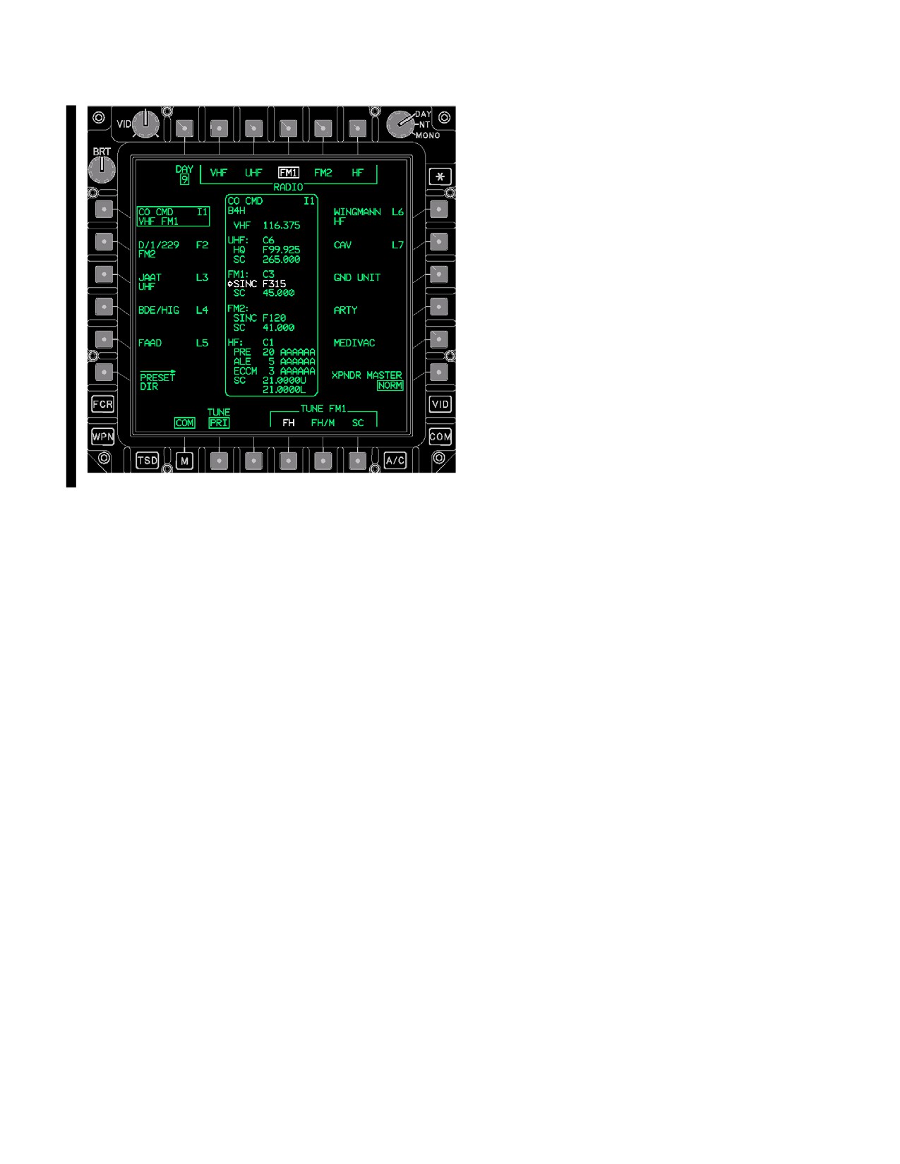
The COM page (fig 3A-16) specific TUNE VHF, FM1,
Figure 3A-15E. AUTH Page - XMSN AUTH
FM2, or HF button options are displayed following the
VALIDATE
selection of a RADIO option button.
Use or disclosure of this information is subject to the restriction(s) on the title page of this document.
3A-28.2
Change 4
TM 1-1520-251-10
The COM page with preset selected contains the follow-
ing unique buttons:
• T2
RADIO VHF button
• T3
RADIO UHF button
• T4
RADIO FM1 button
• T5
RADIO FM2 button
• T6
RADIO HF button
a. TUNE RADIO Command IDM - RADIO Configu-
ration Updates. When a VHF, UHF, FM1, or FM2 TUNE
RADIO button assigned to an IDM preset - net is selected
the following radio and IDM processes occur:
• The radio will tune - configure.
• The radio channel in the IDM will be configured
LBA5091A
when the preset has an IDM protocol assigned.
Figure
3A-16.
COM Page Preset and Radio FM1
• The Crypto in the KY will be configured if the preset
Selected
has a Crypto Net Variable displayed.
Use or disclosure of this information is subject to the restriction(s) on the title page of this document.
Change 4
3A-28.3/(3A-28.4 blank)
TM 1-1520-251-10
NOTE
3A.29.3 PRESET RADIO FM1 or FM2 Button. The
selection of the PRESET RADIO FM1 or FM2 button will
TI and FS preset - nets require the exclusive
command the display of the TUNE FM1 or FM2 button op-
use of either FM1 or FM2. A TI or FS preset
tions.
NET tuned to a UHF, VHF, or HF radio will
change the preset - net to voice only.
• B4
TUNE FM1 or FM2 FH button
• B5
TUNE FM1 or FM2 FH/M button
b. TUNE RADIO Command EUFD Radio Status
• B6
TUNE FM1 or FM2 SC button
Line Update. When any one of the TUNE RADIO option
buttons is selected, the EUFD’s preexisting primary radio
a. TUNE FM1 or FM2 FH Button. Selecting the
status line is moved to the EUFD’s standby area and the
TUNE FM1 or FM2 FH button tunes the specific FM radio
EUFD primary status is updated with the applicable PRE-
to the SINC FH using the NET ID displayed in the FM1 or
SET STATUS windows:
FM2 SINC status field of the PRESET STATUS window.
• Call Sign.
b. TUNE FM1 or FM2 FH/M Button. Selecting the
TUNE FM1 or FM2 FHM button tunes the specific FM ra-
• Frequency.
dio to the SINC FH/M mode using the NET ID that is dis-
• Frequency - Hop/ECCM.
played in the FM1 or FM2 SINC status field of the PRE-
SET STATUS window. The FH/M tune makes the aircraft
• IDM Protocol.
the master of the SINCGARS NET.
• Crypto Status Fields.
c. TUNE FM1 or FM2 SC Button. Selecting the
TUNE FM1 or FM2 SC button tunes the specific FM radio
c. TUNE RADIO Command PRESET Button Up-
to the frequency displayed in the FM1 (or FM2) SC status
date. When any one of the TUNE RADIO option buttons
field of the PRESET STATUS window.
is selected, the radio tuned will be displayed in the second
line of the selected PRESET button.
3A.29.4 PRESET RADIO HF Button. The selection of
the PRESET RADIO HF button will command the display
3A.29.1 PRESET RADIO VHF Button. The selection
of the TUNE HF button options.
of the PRESET RADIO VHF button will command the dis-
• B3
TUNE HF PRE button
play of the TUNE VHF option button.
•
B4
TUNE HF ALE button
• B6
TUNE VHF SC button
• B5
TUNE HF ECCM button
Selecting the TUNE VHF SC button tunes the VHF radio
• B6
TUNE HF SC button
to the frequency displayed in the VHF SC status field of
NOTE
the PRESET STATUS window.
An IDM preset - net tuned to a HF RADIO
TUNE button option will change that preset -
3A.29.2 PRESET RADIO UHF Button. The selection
net to voice only.
of the PRESET RADIO UHF button will command the dis-
play of the TUNE UHF button options.
a. TUNE HF PRE Button. Selecting the TUNE HF
PRE button tunes the HF radio to preset 1 through 20 as
• B4
TUNE UHF FH button
displayed in the HF PRE status field of the PRESET STA-
• B6
TUNE UHF SC button
TUS window.
a. TUNE UHF FH Button. Selecting the TUNE UHF
b. TUNE HF ALE Button. Selecting the TUNE HF
FH button tunes the UHF radio to the HQ NET ID as dis-
ALE button tunes the HF radio to the HF ALE Channel (1
played in the UHF HQ status field of the PRESET STA-
through 5) that is displayed in the HF ALE Status Field of
TUS window.
the PRESET STATUS window.
b. TUNE UHF SC Button. Selecting the TUNE UHF
c. TUNE HF ECCM Button. Selecting the TUNE
SC button tunes the UHF radio to the frequency displayed
HF ECCM button tunes the HF radio to the HF ECCM Net
in the UHF SC status field of the PRESET STATUS win-
displayed in the HF ECCM Status Field of the PRESET
dow.
STATUS window.
Use or disclosure of this information is subject to the restriction(s) on the title page of this document.
Change 2
3A-29
TM 1-1520-251-10
d. TUNE HF SC Button. Selecting the TUNE HF
3A.30.2 EDIT UNIT ID Button. The EDIT UNIT ID but-
SC button tunes the HF radio to the HF SC frequencies for
ton changes the preset Unit ID.
both the upper (U) and lower (L) sidebands as displayed
in the HF SC Status Field of the PRESET STATUS win-
3A.30.3 EDIT CALL SIGN Button. The EDIT CALL
dow.
SIGN button changes the preset call sign.
3A.30 PRESET EDIT PAGE
3A.30.4 EDIT PRIMARY RADIO Button. The EDIT
PRIMARY RADIO button provides the capability to
change the radio-frequency/radio-mode association of
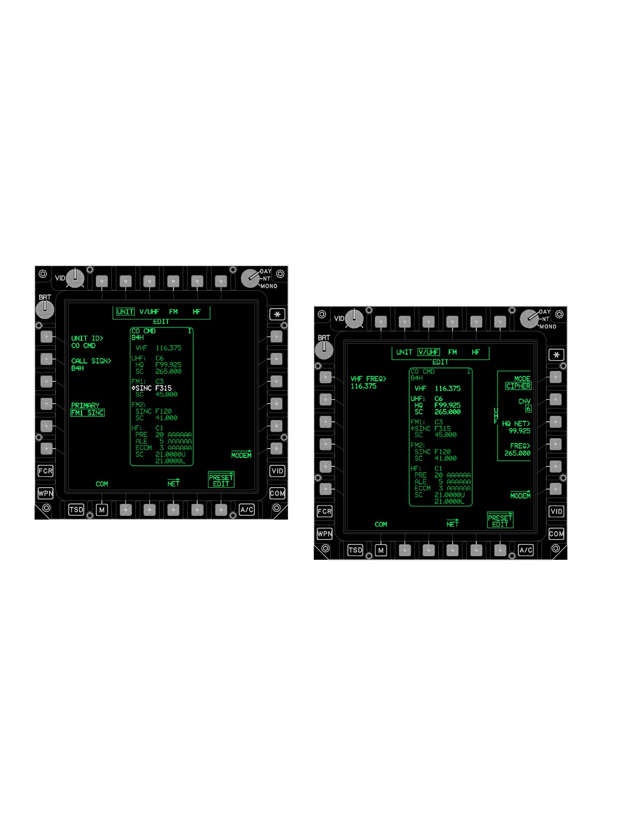
The PRESET EDIT page (fig 3A-17) provides the capabili-
the Primary Radio indicator arrow (i.e. non - solid arrow) in
ty to modify the currently selected preset as displayed in
the PRESET STATUS window.
the PRESET STATUS window. Along with the Unit ID,
those items currently displayed for edit are displayed in
3A.30.5 MODEM Page Button. The MODEM button
full intensity in the PRESET STATUS window, as opposed
displays the MODEM page. See paragraph 3A.31.
to partial intensity.
3A.30.6 PRESET EDIT Page Button. The PRESET
EDIT page button displays the PRESET EDIT page (fig
3A-18).
LBA5092
Figure 3A-17. PRESET EDIT Page (UNIT Selected)
LBA5093
The PRESET EDIT page contains the following unique
Figure 3A-18. PRESET EDIT Page (V/UHF Selected)
buttons when the EDIT grouped option is UNIT:
• T2 - T5
EDIT buttons
The PRESET EDIT page contains the following unique
buttons when the EDIT grouped option is V/UHF:
• L1
EDIT UNIT ID button
• L2
EDIT CALL SIGN button
• L1
EDIT VHF FREQ button
• L4
EDIT PRIMARY RADIO/MODE button
• R1
EDIT UHF MODE button
• R6
MODEM page button
• R2
UHF CNV selection button
• R3
EDIT HQ NET button
3A.30.1 EDIT Buttons. The EDIT buttons provide the
• R4
EDIT UHF FREQ button
capability to select a specific element of a preset’s COM
data to edit.
• R6
MODEM button
Use or disclosure of this information is subject to the restriction(s) on the title page of this document.
3A-30
Change 2
TM 1-1520-251-10
3A.30.7 EDIT VHF FREQ Button. The EDIT VHF
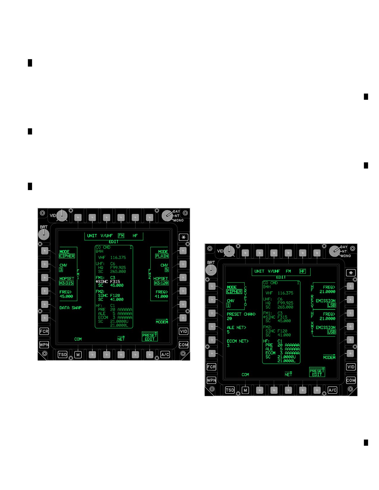
3A.30.12 EDIT FM1/FM2 MODE Button. The EDIT FM
FREQ button changes the VHF element of the preset to a
1/FM2 MODE button provides the capability to change the
frequency in the range of 108.000 through 155.995, in in-
UHF Crypto Mode by toggling between Plain or Cipher
crements of 5 KHz (except for invalid 8.33 KHz channels).
mode for the selected preset.
3A.30.8 EDIT UHF MODE Button. The EDIT UHF
3A.30.13 EDIT FM1/FM2 CNV Button. The EDIT
MODE button provides the capability to change the UHF
FM1/FM2 CNV button allows changing the Crypto Net
Crypto Mode by toggling between Plain or Cipher mode
Variable for the selected preset from 1-6.
for the selected preset.
3A.30.14 EDIT FM1/FM2 HOPSET Button. The HOP-
3A.30.9 EDIT UHF CNV Button. The EDIT UHF CNV
SET button provides six HOPSET button options. The
button allows changing the Crypto Net Variable, for the se-
hopset selected determines the radio FH characteristics
lected preset, from 1-6.
(hopping rate, frequencies and frequency order).
3A.30.10 EDIT HQ NET Button. The EDIT HQ NET
3A.30.15 EDIT FM1/FM2 FREQ Button. The EDIT
button changes the HAVEQUICK net number of the preset
FM1/FM2 FREQ button changes the FM1/FM2 for the se-
in the range of 00.000 to 99.975.
lected preset to a frequency in the range of 30.000
through 87.995, in increments of 5 KHz.
3A.30.11 EDIT UHF FREQ Button. The EDIT UHF
FREQ button changes the UHF element of the preset to a
3A.30.16 EDIT FM1/FM2 DATA SWAP Button. The
frequency in the range of 225.000 through 399.985 MHz
EDIT FM1/FM2 DATA SWAP button exchanges the FM1
in increments of 5 KHz.
and FM2 data displayed on the PRESET EDIT FM se-
lected page.
3A.30.17 EDIT HF CRYPTO MODE Button. The EDIT
HF CRYPTO MODE button (fig 3A-20) provides the capa-
bility to change the HF Crypto Mode by toggling between
Plain or Cipher mode for the selected preset.
LBA5094
Figure 3A-19. PRESET EDIT Page (FM Selected)
LBA5095
NOTE
Figure 3A-20. PRESET EDIT Page (HF Selected)
The PRESET EDIT FM selected page but-
tons (fig 3A-19) for FM1 and FM2 are func-
3A.30.18 EDIT HF CRYPTO CNV Button. The EDIT
tionally identical and the definitions below
HF CRYPTO CNV button allows changing the Crypto Net
apply to both radios.
Variable for the selected preset from 1-6.
Use or disclosure of this information is subject to the restriction(s) on the title page of this document.
Change 3
3A-31
TM 1-1520-251-10
3A.30.19 EDIT HF PRESET CHAN Button. The EDIT
HF PRESET CHAN button changes the HF Preset chan-
nel number of the preset in the range of 1-20.
3A.30.20 EDIT HF ALE NET Button. The EDIT HF
ALE NET button changes the HF ALE net number of the
preset in the range of 1-20.
3A.30.21 EDIT HF ECCM NET Button. The EDIT HF
ECCM NET button changes the HF ECCM net number of
the preset in the range of 1-12.
3A.30.22 EDIT HF RECV FREQ Button. The EDIT HF
RECV FREQ button changes the HF manual receive fre-
quency of the preset in the range of 2.0000 through
29.9999 MHz, in increments of 100 Hz.
3A.30.23 EDIT HF RECV EMISSION Button. The
LBA5096
EDIT HF RECV EMISSION button changes the HF manu-
al receive emission of the preset between LSB (Lower
Figure 3A-21. MODEM Page With LONGBOW
Side Band), USB (Upper Side Band), CW (Continuous
Selected
Wave), or AME (Amplitude Modulation Equivalent).
NOTE
The Longbow Protocol used in the IDM is
also known as the Air Force Applications
3A.30.24 EDIT HF XMIT FREQ Button. The EDIT HF
Program Development (AFAPD)
XMIT FREQ button changes the HF manual transmit fre-
quency of the preset in the range of 2.0000 through
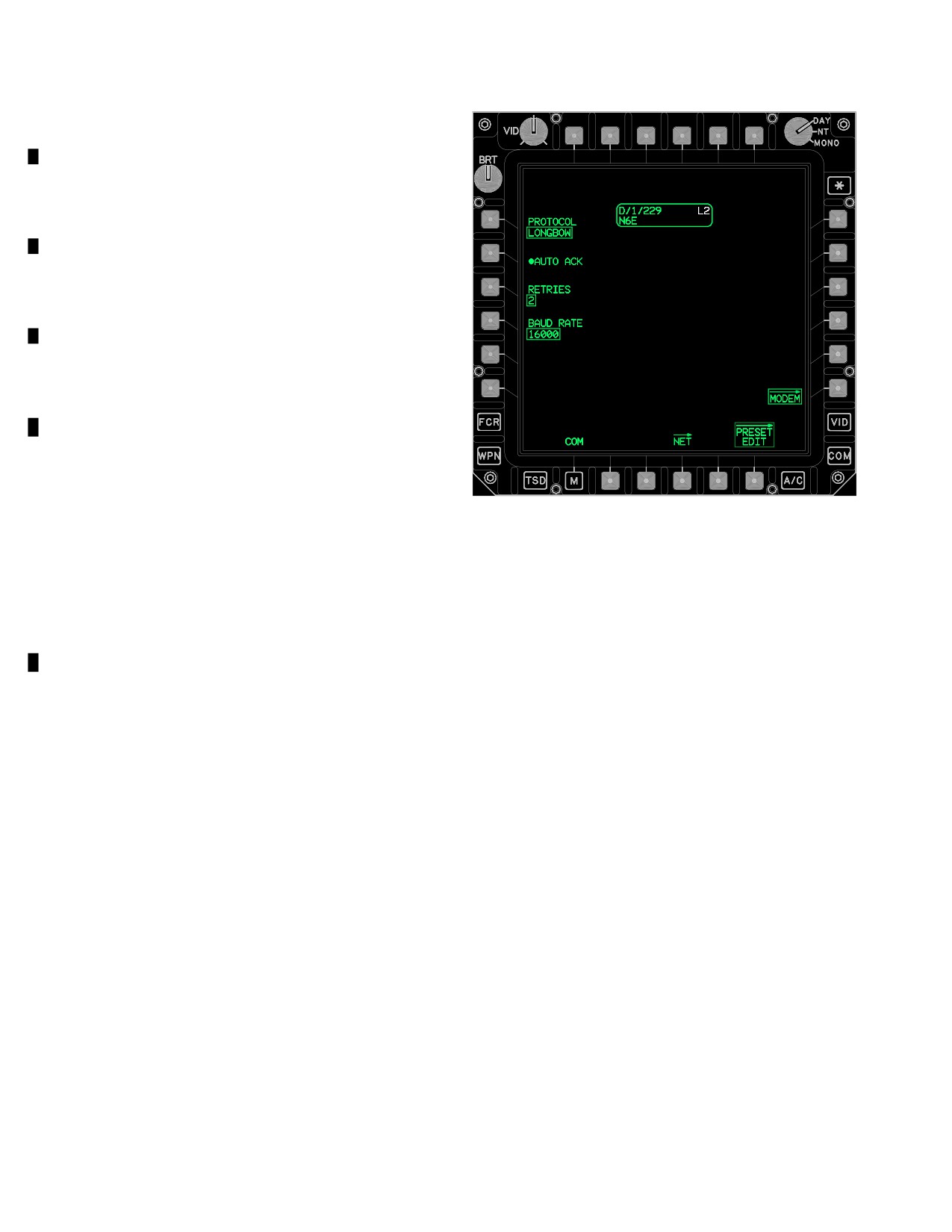
3A.31.2 LONGBOW PROTOCOL. When the multi -
29.9999 MHz, in increments of 100 Hz.
state PROTOCOL button is selected to LONGBOW, the
following unique buttons are displayed:
• AUTO ACK button
3A.30.25 EDIT HF XMIT EMISSION Button. The EDIT
• RETRIES button
HF XMIT EMISSION button changes the HF manual
• BAUD RATE button
transmit emission of the preset between LSB (Lower Side
Band), USB (Upper Side Band), CW (Continuous Wave),
a. AUTO ACK Button. The AUTO ACK button pro-
or AME (Amplitude Modulation Equivalent).
vides the capability to enable or disable the auto acknowl-
edge mode.
b. RETRIES Button. The RETRIES button pro-
3A.31 MODEM PAGE BUTTON
vides the capability to select the number of retransmis-
sions the IDM performs (2, 1, or 0) with no acknowledge-
ment from a subscriber.
The MODEM page button displays the MODEM page.
The MODEM page provides the capability to modify the
c. BAUD RATE Button. The BAUD RATE button
IDM net that is assigned to the PRESET button. The MO-
provides the following baud rate options:
DEM page is accessed by selecting the MODEM page
• 16000
button from the PRESET EDIT or NET page. The selected
• 8000
preset’s current IDM type L, T, I, F, or NONE determines
• 2400
the protocol displayed on the MODEM page.
• 1200
• 600
3A.31.1 PROTOCOL Button. The PROTOCOL button
• 300
(fig 3A-21) provides the capability to select LONGBOW,
• 150
TACFIRE, INTERNET, FIRE SUPPORT or NONE.
• 75
Use or disclosure of this information is subject to the restriction(s) on the title page of this document.
3A-32
Change 3
TM 1-1520-251-10
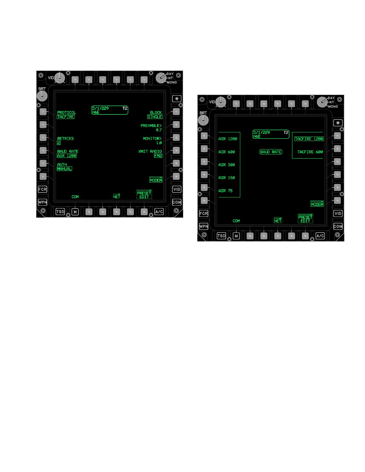
3A.31.3 TACFIRE PROTOCOL. When the multi - state
TACFIRE 1200 and TACFIRE 600 are the only options
PROTOCOL button (fig 3A-22) is selected to TACFIRE, the
available for TACFIRE messages sent to artillery. TAC-
MODEM page displays the TACFIRE PROTOCOL buttons.
FIRE 1200 is the default for the TACFIRE nets. The slow-
er rates for the AIR NETS are to be used only if reception
is poor at high rates.
LBA5097
Figure 3A-22. MODEM Page With TACFIRE
Selected
LBA5098
When the TACFIRE button is selected, the following
unique buttons are displayed:.
Figure 3A-23. MODEM Page With TACFIRE and
• RETRIES button
BAUD RATE Selected
• BAUD RATE button
• AUTH button
c. AUTH Button. The AUTH two - state button al-
• BLOCK button
lows the crew to toggle between NONE and MANUAL. If
• PREAMBLE button
NONE is selected, no authentication is required. This
• MONITOR button
function automatically displays NONE due to use of auto-
matic authentication. If MANUAL is selected, an operator
• XMIT RADIO button
input of the transmission authenticator is required each
a. RETRIES Button. The RETRIES button pro-
time transmission is attempted. MANUAL authentication
vides the capability to select the number of retransmis-
is normally only used in air - to - air or air - to - ground TAC-
sions the IDM performs (2, 1, or 0) with no acknowledge-
FIRE. If MANUAL is selected, but no manual authentica-
ment from a subscriber.
tion is desired at the time of transmission, the message
will be sent on the second press of the SEND button.
b. BAUD RATE Button. The BAUD RATE button
(fig 3A-23) provides baud rate options of:
d. BLOCK Button. The BLOCK two-state button al-
• 1200
lows the crew to toggle between SINGLE and DOUBLE.
• 600
SINGLE BLOCK sends each segment of data once per
• 300
SEND. DOUBLE BLOCK sends each data segment twice
• 150
per SEND. DOUBLE should be used when atmospheric con-
• 75
ditions/reception are poor or when jamming is suspected.
Use or disclosure of this information is subject to the restriction(s) on the title page of this document.
Change 2
3A-33
TM 1-1520-251-10
NOTE
• A minimum preamble of 0.4 seconds is
required when transmitting through cryp-
to equipment. The longer the preamble,
the longer the air time.
• When establishing communications with
AFATDS, ensure that 2.3 seconds is used
by both the AH-64D and the artillery.
e. PREAMBLE Button. The PREAMBLE button is
the ON AIR time that establishes a digital link between the
radios prior to the message being sent. Selecting the
PREAMBLE button provides the capability to modify this
ON AIR time. An interval between 0.1 and 9.9 seconds
may be entered.
f. MONITOR Button. Selection of the MONITOR
button allows the crew to modify the time that the IDM lis-
LBA5099B
tens for interfering traffic prior to transmitting the mes-
sage. A time from 0.5 seconds to 9.9 seconds or OFF may
Figure 3A-24. MODEM Page With FIRE SUPPORT
be entered. To turn this function off the crew must enter
Selected (IDM Mismatch Detected)
zero, the word OFF is displayed on the ATHS page. If
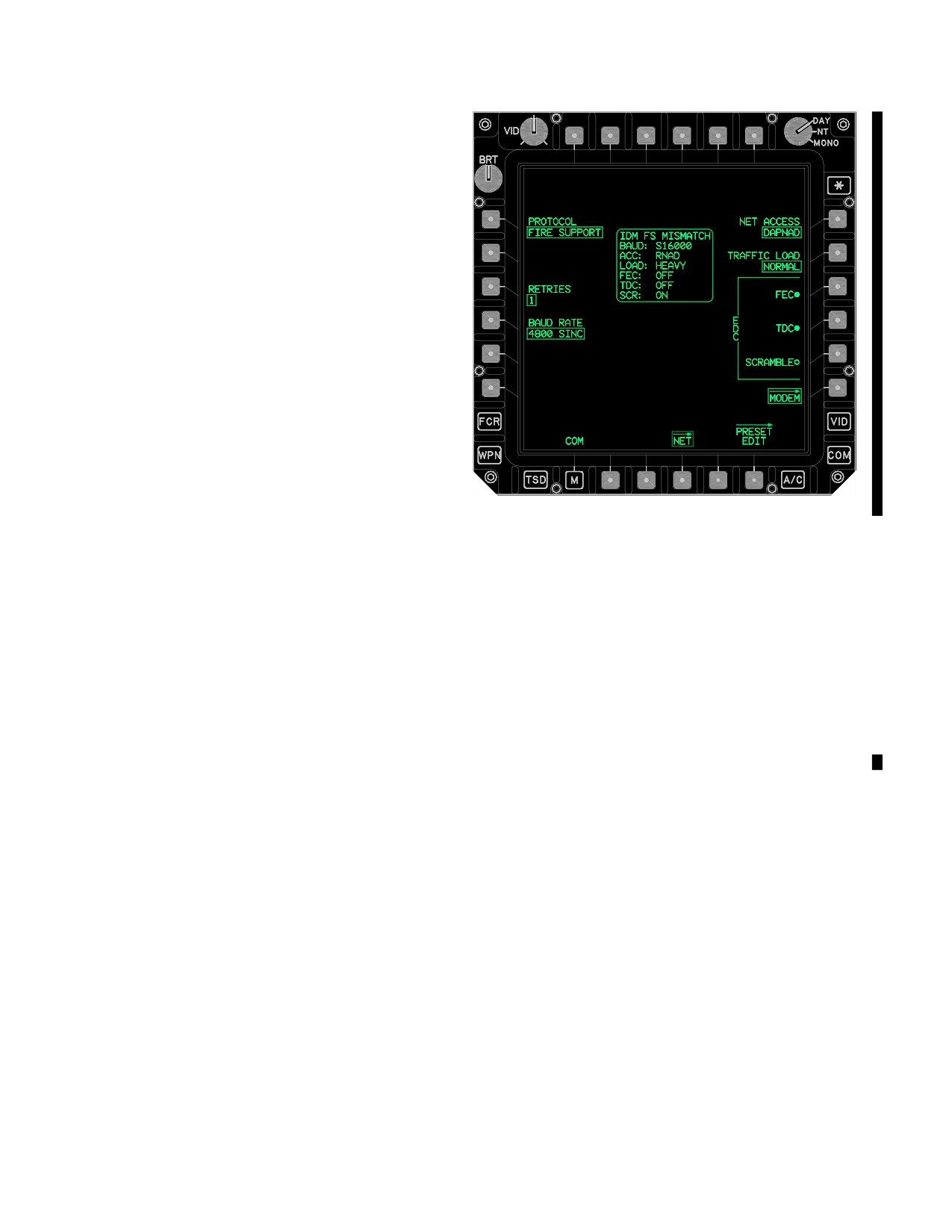
When FIRE SUPPORT is selected, the following unique
more than 15 seconds have elapsed after the SEND but-
buttons are displayed:
ton has been depressed, the IDM will reset automatically
and the SEND button must be pressed again. Voice trans-
• BAUD RATE button
mission has priority over digital transmission; therefore,
• NET ACCESS button
the IDM will wait until the airway is clear of voice traffic if a
• TRAFFIC LOAD button
monitor time has been selected.
• EDC FEC button
• EDC TDC button
• EDC SCRAMBLE button
g. XMIT RADIO Button. Selection of the multi -
state XMIT RADIO button allows the crew to select the ra-
• RETRIES button
dio that the IDM will use to transmit the TACFIRE digital
a. BAUD RATE Button. The BAUD RATE button
messages. Preset options of VHF, UHF, FM1, and FM2
(fig 3A-25) specifies the baud rate and the mode for the
are displayed upon selection of of the XMIT RADIO but-
currently selected preset’s IDM Net which will be used for
ton. When the preset is selected and tuned to a radio, that
sending and receiving fire support data. The button pro-
radio will be set at XMIT RADIO. After the preset has been
vides options of the following SINC BAUD RATES:
tuned to a radio, this button allows the operator to config-
• 16000
ure it to a different radio. Artillery TACFIRE nets are nor-
mally set on FM1 or FM2.
• 4800
• 2400
• 1200
3A.31.4 INTERNET PROTOCOL Button. When the
• 600
multi - state PROTOCOL button is selected to INTERNET,
no unique button is displayed.
The button provides options of the following ENHANCED
BAUD RATES:
• 9600
3A.31.5 FIRE SUPPORT PROTOCOL Button. When
• 4800
the PROTOCOL button (fig 3A-24). is selected to FIRE
• 2400
SUPPORT, the MODEM page displays the FIRE SUP-
PORT PROTOCOL buttons.
• 200
Use or disclosure of this information is subject to the restriction(s) on the title page of this document.
3A-34
Change 3
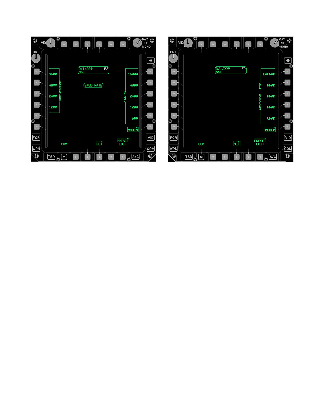
TM 1-1520-251-10
LBA5100
LBA5101
Figure 3A-26. MODEM Page With FIRE SUPPORT
NET ACCESS Selected
Figure 3A-25. MODEM Page with FIRE SUPPORT
c. TRAFFIC LOAD Button. The TRAFFIC LOAD
BAUD RATE Selected
button provides the means to select 1 of 3 TRAFFIC
LOAD button options for use with the preset selected. The
TRAFFIC LOAD button options set the flow control pa-
rameter size. Button options include:
• HEAVY
b. NET ACCESS Button. The NET ACCESS but-
ton (fig 3A-26) provides the means to select 1 of 5 net ac-
• NORMAL
cess delay methods that the IDM will use with the selected
FIRE SUPPORT preset. The presence of multiple mem-
• LIGHT
bers on a single net requires a method of controlling the
transmission opportunities for each member. The net ac-
A HEAVY TRAFFIC LOAD selection places a greater
cess delay selections detect when the net is busy and reg-
loading on a single channel. NORMAL TRAFFIC LOAD
ulate transmission opportunities over the net. Modes in-
should be selected unless FS has instructed otherwise.
clude the following selections:
d. EDC FEC/TDC/SCRAMBLE Buttons. The ER-
• DAPNAD
ROR DETECTION CORRECTION (EDC) On and Off but-
tons provide the means for configuring the error detection
• RNAD
parameters that the IDM will use with the FIRE SUPPORT
protocol for the preset selected. EDC On/Off buttons in-
clude FEC, TDC, and SCRAMBLE.
• PNAD
• FEC (Forward Error Correction) coding provides
• HNAD
IDM Error Detection and Correction (EDC) capa-
bilities to compensate for errors induced during
• VNAD
transmission.
Use or disclosure of this information is subject to the restriction(s) on the title page of this document.
Change 2
3A-35
TM 1-1520-251-10
NOTE
3A.32 PRESET DIR PAGE
When an ENHANCED baud rate (Error Detect
The PRESET DIR page (fig 3A-27) accesses a pre - mis-
Control mode internal to the radio) has been
sion developed database of up to 60 digital/voice PRE-
selected, FEC On should not be used; howev-
SET items. The PRESET DIR page supports manual
er, the NET parameters are determined by the
page searching, KU data searching, the selection of
Fire Support NET administrator.
single PRESET items, and the replacement of COM page
presets with PRESET items. The PRESET DIR page but-
• TDC (Time - Dispersive Coding) bit interleaving
ton is displayed following a DTU load and is accessed via
formats data into TDC blocks. TDC reduces bit
the PRESET DIR button presented on either the COM
errors during the transmission of messages. All
page or SOI page.
Fire Support protocol compliant receivers have
TDC decoder capabilities to translate: FEC with
TDC, or FEC with TDC and SCRAMBLE.
NOTE
The AH- 64D is DC response compliant. En-
able SCRAMBLE only when briefed by the
artillery NET administrator. SCRAMBLE
supports legacy systems that are not yet
JVMF - FS enabled.
• SCRAMBLE (Data scrambling) is required any-
time that a Fire Support NET transmitter element
does not have a DC response capability and there
is the possibility that long strings of ones or zeros
could be transmitted.
e. RETRIES. The RETRIES button (fig 3A-24) pro-
vides the capabiilty to select the number of FS retransmis-
sions the IDM performs (2, 1, or 0) with no acknowledgement
from the subscriber.
f. IDM FS MISMATCH Status Window. The IDM FS
LBA5102A
MISMATCH status window (fig 3A-24) displays the mismatch
status for Fire Support IDM parameters. This status window
Figure
3A-27.
PRESET DIR Page
is only displayed when Fire Support is tuned to one of the ra-
dios and the IDM is reporting one of the parameters is differ-
ent from what was commanded by the DP. Potential Fire
The PRESET DIR page contains the following unique but-
Support mismatch parameters include:
tons:
• FS Baud Rate
• T5
REPLACE button
• L1 - L5
PRESET buttons
• Net Access
• R1 - R5
PRESET buttons
• Traffic Load
• B2
PAGE BACK button
• EDC
• B3
PAGE FORWARD button
• B5
ABORT button (conditional)
The status window represents the current IDM configura-
tion.
• B6
SRCH button
Use or disclosure of this information is subject to the restriction(s) on the title page of this document.
3A-36
Change 4
TM 1-1520-251-10
NOTE
3A.32.2 PRESET Buttons. The PRESET DIR page
button provides access to a premission developed data-
Selecting the PRESET REPLACE location
base containing up to 60 PRESET items. Each of the
9 or 10 with a Longbow or Tacfire PRESET
PRESET items possess identical data type capabilities
item will store the COM and member data,
and capacities as does the COM page presets inclusive of
however, the net-type will be changed to
members. Upon the display of the page, the first valid
voice. Preset 9 and 10 will only digitally sup-
PRESET item will be selected and the corresponding
port Fire Support and Internet protocols,
PRESET item status window (para 3A.32.3 and fig 3A-27)
while presets 1 through 8 may be used with
is displayed along with the PRESET item MEMBER status
any protocol.
window. Each PRESET item button contains two lines of
information, with the first line containing the Unit ID field
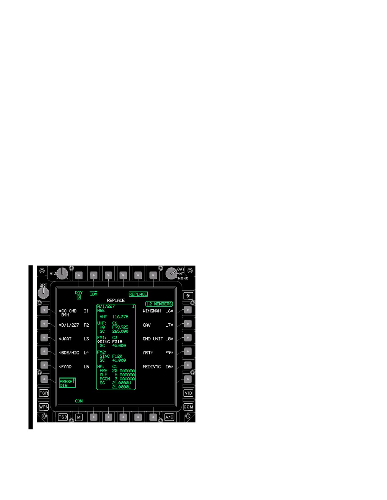
3A.32.1 REPLACE Button. The PRESET DIR LOCA-
and the digital protocol fields. The second line contains
TION REPLACE format is displayed when the REPLACE
the Unit Call Sign field. The digital protocol assignment is
button (fig 3A-28) is selected. This display format provides
represented by the presence of either an L (Longbow), T
the means to replace any one of the ten COM page pre-
(TACFIRE), I (Tactical Internet), or F (Fire Support) which
sets with the selected PRESET item. When the selected
indicates the current protocol of the selected PRESET
PRESET item is assigned with a Longbow or Tacfire pro-
Item.
tocol, the REPLACE PRESET location display button
locations 1 through 8 are white while presets 9 through10
3A.32.3 PRESET ITEM Status Window. The PRESET
are green. When the selected PRESET item is assigned
item status window (fig 3A-27) displays the field contents
an Internet or Fire Support protocol, all presets are dis-
of the currently selected PRESET item. The primary radio/
played in white. The selection of any one of the PRESET
mode and frequency/ECCM will be displayed in white.
REPLACE location buttons commands the replacement
Status window data fields includes:
of that locations COM page preset with the selected PRE-
SET items COM, IDM, and member data. Following the
• Unit ID
system’s successful processing of the replace - store op-
eration, the COM page will display showing that the re-
• Call Sign
place was made.
IDM Type and IDM Preset - Net Number
•
• VHF Frequency
• UHF CNV status
• UHF HQ Net number
• UHF Single Channel Frequency
• FM1 CNV status
• FM1 SINC net number
• FM1 Single Channel Frequency
• FM2 CNV status
• FM2 SINC net number
• FM2 CNV status
• HF CNV status
• HF PRE
LBA5103A
• HF ALE
• HF ECCM
Figure
3A-28.
PRESET DIR - REPLACE Button
Selected
• HF SC
Use or disclosure of this information is subject to the restriction(s) on the title page of this document.
Change 4
3A-37
TM 1-1520-251-10
3A.32.4 PRESET ITEM MEMBER Status Win-
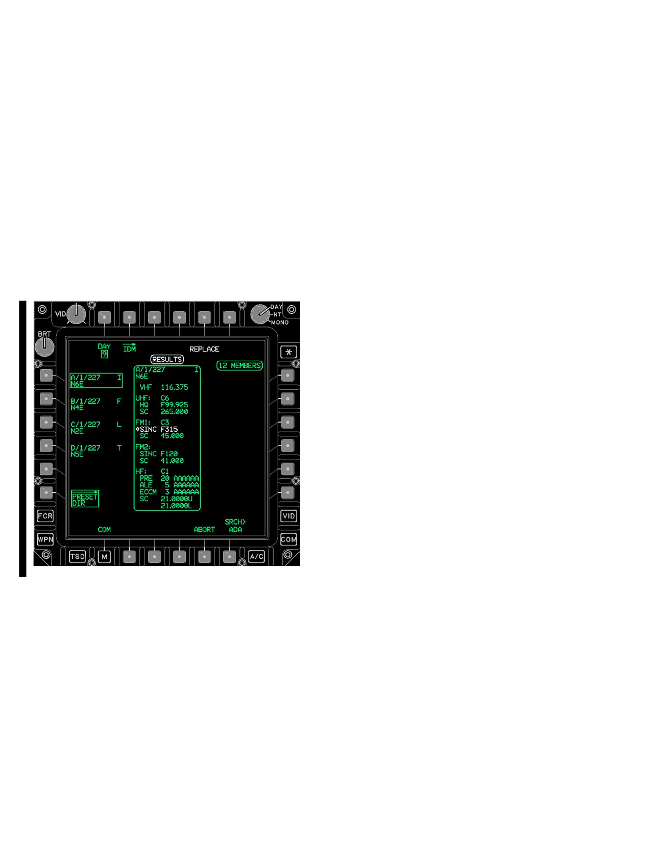
The PRESET DIR page with search RESULTS posted
dow. The PRESET item MEMBER status window (fig
has the following unique button:
3A-27) displays the quantity of existing members for the
• B5
ABORT button
selected PRESET item. The status window displays the
PRESET item’s total member count field status as a num-
3A.32.6 SRCH Button. The PRESET ITEM SEARCH
ber of 0 through 15 followed by MEMBERS. PRESET item
data entry button provides the means to search for a spe-
members are not editable from the PRESET DIR page.
cific preset item in the preset directory’s database.
Searching and replacing functionality provides the means
to quickly replace Longbow, Tacfire, Tactical Internet, Fire
3A.32.5 ABORT Button. The ABORT button (fig
Support, and Voice presets. The keyboard label reads
3A-29) provides the means to abort a search during OIP
PRESET SEARCH and the data entry may be all or a por-
or after search is complete. The ABORT button is dis-
tion of either the Unit ID or Call Sign of a preset. PRESET
played when a search is initiated. Aborting a search re-
item search will begin following the selection of KB EN-
stores the PRESET item page list and resets the page
TER key and an ABORT button will display at this time.
number to one.
3A.32.7 SRCH RESULTS Format. The PRESET DI-
RECTORY page posts and displays matched search re-
sults as they occur in a SEARCH RESULTS format. The
RESULTS status window (fig 3A-29) is displayed during a
search to reflect that the PRESET items being displayed
are matches to search data. Posted preset results may be
reviewed and stored while the search continues. The
PRESET list buttons control presentation of search result
pages. If there are 10 or less PRESET item matches
found in a search, then the page buttons will not be dis-
played.
3A.32.8 NO MATCH Status Window. The NO MATCH
status window is displayed when there was no match
found during a preset PRESET DIR database item
search. When called, the NO MATCH status will be dis-
played in white in the location immediately above the
SRCH button.
3A.33 NET PAGE
The NET page displays the preset member data associat-
ed with the selected COM page preset - net, provides edit-
ing for 1 to 15 members for Longbow, Tacfire, Internet,
LBA5104A
Fire Support, and NONE protocols, and provides access
to the MBR DIR page. Additionally, it provides advisory
status windows for the selected net member’s Callsign/
Figure
3A-29.
PRESET DIR Page - Database SRCH
Suffix status and IDM digital ID settings and an abbrevia-
With RESULTS Posted
ted ownship (para 3A.23.15) status window.
Use or disclosure of this information is subject to the restriction(s) on the title page of this document.
3A-38
Change 4
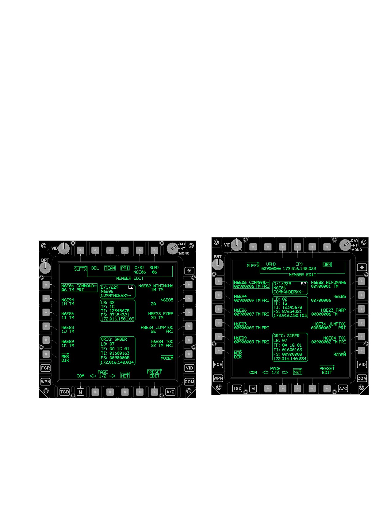
TM 1-1520-251-10
The NET (LONGBOW, TACFIRE, TI, Fire Support and
3A.33.2 MEMBER DEL Button. The MEMBER DEL
NONE) page (fig 3A-30) has the following unique buttons:
button provides the capability to delete the selected mem-
ber. This button is only displayed for a preset with an as-
• T1
SUFFX (Suffix) button
signed IDM net and a valid call sign as displayed in the
• T2
DEL (MEMBER) button
MEMBER CALL SIGN button. Selection of the MEMBER
DEL button will prompt for a YES or NO confirmation to
• T2
URN (Fire Support) button
initiate the deletion. Selecting the YES confirmed button
• T3
TEAM button
deletes the data associated with the selected MEMBER
button and returns the crewmember out of the member
• T4
PRI button
delete confirmation mode. Selecting NO returns the crew-
• T4
IP (Fire Support) button
member out of the member delete confirmation mode.
• T5
C/S button
3A.33.3 MEMBER URN (Fire Support) ID But-
• T6
SUB (Longbow/Tacfire) button
ton. The net MEMBER FS Unit Reference Number ID
• T6
URN (Internet) button
data entry button (fig 3A-31) provides the capability to edit
or create the selected net member’s URN ID. The net
• L1-L5
MEMBER buttons
URN ID button is displayed whenever a Fire Support net
• L6
MBR DIR button
MEMBER button is selected and the the URN maintained
• R1-R5
MEMBER buttons
option button is selected. Each member’s URN ID is
mapped to its respective Internet Protocol (IP) address
• R6
MODEM button
(para 3A.33.6) through the net MEMBER FS IP ID ad-
• B2
PAGE Back button
dress data entry button. When selected, the keyboard la-
• B3
PAGE Forward button
bel will display FS URN ID and will accept an entry of 0
through 16,777,215.
• B5
CLEAR (Tacfire only) button
LBA5106
LBA5105
Figure 3A-31. NET Page - (Fire Support Net
Figure 3A-30. NET Page - (Longbow Team Member
Member Selected, URN Selected Edit Mode)
Selected)
3A.33.4 MEMBER TEAM Button. The TEAM button
3A.33.1 SUFFX Button. The SUFFX button displays
provides the capability of toggling a net member’s team
the SUFFX page (para 3A.33.17).
designation on or off. Selecting the TEAM button assigns
Use or disclosure of this information is subject to the restriction(s) on the title page of this document.
Change 2
3A-39
TM 1-1520-251-10
and unassigns team member status independently of the
3A.33.9 MEMBER URN (Internet) ID Button. The net
PRI (primary) status. Selecting the TEAM button will add
MEMBER URN Internet ID data entry button (fig 3A-31)
the selected member to the IDM net associated with the
provides the capability to edit or create the selected net
currently displayed preset and display the TM status on
member’s URN ID. The net URN ID button is displayed
the second field of the selected MEMBERs button. This
whenever an Internet protocol net MEMBER button is se-
button is only displayed if the net member currently se-
lected and the the URN maintained option button is se-
lected has a subscriber or URN digital ID.
lected. When selected, the keyboard label will display FS
URN ID and will accept an entry of 0 through 16,777,215.
3A.33.5 MEMBER PRI Button. The PRI (primary) but-
ton provides the capability to toggle a net member’s pri-
3A.33.10 MEMBER Buttons. The member buttons
mary designation on or off. Selecting the PRI button as-
provide the capability to create, edit, and assign/unassign
signs and unassigns primary member status
team and priority member status for up to 15 IDM preset
independently of the TEAM status. Selecting the PRI but-
net members or create/edit up to 15 voice net members.
ton will add the selected member to the IDM net associat-
The preset net MEMBER buttons contain two fields of in-
ed with the currently displayed preset and display the PRI
formation. The first field contains the Call Sign ID and Suf-
status on the second field of the selected MEMBER’s but-
fix Description. The second field contains the Digital ID,
ton. This button is only displayed if the net member cur-
Team Status, and Primary Status. The Call Sign ID is dis-
rently selected has a subscriber or URN digital ID and if
played with up to a five character free text descriptor. The
there are not already seven members designated as pri-
Suffix Description is displayed with up to the first eight
mary members.
characters of the free text descriptor. When selected, a
preset net member status window (para 3A.33.15) and
3A.33.6 MEMBER IP (Fire Support) ID Button. The
net member IDM status window (para 3A.33.16) will be
net MEMBER FS IP ID data entry button provides the ca-
displayed providing a display of the selected member’s
pability to edit, or create, the selected member’s Fire Sup-
COM and digital data.
port IP ID. The net MEMBER FS IP ID button is displayed
whenever a Fire Support net MEMBER button is selected
and the the URN maintained option button is selected.
3A.33.11 MODEM Page Button. The MODEM button
The Fire Support protocol’s IP address ID is mapped to
displays the MODEM page (para 3A.31).
the member’s Fire Support URN ID number (para
3A.33.3) through the net MEMBER URN ID data entry
button. When selected, the keyboard label will display FS
IP with four fields separated by three decimals and each
3A.33.12 MBR DIR Page Button. The MEMBER DI-
field will accept an entry of 0 through 255.
RECTORY page button displays the member directory
page (para 3A.34).
3A.33.7 MEMBER C/S Button. The MEMBER C/S
data entry button provides the capability to edit or create
the selected members call sign. This button is only dis-
played for a preset with an assigned IDM net. When se-
3A.33.13 PAGE Back and PAGE Forward But-
lected, the keyboard label will display CALL SIGN and will
tons. Allows selection between two pages of preset
accept an entry of 3 to 5 characters.
members.
3A.33.8 MEMBER SUB (Longbow/Tacfire) ID But-
ton. The preset net MEMBER SUB ID data entry button
provides the capability to edit, or create, the selected
3A.33.14 CLEAR (TACFIRE) Button. The CLEAR but-
members Longbow or Tacfire preset net subscriber ID.
ton, displayed in white, is only displayed if the IDM has de-
The preset net MEMBER SUB ID button is displayed
tected extraneous Tacfire subscribers. This may occur if
upon the selection of a MEMBER button and Longbow or
the crew deletes subscribers from a Tacfire net, but then
Tacfire is the selected protocol. The keyboard label dis-
performs an upload of the original Tacfire member data
plays SUBSCRIBER ID and accepts a one or two charac-
from the DTC. Pressing the CLEAR button will delete the
ter input between 0 - 39, A - Z, 1A - 1Z, 2A - 2Z, or 3A - 3I.
extraneous Tacfire subscribers from the IDM.
Use or disclosure of this information is subject to the restriction(s) on the title page of this document.
3A-40
Change 2
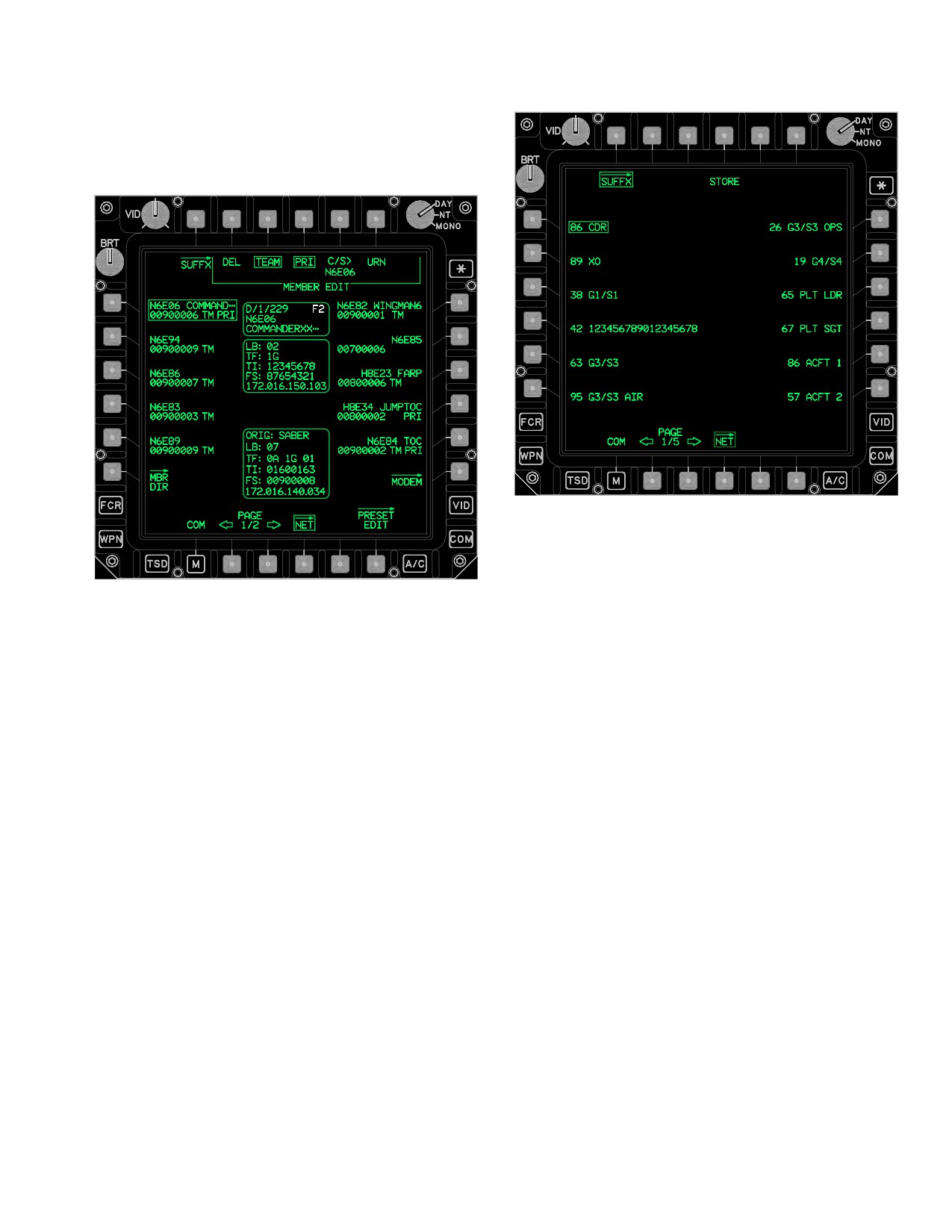
TM 1-1520-251-10
3A.33.15 MEMBER Status Window. The net MEM-
BER status (fig 3A-30, 3A-31, and 3A-32) is displayed
when a net MEMBER is selected.
LBA5108
LBA5107
Figure 3A-33. SUFFX Page - (Net Member
Selected)
Figure 3A-32. NET Page - (Fire Support Net
Member Selected)
The SUFFX page contains the following unique buttons:
The status window contains 3 fields:
• T4
STORE button
• L1-L6
Suffix buttons
• Unit ID and Net Protocol
• Call Sign
• R1-R6
Suffix buttons
• Suffix Descriptor.
• B2
PAGE Back button
• B3
PAGE Forward button
3A.33.16 MEMBER IDM Status Window. The net
MEMBER IDM status (fig 3A-30, 3A-31, and 3A-32) win-
dow is displayed when a net MEMBER is selected. The
3A.33.18 STORE Button. Selecting the STORE button
status window contains five fields:
provides the capability to store the selected Suffix into a
selected preset net member button location on the NET
• LB (Longbow subscriber ID)
page. Also as part of this selection, a new subscriber call
sign for the NET MEMBER selected is created using the
• TF (Tacfire subscriber ID)
selected Preset’s call sign and the selected Suffix ID. This
• TI (Tactical Internet URN ID)
button is displayed in white.
• FS (Fire Support URN ID)
• XXX.XXX.XXX.XXX (FS IP Address)
3A.33.19 Suffix Buttons. The Suffix buttons are dis-
played on the left and right sides of the SUFFX page.
3A.33.17 SUFFX Page Button. The SUFFX page (fig
3A-33) displays the Suffix data that has been loaded from
the DTC. The SUFFX page provides the capability to
3A.33.20 PAGE Back and PAGE Forward But-
modify members with a suffix.
tons. Allows selection of multiple pages of suffixes.
Use or disclosure of this information is subject to the restriction(s) on the title page of this document.
Change 2
3A-41
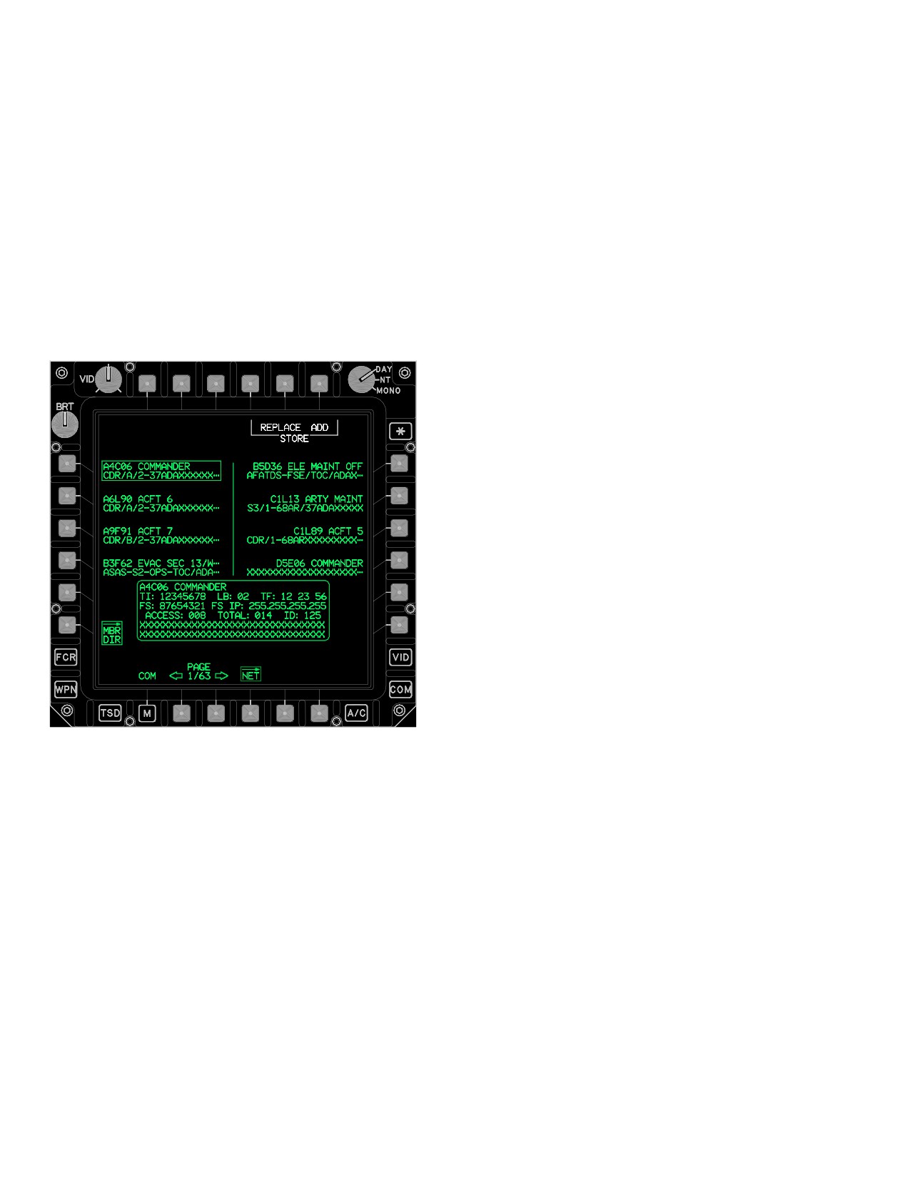
TM 1-1520-251-10
3A.34 MBR DIR PAGE
3A.34.1 STORE REPLACE Button. The STORE RE-
PLACE button presents the NET LOCATION STORE
Page format (para 3A.34.11).
The MEMBER DIRECTORY page (fig 3A-34) is capable
of maintaining a 500 member data base (directory), and
provides the capability to page search, auto search, and
3A.34.2 STORE ADD Button. The STORE ADD but-
add or replace preset net members into a digital net. The
ton stores the selected MEMBER (database item) to the
member directory data base is developed during premis-
first vacant NET page MEMBER location (para 3A.34.12).
sion planning and is loaded from the DTC. The MBR DIR
page is accessed via the NET page. Member automatic
3A.34.3 MEMBER Buttons. The MEMBER buttons
search and store functionality provides the operator with
represent the digital members that have been loaded in
the capability to quickly build Longbow, Tacfire, Tactical In-
the Member Directory and are not associated with the SOI
ternet, and Fire Support digital nets.
database. The display ordering of members (i.e., 1
through 500) is determined by how the database was es-
tablished during premission planning. The MEMBER but-
ton format consists of three fields:
• Call sign
• SUFFIX
• URN descriptor’s first 20 characters of up to 64
characters located beneath the callsign
3A.34.4 MEMBER Review Status. Window. The
MEMBER Review status window (fig 3A-34) displays
when a MEMBER button is selected. The status window
displays all the database elements for the selected MEM-
BER button and consists of six lines with 13 data fields.
The MEMBER Review status window contains the follow-
ing unique data fields:
• Callsign and Suffix
• TI URN ID, LB ID, TF ID, TF TM ID, and
LBA5109
TF BCST ID
• FS URN ID, FS IP ID
Figure
3A-34.
MBR DIR page
•
ACCESS###, TOTAL ###, ID###
• URN Descriptor, first 32 characters
The MBR DIR page contains the following unique buttons:
•
URN Descriptor, second 32 characters
• T5
STORE REPLACE button
3A.34.5 PAGE Back and PAGE Forward But-
• T6
STORE ADD button
tons. The PAGE Back and Forward buttons permit the
• L1-L4
MEMBER buttons
manual selection of the member directory pages for locat-
ing members.
• R1-R4
MEMBER buttons
• B2
PAGE BACK button
3A.34.6 ABORT Button. The ABORT member search
• B3
PAGE FORWARD button
button provides the capability to abort a search during an
active database search or, after a search has completed,
• B5
ABORT button (Conditional)
it may be selected to return to the page search format (pa-
• B6
SRCH button (Conditional)
ra 3A.34.7 and 3A.34.8 and fig 3A-35).
Use or disclosure of this information is subject to the restriction(s) on the title page of this document.
3A-42
Change 2
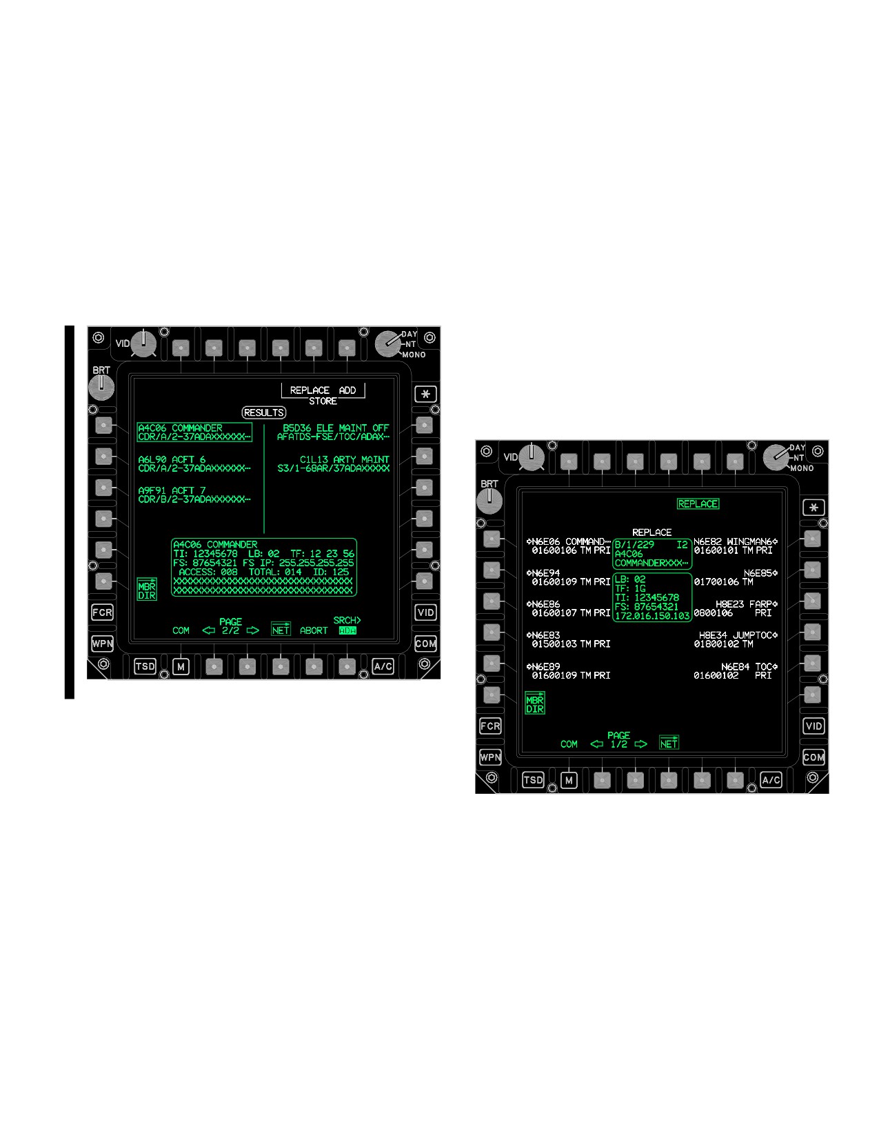
TM 1-1520-251-10
3A.34.7 SRCH Button. The Member Search data entry
3A.34.10 NO MATCH STATUS Window. The NO
button provides the capability to initiate a search for a spe-
MATCH status window displays when there is not a
cific member or a group of members. When the SRCH
search match made in the Member Directory. The status
button is selected, the KU label displays MBR SEARCH
will be displayed in white, replacing the SRCH status bar.
and the data entered may be all or a portion of the Call
Sign, or up to any 8 sequential characters of the 64 char-
3A.34.11 STORE REPLACE Button. The STORE RE-
acter URN Descriptor. During a search, results are posted
PLACE button presents the Net Member location format.
and displayed (fig 3A-35) in a RESULTS format. If there is
All fifteen Net Member locations will display in white with
no match made during the search, then the NO MATCH
an arrow to identify that they are available for storage. The
status window (para. 3A.34.10) is displayed in white just
REPLACE status window (fig 3A-36) is displayed in white
above the SRCH button.
at the top center of the net member location format. The
Member Selected status window displays the selected
Member Directory item’s data that has been selected for
replacement storage. When a Net Member location button
is selected that had contained a preexisting net member,
that member will be replaced with the new member. Fol-
lowing a Net Member location REPLACE selection, the
NET page will display with the preset - net member that
was just stored selected.
LBA5110A
Figure 3A-35. MBR DIR RESULTS Format
3A.34.8 SRCH RESULTS Format. The Member Direc-
LBA5111
tory page posts and displays matched search results as
they occur in a SRCH RESULTS format. The RESULTS
Figure 3A-36. MBR DIR REPLACE Item Location
status window (fig 3A-35) is displayed during a search to
Format
reflect that the Member Directory listings being displayed
are matches to search data.
3A.34.12 STORE ADD Button. The STORE ADD but-
ton stores the selected member to the first open net loca-
3A.34.9 MBR SRCH Status Bar. The member SRCH
tion of the selected preset. When all net locations for a
status bar graphic provides awareness of the overall
preset are filled with members (i.e., 15 locations), the
search progress. There are 25%, 50%, and 75% complete
ADD button will barrier. The Member Store Location Sta-
hatch marks for quick assessment of the searching prog-
tus window displays, in white, when a member was suc-
ress. Posted member results may be reviewed and stored
cessfully added to the preset - net. The status window dis-
while the search continues. Page buttons will not display
plays the available NET member location that the
until the ninth result is posted.
selected Directory Member was stored to.
Use or disclosure of this information is subject to the restriction(s) on the title page of this document.
Change 3
3A-43
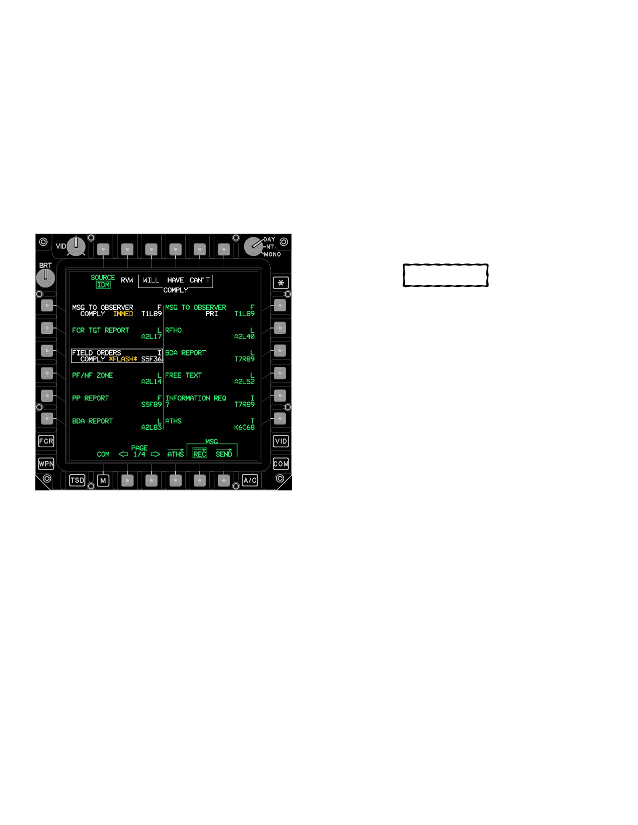
TM 1-1520-251-10
3A.35 MSG REC PAGE
• R1-R6
Message Receive buttons
• B2
PAGE Back button
The MSG REC page (fig 3A-37) provides the operator the
capability to manage IDM messages that are received
• B3
PAGE Forward button
within the IDM’s message receive buffer or to manage HF
• B4
ATHS Page button
messages that are received within the HF radio’s receive
buffer. The crew is cued when a message is received by a
NOTE
EUFD advisory, message receive tone (para 2.139, table
2-15) and the message appearing on the MSG REC page.
Storage of an IDM message will overwrite
Additionally, Longbow messages received containing
the selected mission data.
TSD data and JVMF C2 messages will cue the crew by
displaying a RCVD button on the TSD page.
3A.35.1 SOURCE Button. The SOURCE button
toggles between IDM or HF message receive controls and
messages.
CAUTION
Storing a BLOCK 01 COM ALL IDM/SOI file
message will delete all Tactical Internet and
Fire Support data for the current preset-
nets. If this occurs, the COM presets will
have to be reloaded.
3A.35.2 STORE/RVW Button. The STORE/RVW button
provides the capability to store a data message or review
(para 3A.35.9) a FREE TEXT (Longbow or Internet), FIELD
ORDERS (Internet or Fire Support), or INFORMATION RE-
QUEST (Internet or Fire Support) message, or any ATHS
message received via the IDM. The STORE and RVW but-
tons will display after an applicable message has been se-
lected. The STORE button will not display if the selected In-
ternet or Fire Support message was not properly formatted
by the sender. The STORE button stores the data associated
LBA5073
with the selected Message button and then deletes the mes-
sage from the IDM buffer unless the Internet message send-
Figure
3A-37.
MSG REC Page (Source IDM)
er requested a compliance message. When an operator ack-
nowledgement (ACK) is requested by the Internet or Fire
Support message sender, an operator ACK message is
The MSG REC page contains the following unique but-
transmitted at the time that the message is either stored or
tons:
reviewed unless the IDM has been inhibited. If a TACFIRE
• T2
SOURCE button
message is selected for review, then upon activation of the
RVW button the page will automatically switch to the page
• T2
STORE/RVW button
MSG RCVD page of the ATHS TACFIRE. Refer to the ATHS
• T3
LOCATION CURR button (Longbow)
section for more information.
• T3
COMPLY WILL button (JVMF)
3A.35.3 LOCATION CURR / MSN1 / MSN2 Buttons. The
• T4
LOCATION MSN1 button (Longbow)
MSG REC page CURR, MSN1, and MSN2 buttons (fig
• T4
COMPLY HAVE button (JVMF)
3A-38) provide the capability to specify where a Longbow
• T5
LOCATION MSN2 button (Longbow)
message file, or files, will be stored. Selecting the CURR but-
ton will store the selected Longbow message or messages
• T5
COMPLY CAN’T button (JVMF)
to the current (active) locations and displays. Selecting the
• T6
DEL button
MSN1 or MSN2 buttons will store the message, or mes-
• L1-L6
Message Receive buttons
sages, to either MISSION1 or MISSION2 on the DTC.
Use or disclosure of this information is subject to the restriction(s) on the title page of this document.
3A-44
Change 2
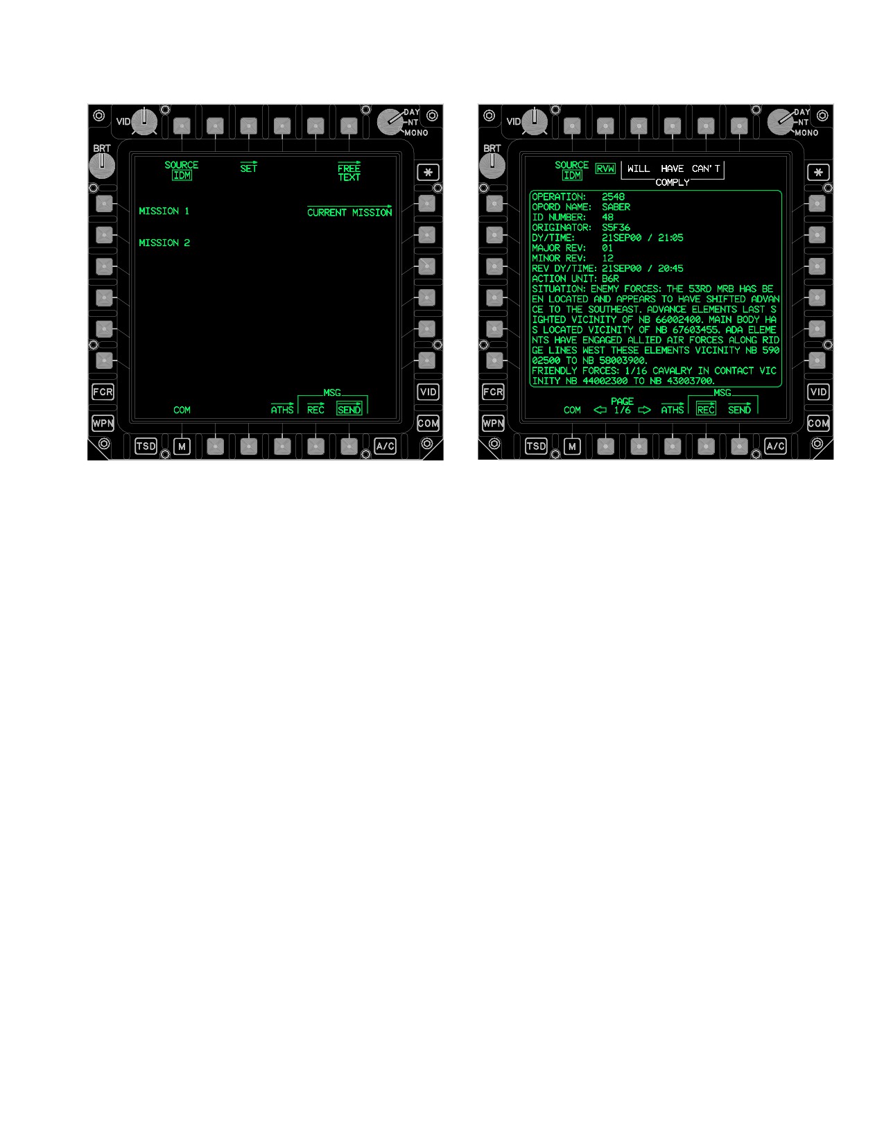
TM 1-1520-251-10
LBA5074
LBA5075
Figure 3A-39. Message Buttons (FIELD ORDER
Selected)
3A.35.5 DEL Button. Selecting the DEL button deletes
the IDM message associated with the selected message
button. When a compliance is requested by an Internet or
Fire Support message sender, the DEL button will not be
displayed until either the WILL, HAVE, or CAN’T COM-
PLY button has been selected.
Figure 3A-38. IDM Page
3A.35.6 Message Buttons. There can be up to 12 mes-
sage buttons per page (fig 3A-37) and up to 13 pages. On
the top line, the type of message will be displayed, along with
the protocol the message was received on. If the message is
not valid per the indicated type a “?” will be displayed at the
NOTE
beginning of the second line. If the sender of the message
requested an operator response, the second line, toward the
The LOCATION MSN1 or MSN2 buttons are
beginning, will display the word COMPLY and the message
barriered anytime that a Longbow data mes-
will be displayed white. The priority cue is displayed in the
sage is selected and the mission card is not
middle of the second line if the sender of the message placed
available, corrupt, or busy with a different task.
a higher priority than routine on the message. A message
with the priority cue of priority would display PRI in white, a
priority of immediate would display IMMED in yellow, a priority
of flash would display FLASH in yellow, and a priority of
3A.35.4 COMPLY WILL/HAVE/CAN’T Buttons. The
emergency would display EMERG in yellow. The call sign of
the sender is displayed at the end of the second line. If the
WILL, HAVE, and CAN’T buttons (fig. 3A-39) are dis-
sender is a subscriber to one of the presets, the call sign will
played when the sender of the selected Internet or Fire
be displayed, otherwise a “?” will be displayed. New incoming
Support message requested an operator compliance re-
messages are displayed at the end of the buffer.
sponse, the selected message has been reviewed or
stored, and one of the radios is tuned to either the Fire
3A.35.7 PAGE Back and PAGE Forward Buttons. Al-
lows selection of multiple pages of received IDM messages.
Support or Internet protocols. When one of the WILL,
HAVE, or CAN’T buttons is selected, a message with the
3A.35.8 ATHS Page Button. The ATHS button (fig
corresponding response will be sent back to the sender.
3A-39) displays the ATHS page.
Use or disclosure of this information is subject to the restriction(s) on the title page of this document.
Change 2
3A-45
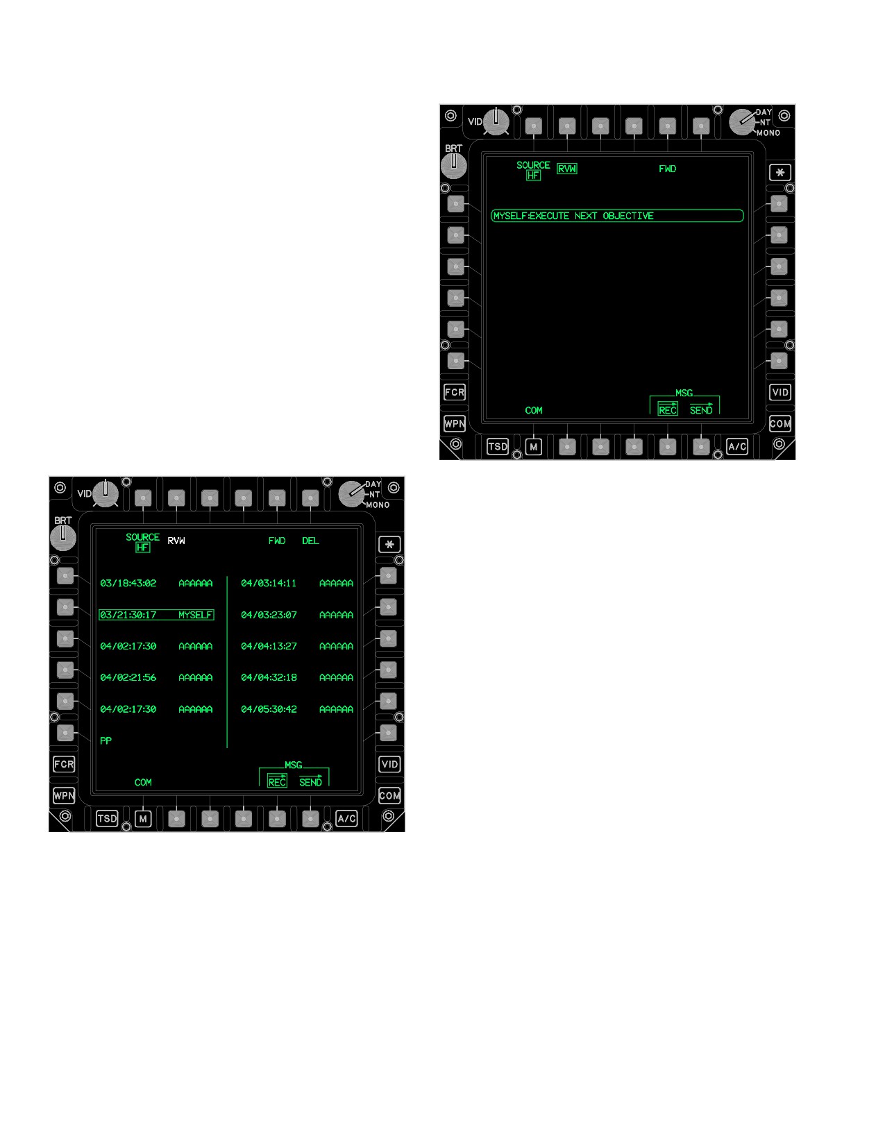
TM 1-1520-251-10
3A.35.9 RVW Message Window. The RVW message
window (fig 3A-39) allows the crewmembers to review text
based messages (Free Text, Field Orders, and
Information Request messages) received over the IDM.
The status window can display up to 19 lines of 44
characters. When used with the PAGE Back and PAGE
Forward buttons, up to six pages of a message can be
viewed. The MSG REC page contains the following
unique buttons when SOURCE is HF:
• T2
RVW button
• T5
FWD button
• T6
DEL button
• L1-L5
Message Receive buttons
• L6
PP Receive button
• R1-R5
Message Receive buttons
3A.35.10 FWD Button. The FWD button (figs 3A-40
and 3A-41) transmits the HF message associated with the
selected MSG REC HF MSGS button on the current fre-
quency or mode.
LBA - 5077
Figure 3A-41. MSG REC Page (HF RVW Selected)
3A.35.11 DEL Button. Selecting this button deletes the
HF message associated with the selected Message Re-
ceive button. Selection of the DEL button will prompt for a
YES or NO confirmation to initiate the deletion.
3A.35.12 Message Receive Buttons. There can be up
to 10 messages buttons (fig 3A-40). The message will be
displayed with the day and time it was received and the
first six characters from the sender’s call address.
3A.35.13 PP Receive Button. The PP button (fig
3A-42) provides controls to store or delete a present posi-
LBA - 5076
tion report. The PP button is displayed when a present
Figure 3A-40. MSG REC Page (Source HF)
position report is received over the HF radio.
Use or disclosure of this information is subject to the restriction(s) on the title page of this document.
3A-46
Change 2
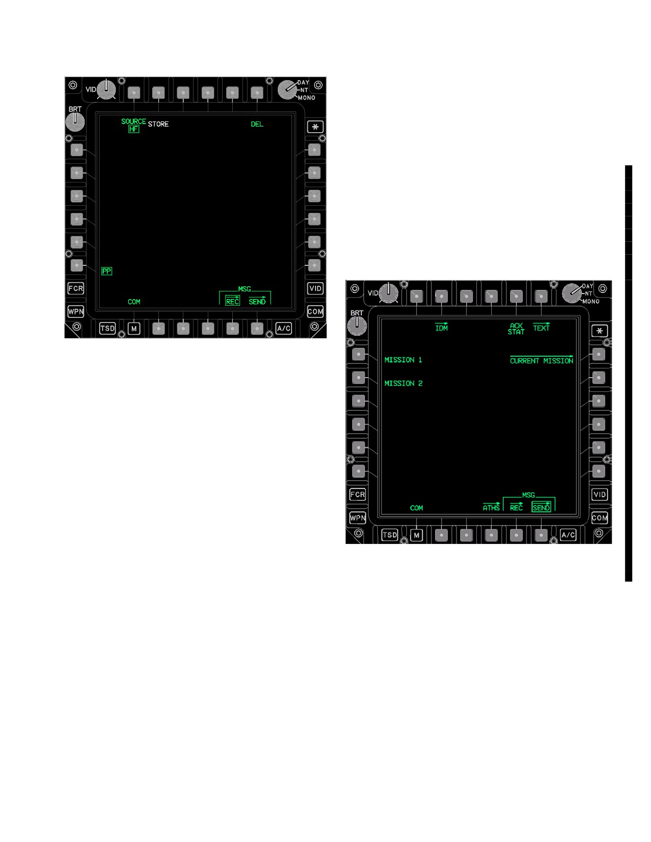
TM 1-1520-251-10
3A.35.16 DEL Button. Selecting this button deletes the
HF present position report. Selection of the HF PP DEL
button will prompt for a YES or NO confirmation to initiate
the deletion.
3A.36 MSG SEND PAGE
The MSG SEND page (fig 3A-43) provides controls to
send MISSION 1, MISSION 2, or ALL IDM/SOI data files
via the IDM to Longbow protocol team members. It also
provides access to the IDM page which is used to config-
ure the IDM and message parameter defaults. It also pro-
vides access to the CURRENT MISSION page which is
used for sending selected components of the current mis-
sion to team members.
LBA5078
Figure 3A-42. MSG REC Page (HF PP Selected)
3A.35.14 Free Text Message Window. The Free Text
Message Window (fig 3A-41) allows the crewmembers to
review Free Text messages received over the HF radio.
The MSG REC page contains the following unique but-
tons when SOURCE is HF and PP is selected:
• T2
STORE button
• T6
DEL button
3A.35.15 STORE Button. The HF PP STORE button
(fig 3A-42) provides the capability to store a present posi-
LBA5079
tion report received over the HF radio into the control
measures file, location 92.
Figure 3A-43. MSG SEND Page
Use or disclosure of this information is subject to the restriction(s) on the title page of this document.
Change 4
3A-47
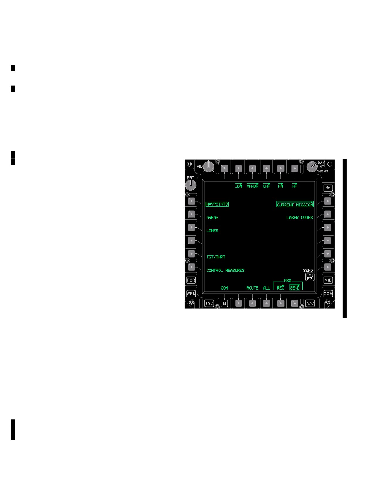
TM 1-1520-251-10
The MSG SEND page contains the following unique but-
3A.36.8 SEND Status Window. The SEND status win-
tons:
dow (fig 3A-47) provides a MPD display of the radio, IDM
protocol, and preset - net status that the IDM transmit se-
• T3
IDM button (TI message settings)
lect indicator for that crew station.
• T5
JVMF ACK button
3A.37 CURRENT MISSION PAGE
• T6
TEXT page button
The CURRENT MISSION button displays the CURRENT
• L1
MISSION 1 button
MISSION page (fig 3A-47). The CURRENT MISSION
• L2
MISSION 2 button
page provides the capability to individually select the type
• L3
ALL IDM/SOI buttons
of information to be sent over the IDM using Longbow
(AFAPD) protocol. Selection of the ALL button allows
• R1
CURRENT MISSION button
transmission of all current files. Once an item is selected,
• R6
SEND button
selecting the SEND button will initiate transmission over
the IDM.
3A.36.1 IDM Button. The IDM button displays the IDM-
page (para 3A.26).
3A.36.2 JVMF ACK Button. The JVMF ACK button
displays the JVMF ACK STATUS window.
3A.36.3 MISSION 1 (or 2) Buttons. The MISSION but-
tons provide the capability to transmit the MISSION 1 (or
2) files to selected Longbow protocol team members
upon the selection of the IDM SEND button.
3A.36.4 CURRENT MISSION Button. The CURRENT
MISSION button displays the LONGBOW protocol CUR-
RENT MISSION page.
3A.36.5 SEND Button. The SEND button is displayed
if the IDM is in the operate mode. The EUFD IDM transmit
select indicator is assigned to a compatible IDM protocol
net and a valid team member is in the net. The FREE
TEXT message is compatible with Longbow, Internet, and
Fire Support protocols while all other MSG SEND page
LBA5115A
messages are exclusive to Longbow protocol nets. The
selection of the SEND button will command the system to
Figure
3A-47.
CURRENT MISSION Page
transmit the selected files through the selected channel of
the IDM. The data is only sent to team members.
The CURRENT MISSION page contains the following
unique buttons:
3A.36.6 JVMF ACK STATUS Window. The JVMF
ACK STATUS window can be selectively opened using
• L1
WAYPOINTS button
the JVMF ACK button, and provides detailed status to the
• L2
AREAS button
operator of ACK, NAK, receiving platform operator inten-
• L3
LINES button
tions (e.g., WILCO, CANTCO) for the last JVMF message
• L4
ROUTE (CURRENT) button
sent, accepting JVMF messages issued via HF radio. Sta-
• L5
TGT/THRT button
tus is provided individually for all platforms to which a
• L6
CONTROL MEASURES button
message was sent.
• R2
LASER CODES button
• R6
SEND button
3A.36.7 TEXT Page Button. The TEXT page presents
the MPS TEXT MSG options and the FREE TEXT MSG
• B3
ROUTE button
editing display
• B4
ALL button
Use or disclosure of this information is subject to the restriction(s) on the title page of this document.
3A-48
Change 4
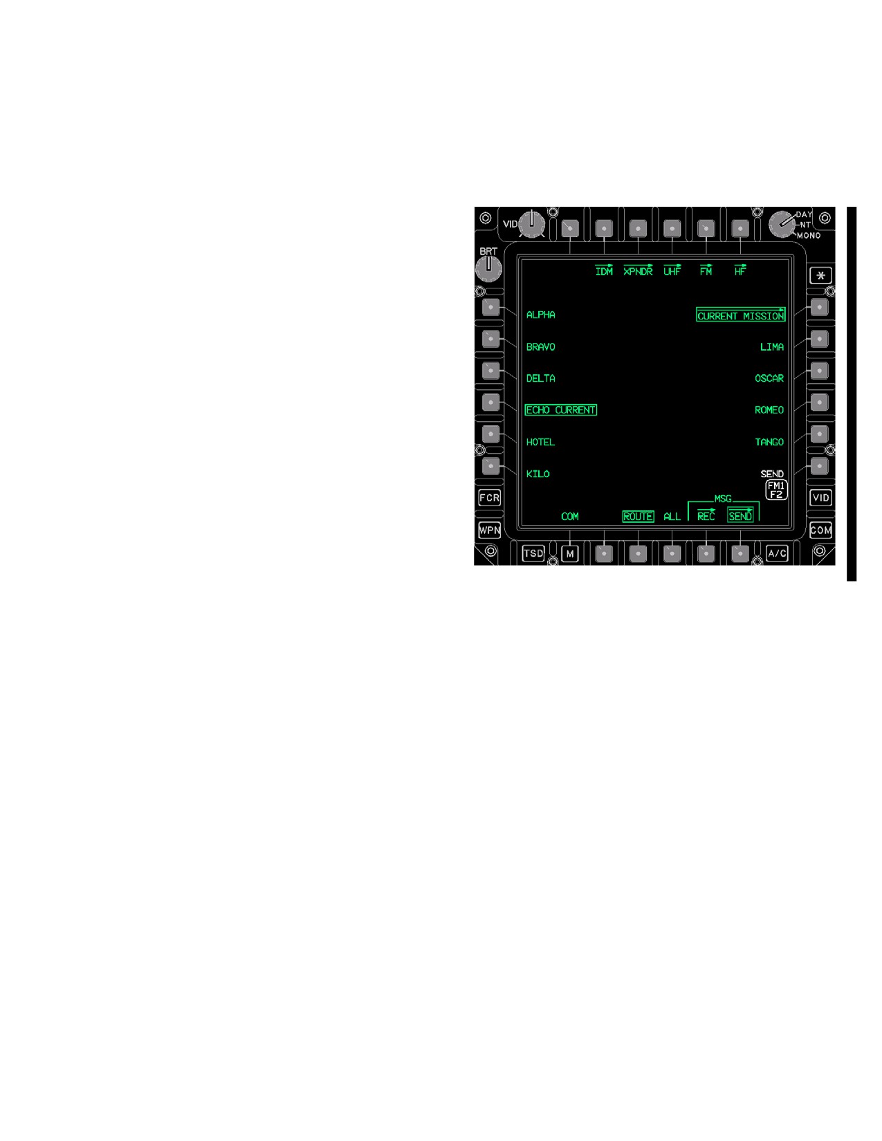
TM 1-1520-251-10
3A.37.1 WAYPOINTS Button. The WAYPOINTS but-
3A.38 CURRENT MISSION - ROUTE SELECTIONS
ton allows sending of the current waypoints file over the
IDM.
The ROUTE button (fig 3A-48) provides the capability to
select various routes for sending over the Longbow IDM
protocol.
3A.37.2 AREAS Button. The AREAS button allows
sending of the current engagement areas file over the
IDM.
3A.37.3 LINES Button. The LINES button allows
sending of the current phase lines file over the IDM.
3A.37.4 TGT/THRT Button. The TGT/THRT button al-
lows sending of the current target and threats file over the
IDM.
3A.37.5 CONTROL MEASURES Button. The CON-
TROL MEASURES button allows sending of the current
control measures file over the IDM.
3A.37.6 LASER CODES Button. The LASER CODES
button allows sending the current laser codes file over the
IDM.
3A.37.7 SEND Button. The SEND button is only dis-
LBA5116A
played if a valid CURRENT MISSION file is selected to be
sent. The selection of the SEND button will command the
Figure
3A-48.
CURRENT MISSION Page (ROUTE
system to transmit the selected files through the selected
Button Selected)
channel of the IDM. The selection of the SEND button will
command the system to transmit the selected files
through the selected LONGBOW protocol channel of the
The ROUTE button provides the following unique buttons:
IDM. The data is only sent to LONGBOW team members.
•
L1-L6
ROUTE buttons
• R2 - R5
ROUTE buttons
3A.37.8 ROUTE Button. The ROUTE button allows
sending of the current route file over the IDM. The ROUTE
• B4
ALL button
button presents all of the current routes files available for
3A.38.1 ROUTE Buttons. The ROUTE buttons allow
sending over the IDM (fig 3A-48).
selection of a single route file to send over the IDM.
3A.37.9 ALL Button. The ALL button allows sending
3A.38.2 ALL Button. The ALL button allows sending
of all current mission files over the IDM.
of all route files over the IDM.
Use or disclosure of this information is subject to the restriction(s) on the title page of this document.
Change 4
3A-49
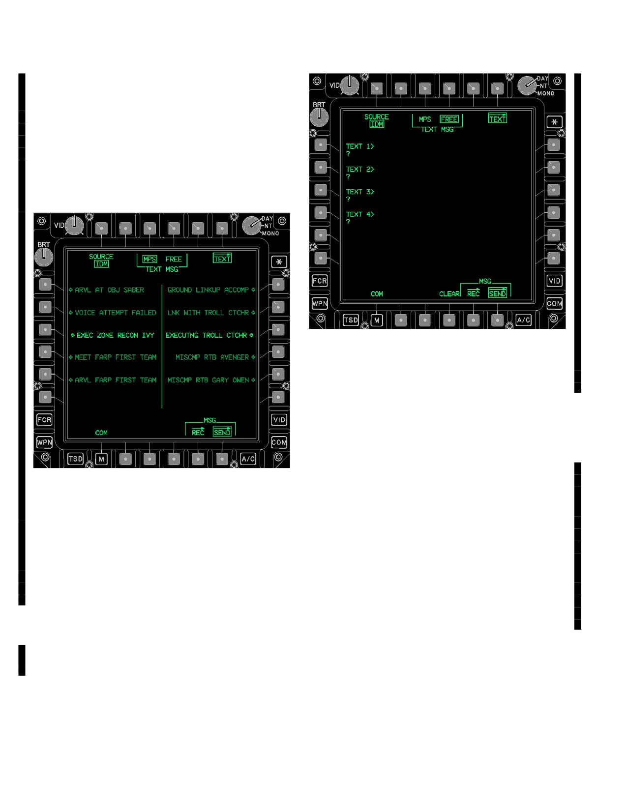
TM 1-1520-251-10
3A.39 TEXT PAGE
The TEXT page (fig 3A-49 and fig 3A-50) provides the capa-
bility to send a Mission Planning Station (MPS) non editable
text message or create a free text message for transmission
through the IDM using Longbow, Internet, or Fire Support
protocols or through the HF radio’s modem.
LBA5118A
Figure 3A-50. TEXT Page (Source IDM - FREE
TEXT)
3A.39.1 SOURCE Button. The SOURCE button
toggles between IDM or HF free text message controls.
3A.39.2 MPS TEXT Button. The MPS TEXT button dis-
LBA5117A
plays up to 10 non - editable premission planned text mes-
sages that may be selected and sent to any JVMF entity.
3A.39.3 FREE TEXT Button. The FREE TEXT button
Figure 3A-49. TEXT Page (Source IDM - MPS TEXT)
displays the editable FREE TEXT format used to develop
free text messages that may be sent via Longbow
(AFAPD) or JVFM.
The TEXT page contains the following unique buttons
when SOURCE is IDM and FREE TEXT is selected (refer
3A.39.4 IDM FREE TEXT Buttons. Each IDM FREE
to fig 3A-50):
TEXT (1-4) button provides the capability to load four
44-character messages into the system for transmission
by the IDM radio.
• T1
SOURCE button
• T3
MPS TEXT button
3A.39.3 SEND Button. The SEND button transmits the
IDM TEXT message through the selected channel of the
• T4
FREE TEXT button
IDM or through the HF’s modem. With SOURCE to IDM,
• L1-L4
IDM TEXT (1-4) buttons
the data is only sent to team members.
• R6
SEND button
3A.39.4 CLEAR Button. The CLEAR button clears the
• B4
CLEAR button
data contained in the IDM TEXT buttons.
Use or disclosure of this information is subject to the restriction(s) on the title page of this document.
3A-50
Change 4
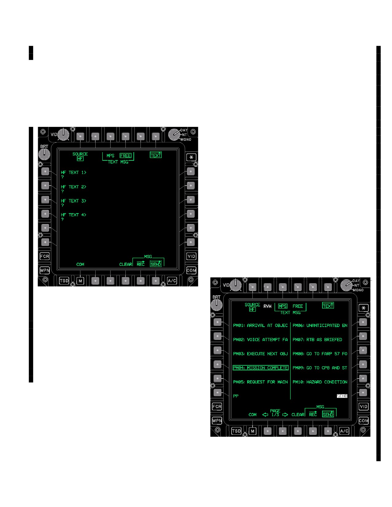
TM 1-1520-251-10
The TEXT page contains the following unique buttons when
The TEXT page contains the following unique buttons
SOURCE is HF and FREE TEXT is selected (fig 3A-51):
when SOURCE is IDM and MPS TEXT is selected (refer
to fig 3A-49):
• L1-L4
HF TEXT (1-4) buttons
• T1
SOURCE button
• R6
SEND button
• L1-L5
MPS IDM MESSAGE (1-5) buttons
• R1-R5
MPS IDM MESSAGE (6-10) buttons
• B4
CLEAR or ABORT button
• R6
SEND button
3A.40 MPS IDM MESSAGE Buttons. The MPS IDM
MESSAGE buttons provide the capability to review an
MPS pre - planned message and select it for
transmission by the IDM
The TEXT page contains the following unique buttons
when SOURCE is HF and MPS TEXT is selected (refer to
fig 3A-52):
• T1
SOURCE button
• T2
RVW button
• L1-L5
PM (1-5) buttons
• L6
PP button
• R1-R5
PM (6-10) buttons
• R6
SEND button
• B2 - B3
PAGE LEFT/RIGHT buttons
• B4
CLEAR or ABORT button
LBA5491
Figure 3A-51. TEXT Page (Source HF - FREE
TEXT)
3A.39.5 HF TEXT Buttons. Each HF TEXT (1-4) but-
ton provides the capability to load four 44-character mes-
sages into the system for transmission by the HF radio.
3A.39.6 SEND Button. The SEND button transmits the
HF TEXT message through the HF radio’s modem.
3A.39.7 CLEAR/ABORT Buttons. The CLEAR button
LBA5119
clears the data contained in the HF TEXT buttons. The
ABORT button is displayed while the HF TEXT is being
sent, in order to allow the crew to abort the transmission.
Figure 3A-52. TEXT Page (Source HF - MPS TEXT)
Use or disclosure of this information is subject to the restriction(s) on the title page of this document.
Change 4
3A-51
TM 1-1520-251-10
3A.40.1 SOURCE Button. The SOURCE button
3A.40.4 PP Button. The PP button provides the capa-
toggles between IDM or HF free text message controls.
bility to send the ownship present position over the HF ra-
dio’s modem.
3A.40.2 RVW Button. The RVW button allows the op-
erator to review the MPS pre - planned messages.
3A.40.3 PM Buttons. The PM buttons allow the opera-
3A.40.5 PAGE LEFT/RIGHT Buttons. The PAGE
tor to select an MPS pre - planned message for review or
LEFT/RIGHT buttons allows the operator to scroll to the
transmission by the HF radio.
previous or next page of 10 preplanned HF messages.
Use or disclosure of this information is subject to the restriction(s) on the title page of this document.
3A-52
Change 4
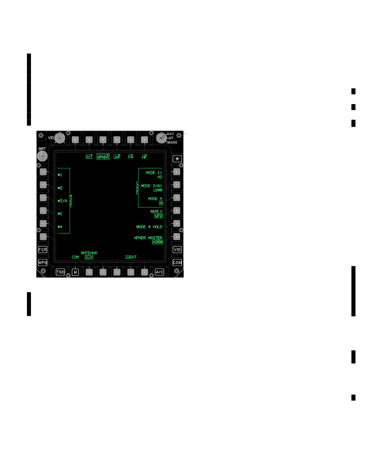
TM 1-1520-251-10
NOTE
• R5
MODE 4 HOLD button
Due to the APX-118 hardware and software
• R6
XPNDR MASTER button
fielding plan, it is possible to have either an
• B2
ANTENNA button
APX - 100 or APX - 118 installed. See para-
• B5
IDENT button
graph 3A.42 for APX-100 and paragraph
3A.42A for APX-118.
3A.42.2 MODE 1 Button. The MODE 1 button enables/
disables MODE 1 replies.
3A.42 XPNDR PAGE (APX - 100)
3A.42.3 MODE 2 Button. The MODE 2 button enables/
The XPNDR page for the APX - 100 (fig 3A-57) provides
disables MODE 2 replies.
the capability to control the APX - 100 transponder func-
3A.42.4 MODE 3/A Button. The MODE 3/A button en-
tions.
ables/disables Mode 3/A replies. When MODE 3/A button is
selected OFF, the MODE C button is automatically turned
OFF.
3A.42.5 MODE C Button. The MODE C button enables/
disables the MODE C transmission. When MODE C button is
selected ON, the MODE 3/A button is automatically turned
ON.
3A.42.6 MODE 4 Button. The MODE 4 button enables/
disables MODE 4. The MODE 4 Code data field on the
EUFD (para 3A.16) is updated when the mode has been
changed.
3A.42.7 CODE MODE 1 Button. The CODE MODE 1
button provides the capability to change the MODE 1 code.
3A.42.8 CODE MODE 3/A Button. The CODE MODE
3/A button provides the capability to change the MODE 3/A
MODE 2 codes.
NOTE
• The MODE 2 code must be manually en-
tered on the face of the APX-100.
• If an APX-118 is installed, but the
APX - 100 MPD controls are present due
LBA5125
to the APX - 118 hardware and software
fielding plan, the MODE 2 Code entry
Figure 3A-57. XPNDR Page (APX - 100)
procedure must be performed as de-
3A.42.1 XPNDR Page Button. The XPNDR page con-
scribed below.
tains the following unique buttons:
1. Select MODE 3/A button and enter “2222”.
• L1
MODE 1 button
NOTE
• L2
MODE 2 button
If the assigned mode 2 code is not entered
within 15 seconds, 2222 will be displayed as
• L3
MODE 3/A button
the current MODE 3/A code.
• L4
MODE C button
2. Select the MODE 3/A button again and enter the
• L5
MODE 4 button
MODE 2 Code.
• R1
CODE Mode 1 button
3A.42.9 CODE MODE 4 Button. The CODE MODE 4
button toggles between XPNDR code MODE 4 A and B. The
• R2
CODE Mode 3/A button
code Mode 4 data field is updated when the code has been
• R3
CODE Mode 4 button
changed. When the APX-100 is installed, the CODE MODE
• R4
REPLY button
4 button is only displayed if the KIT-1C computer is installed.
Use or disclosure of this information is subject to the restriction(s) on the title page of this document.
Change 4
3A-53
TM 1-1520-251-10
3A.42.10 REPLY Button.The REPLY button controls the
aircraft is in the air (squat switch disabled). The MODE 4
feedback the crew will receive when the XPNDR fails to reply
HOLD button is only displayed with the Kit-1C comsec de-
(i.e MODE 4 disabled) or unsuccessfully replies (i.e. no codes
vice is installed.
loaded or wrong codes, A or B, selected) to a MODE 4
3A.42.12 XPNDR MASTER Button. The XPNDR
interrogation. In either case, if the REPLY button is set to
MASTER button changes the transponder mode between
UFD/AUDIO, the XPNDR will generate the IFF tone to alert
STBY (Standby) and NORM (Normal). The XPNDR will
the crew of a failed interrogation and display the mode 4 advi-
only repond to interrogations when in NORM.
sory on the EUFD. If the REPLY button is set to UFD, then
3A.42.13 ANTENNA Button. The ANTENNA multi -
only the EUFD advisory indication is used. If set to OFF, then
state button allows the crew to control which antenna the
no indication is used.
xpndr will reply from when interrogated (Top, Bot or Diver-
3A.42.11 MODE 4 HOLD Button. Selecting the MODE 4
sity).
HOLD button causes the Mode 4 Codes to be saved to
3A.42.14 IDENT Button. The IDENT button provides
xpndr non-volitile memory so the Mode 4 Codes will not be
the capability to command the XPNDR to ident. When se-
erased when the aircaft is on the ground and power is re-
lected, the ident mode is enabled for 15 - 30 seconds for
moved from the XPNDR. To successfully save the Mode 4
modes 1, 2, and 3/A (if enabled). The IDENT button will
Codes, the MODE 4 HOLD button must be pressed while the
not be displayed when the XPNDR is in STBY.
Use or disclosure of this information is subject to the restriction(s) on the title page of this document.
3A-54
Change 4
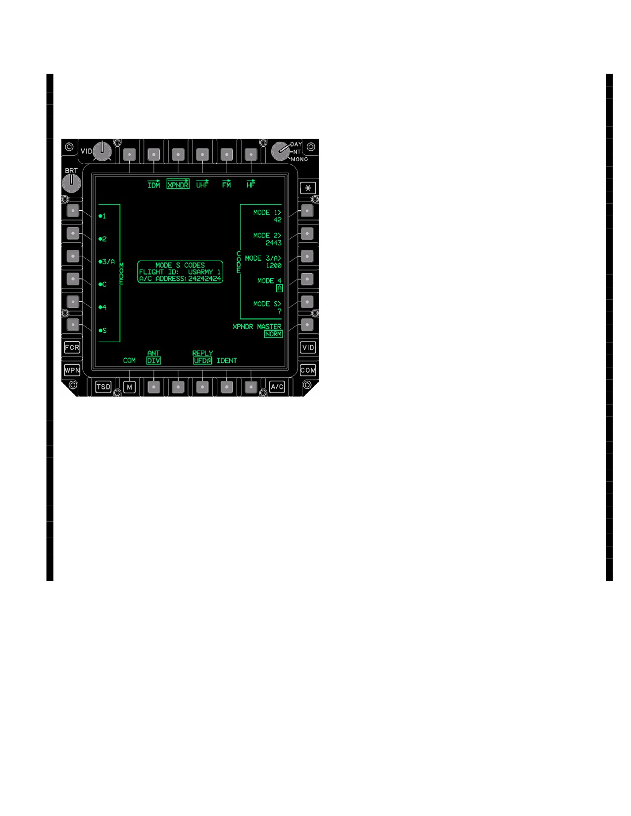
TM 1-1520-251-10
3A.42A XPNDR PAGE (APX - 118)
3A.42A.2 MODE S Button The MODE S button enables/di-
ables MODE S replies. The mode S enabled/disabled field on
The XPNDR page for the APX - 118 (fig 3A-57A) provides
the EUFD is updated to reflect the button’s current mode
the capability to control the APX - 100 transponder func-
(para 3A.16).
tions.
3A.42A.3 CODE MODE 2 Button The CODE MODE 2 but-
ton provides the capability to change the MODE 2 Code.
3A.42A.4 CODE MODE 3/A Button. The CODE MODE
3/A button provides the capability to change the MODE 3/A
code.
3A.42A.5 CODE MODE 4 Button. The CODE MODE 4
button toggles between XPNDR code MODE 4 A and B. The
code Mode 4 data field is updated when the code has been
changed.
NOTE
The APX-118 does not allow disable of the
Mode 4 EUFD advisory message via the RE-
PLY button. The only way to disable the advi-
sory message is to turn Mode 4 off using the
Mode 4 on/off button.
3A.42A.6 REPLY Button. The REPLY button controls the
feedback the crew will receive when the XPNDR fails to reply
(i.e MODE 4 disabled) or unsuccessfully replies (i.e. no codes
loaded or wrong codes, A or B, selected) to a MODE 4
interrogation. In either case, if the REPLY button is set to
LBA5407
UFD(music note), the XPNDR will generate the IFF tone to
alert the crew of a failed interrogation and display the mode 4
Figure
3A-57A.
XPNDR Page (APX - 118)
advisory on the EUFD. If the REPLY button is set to UFD,
then only the EUFD advisory indication is used. If set to OFF,
3A.42A.1 XPNDR Page Button. The XPNDR page
then no indication is used.
contains the following unique buttons:
3A.42A.7 ANTENNA Button. The ANTENNA multi -
• L6
MODE S button
state button allows the crew to control which antenna the
• R2
CODE Mode 2 button
XPNDR will reply from when interrogated (Top, Bot or
• R3
CODE Mode 3/A button
Div). The APX - 118 will only be moded to Top or Bot for
about 60 seconds before returning to Div
• R4
CODE Mode 4 button
3A.42A.8 MODE S Status Window. The MODE S Sta-
• R5
CODE Mode S button
tus Window indicates to the crew the current values of the
• B2
ANTENNA button
MODE S Codes for both the Flight ID and the Aircraft Ad-
• B4
REPLY button
dress.
Use or disclosure of this information is subject to the restriction(s) on the title page of this document.
Change 4
3A-55
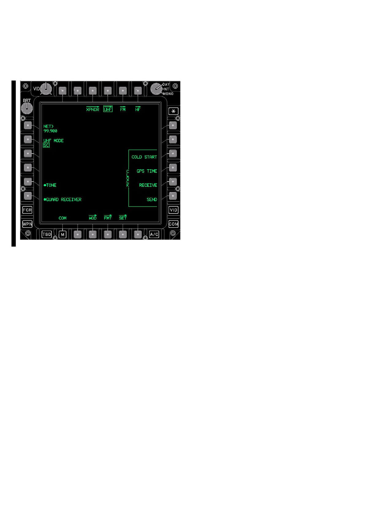
TM 1-1520-251-10
3A.43 UHF PAGE
QUICK net numbers allow multiple station pairs to operate si-
multaneously using the same TOD (Time of Day) and WOD
The UHF page (fig 3A-58) provides specific controls for the
(Word of Day) without interference.
ARC-164 UHF radio.
3A.43.3 TONE Button. The TONE button allows the crew
to enable/disable the HAVE QUICK tones in the UHF radio.
3A.43.4 GUARD RECEIVER Button. The GUARD RE-
CEIVER button enables/disables the UHF radio’s monitoring
of the guard frequency.
3A.43.5 CAL DAY Button. The CAL DAY button provides
the capability to change the Calendar Day in the UHF radio.
The Calendar Day is the internal date utilized by the UHF ra-
dio. When the Calendar Day and a WOD match in the UHF
radio, the associated segments become active, allowing
HAVE QUICK communications.
3A.43.6 COLD START Button. The COLD START button
activates the Emergency Cold Start of the UHF radio’s inter-
nal clock. This will reset and start the UHF radio’s internal
clock at zero hundred hours. The COLD START button is
used when there is no other TOD available and a reference
time is required. The COLD START button is barriered when
the UHF radio is in HAVE QUICK mode.
3A.43.7 GPS TIME Button. The GPS TIME button causes
the current time from the EGI to be loaded into the UHF ra-
dio’s internal clock. The GPS TIME button is barriered when
the UHF radio is in HAVE QUICK mode.
LBA5126A
NOTE
Figure
3A-58.
UHF Page
Notify the other crewmember when initiating
The UHF page contains the following unique buttons:
the UHF RECEIVE button, to prevent inad-
vertent termination of reception.
• L1
NET button
3A.43.8 RECEIVE TIME Button. The RECEIVE TIME
• L2
UHF MODE button
button configures the UHF radio to TOD receive. A tone is
• L5
TONE button
generated upon successful reception of time. If TOD is not
• L6
GUARD RECEIVER button
received within 60 seconds, the UHF radio will exit the re-
• R2
CAL DAY button
ceive mode.
• R3
COLD START button
3A.43.9 SEND TIME Button. The SEND TIME button
• R4
GPS TIME button
transmits the TOD. A tone in the headset sounds when the
• R5
RECEIVE TIME button
TOD is transmitted.
• R6
SEND TIME button
• B3
WOD page button
3A.43.10 WOD Page Button. The WOD button displays
• B4
FMT page button
the UHF WOD page (para 3A.44).
• B5
SET page button
3A.43.11 FMT Page Button. The FMT button displays the
3A.43.1 UHF MODE Button. The UHF MODE button pro-
FMT page (para 3A.45).
vides the capability to control the mode of the UHF radio. Op-
3A.43.12 SET Page Button. The SET page button dis-
tions are SC (Single Channel) and HQ (HAVE QUICK).
plays the SET page. The page contains the UHF CRYPTO
3A.43.2 NET Button. The NET button allows the crew to
button and UHF CNV button which are used to configure the
enter a HAVE QUICK net number into the UHF radio. HAVE
Crypto device (para 3A.46).
Use or disclosure of this information is subject to the restriction(s) on the title page of this document.
3A-56
Change 4
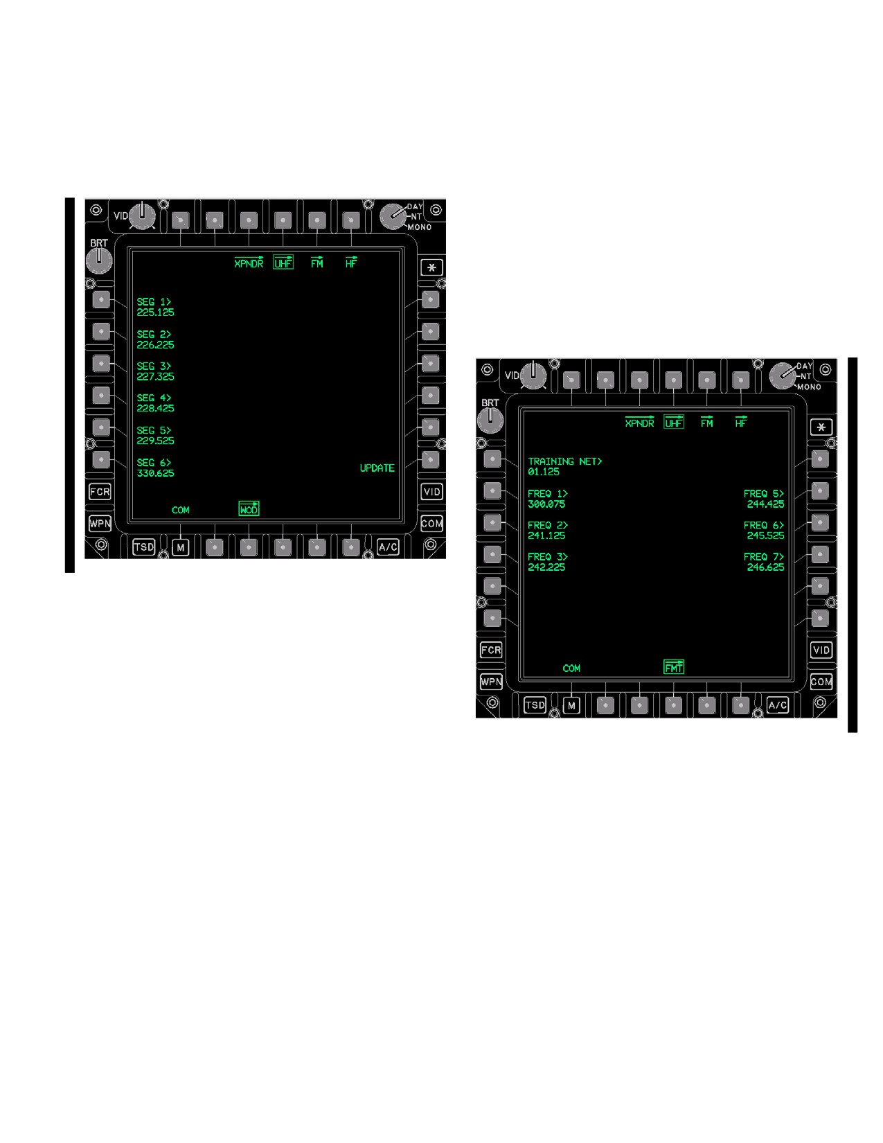
TM 1-1520-251-10
3A.44 UHF WOD PAGE
3A.44.3 SEGment Buttons. Upon entry to the UHF
WOD page the SEG buttons are zeroized. The SEG but-
The UHF WOD page (fig 3A-59) allows the crew to manu-
tons allow entry of up to six WOD segments for update
ally enter and load WOD and WOD Segments into the
into the UHF radio. At least one WOD segment must be
UHF radio.
loaded into the UHF radio for HAVE QUICK operation.
3A.44.4 CLEAR Button. The CLEAR button provides
the capability to clear (i.e. zeroize) the data in the DAY
and SEG buttons.
3A.45 UHF FMT PAGE
The UHF FMT page (fig 3A-60) contains the HAVE
QUICK Training Frequencies which can be entered or
modified and then loaded into the UHF radio.
LBA5127A
Figure 3A-59. UHF WOD Page
The UHF WOD page contains the following unique buttons:
• R6
UPDATE button
• L1 - L6
SEG (1 - 6) (segment) buttons
• B4
CLEAR button
3A.44.1 UHF WOD DAY Button. Upon entry to the
LBA5128A
UHF WOD page the UHF WOD DAY button is zeroized.
Figure 3A-60. UHF FMT Page
The UHF WOD DAY button allows entry of a WOD for a
new set of WOD Segments. When the Calendar Day and
a WOD match in the UHF radio, the associated segments
The UHF FMT page contains the following unique buttons:
become active, allowing HAVE QUICK communications.
• L2 - L5
FREQ buttons
3A.44.2 UPDATE Button. The UPDATE button loads
• L6
UPDATE button
the DAY and SEG data into the UHF radio. Upon a valid
• R2 - R5
FREQ buttons
update into the UHF radio, a tone is generated and the
• B2
PAGE Back button
WOD STATUS window is updated.
•
B3
PAGE Forward button
NOTE
3A.45.1 FREQ Buttons. The FREQ buttons provide
Deselecting the WOD page prior to selec-
the capability to enter or modify the 16 HAVE QUICK
tion of the update button will remove the
Training Frequencies.
segments from the segment buttons and will
replace them with question marks. Entry of
3A.45.2 UPDATE Button. The UPDATE button loads
segments in one crewstation cannot be
the UHF FMT FREQ data into the UHF radio. Upon a valid
monitored in the opposite crewstation.
update into the UHF radio, a tone is generated.
Use or disclosure of this information is subject to the restriction(s) on the title page of this document.
Change 4
3A-57
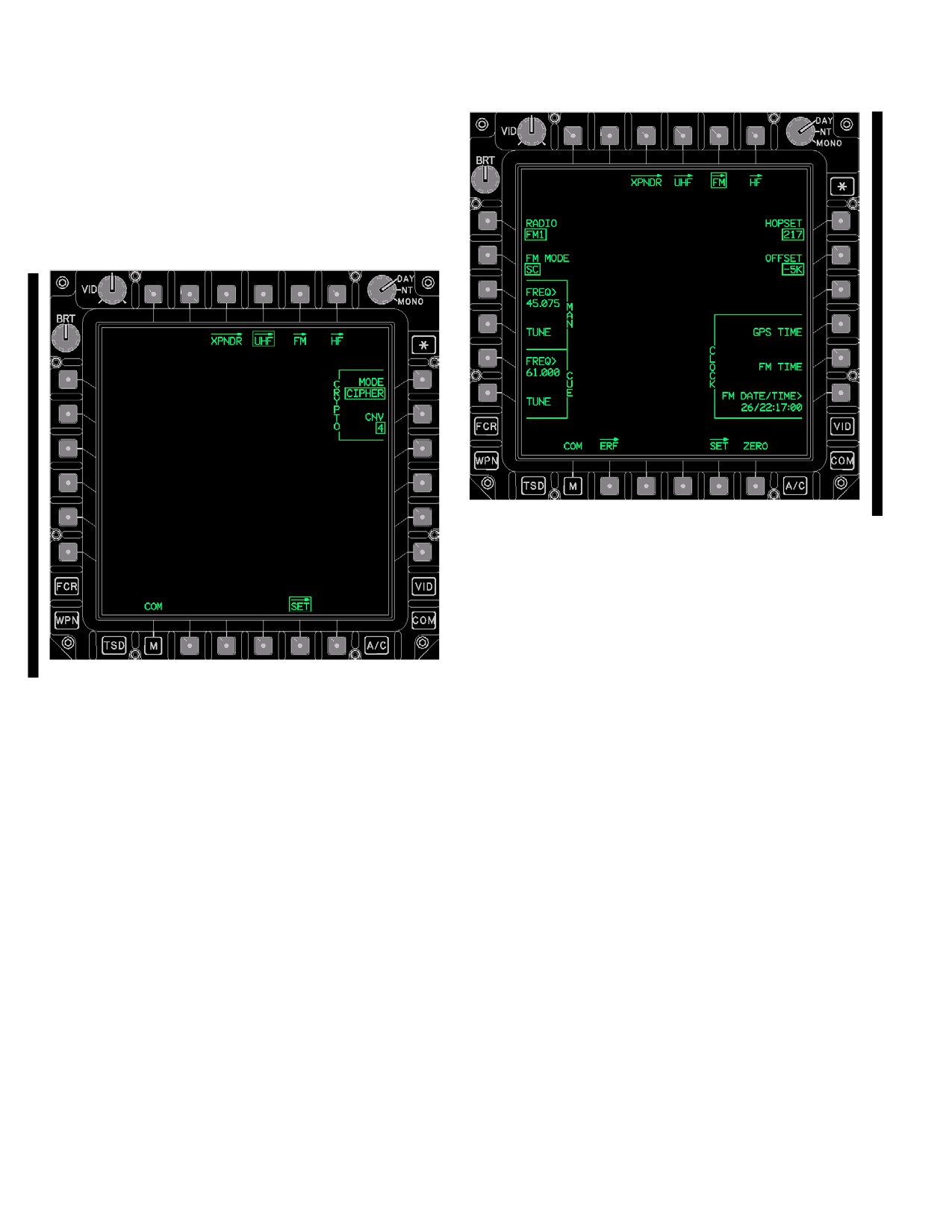
TM 1-1520-251-10
3A.45.3 PAGE Back and PAGE Forward Buttons. Al-
lows selection between two pages of HAVE QUICK Train-
ing Frequencies.
3A.46 UHF SET PAGE
The UHF SET page (fig 3A-61) contains the CRYPTO
MODE and CRYPTO CNV buttons for the UHF radio.
LBA5130A
Figure 3A-62. FM Page - SC MODE
The FM page contains the following unique buttons:
• L1
RADIO button
• L2
FM 1 MODE or FM 2 MODE button
LBA5129A
• L3
MAN FREQ button
• L4
MAN TUNE button
Figure 3A-61. UHF SET Page
• L5
CUE FREQ button
• L6
CUE TUNE button
The UHF SET page contains the following unique buttons:
• R1
HOPSET button
• L2
CRYPTO MODE button
• R2
OFFSET button
• L6
CRYPTO CNV button
• R3
LATE NET button
3A.46.1 CRYPTO MODE Button. The CRYPTO
• R4
CLOCK GPS TIME button
MODE button controls the operation of the KY - 58. The
• R5
CLOCK FM TIME button
button provides options of CIPHER, PLAIN, and RE-
• R6
CLOCK FM DATE/TIME button
CEIVE.
•
B2
ERF page button
3A.46.2 CRYPTO CNV Button. The CRYPTO CNV
• B5
SET page button
button provides the capability to change the UHF crypto
• B6
ZERO button
net variable with options of 1 through 6.
3A.47.1 FM RADIO Button. The RADIO button pro-
3A.47 FM PAGE
vides the capability to toggle the display between the FM1
and the FM2 radio controls.
The FM page (fig 3A-62) provides the capability to control
the FM radios and their FH modes. The radio control but-
3A.47.2 FM MODE Button. The FM Mode button pro-
tons on the FM page are only displayed if the radio is
vides the capability to control the mode of the selected ra-
installed.
dio. The button provides options of FM SC, FM FH, and
Use or disclosure of this information is subject to the restriction(s) on the title page of this document.
3A-58
Change 4
TM 1-1520-251-10
FM FH/M (Frequency Hopping/Master). SC mode allows
used if the two net TODs are within 1 minute (plus/minus)
access to the ERF Page. FH mode allows access to the
of each other. This button is only displayed when the SINC
ERF Receive Page. FH/M mode allows access to the ERF
mode is FH.
Send Page.
3A.47.10 CLOCK GPS TIME Button. The GPS TIME
3A.47.3 MAN FREQ Button. The MAN FREQ button
button causes the current time from the EGI to be loaded
provides the capability to change the Manual frequency of
into the radio and extracts that time from the selected ra-
the selected radio.
dio and displays the data within the DATE/TIME button.
3A.47.4 MAN TUNE Button. The MAN TUNE button
3A.47.11 CLOCK FM TIME Button. The FM TIME but-
provides the capability to tune the radio to the frequency
ton extracts the current time from the selected radio and
that is displayed within the MAN FREQ window.
displays the data within the DATE/TIME button.
3A.47.5 CUE FREQ Button. The CUE FREQ button
3A.47.12 CLOCK FM DATE/TIME Button. The FM
provides the capability to change the Cue frequency of the
DATE/TIME button provides the capability to change the
selected radio.
date and time currently loaded into the selected radio.
This data is displayed for 1 minute, then is considered
3A.47.6 CUE TUNE Button. The CUE TUNE button
stale.
provides the capability to tune the radio to the frequency
that is displayed within the CUE FREQ window.
3A.47.13 ERF Page Button. Selecting the ERF page
button will display the ERF page. The ERF page provides
3A.47.7 HOPSET Button. The HOPSET button pro-
the operator the capability to manage hopsets and lockout
vides seven options that include the six HOPSET buttons
sets (para 3A.48).
and the MAN button. The hopset ID selected determines
the radio FH characteristics (hopping rate, frequencies,
3A.47.14 SET Page Button. The SET page button dis-
and frequency order).
plays the FM SET page, which contains the POWER but-
ton, the CRYPTO button and the CNV button.
3A.47.8 OFFSET Button. The OFFSET button pro-
vides the capability to control the offset ( - 10K, - 5K, 0,
+5K, +10K) from the single channel FM frequency. The
3A.47.15 ZERO Button. The ZERO button provides
OFFSET button is only displayed when the FM1 MODE or
the capability to zeroize the FM radio.
FM 2 MODE is set to SC.
3A.47.16 ERF RECEIVE Window. The white ERF RE-
3A.47.9 LATE NET Button. The LATE NET button is
CEIVE window will display on the FM ERF, and ERF
used to synchronize to an operational net whose TOD is
SEND pages whenever the ERF RECEIVE button on the
not within the 4 second (plus/minus) frequency hopping
ERF RECEIVE page is left selected for receipt of multiple
communication window. The late net function may only be
ERFs.
Use or disclosure of this information is subject to the restriction(s) on the title page of this document.
Change 2
3A-59
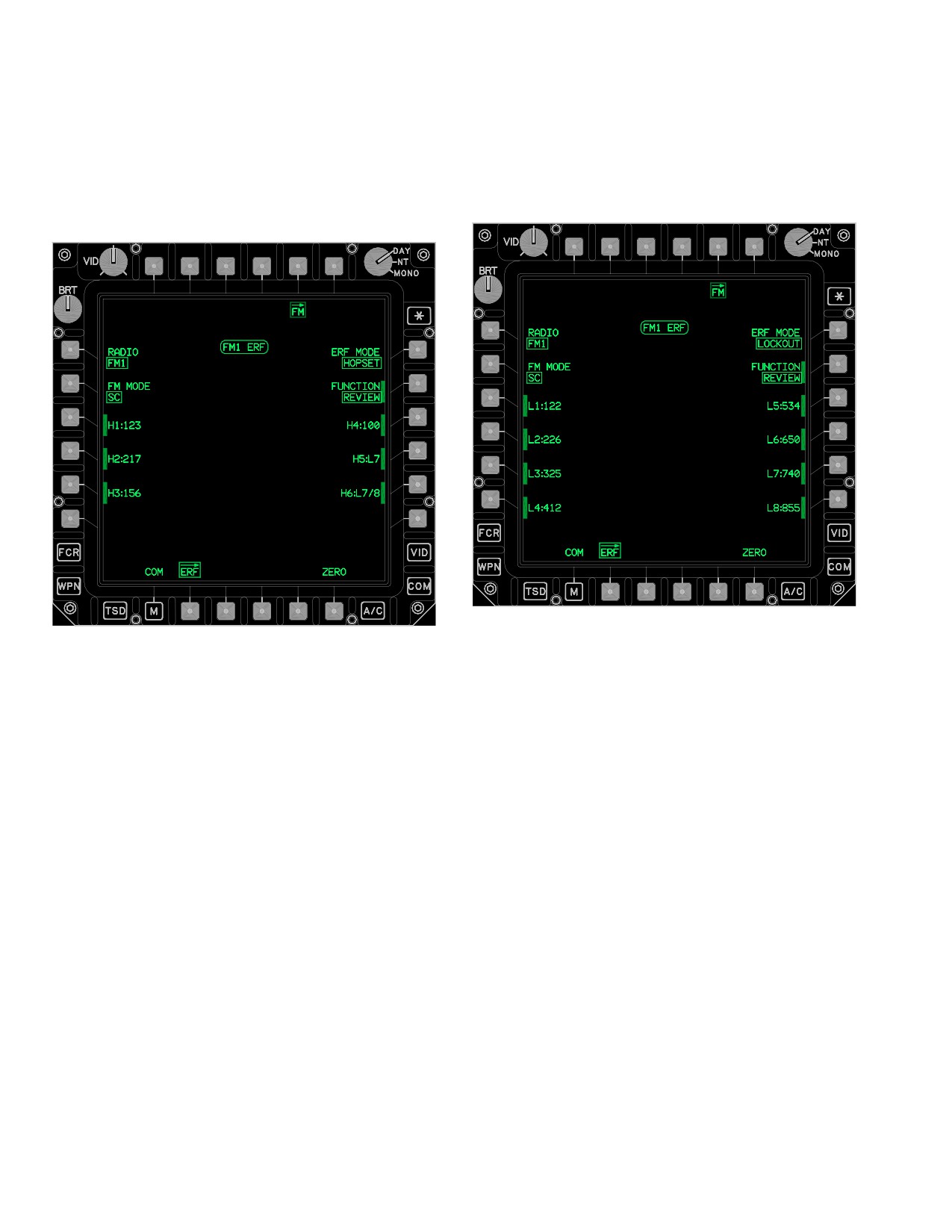
TM 1-1520-251-10
3A.48 FM ERF PAGE
• R2
FUNCTION button
• R3-R6
Hopset/Lockout buttons
The FM ERF page (figs 3A-63 and 3A-64 ) provides the
• B4
CLEAR button
capability to manage Hopsets and Lockout sets data. The
FM ERF page incorporates three distinct modes of opera-
• B6
ZERO button
tion (para 3A.48.5).
LBA5136
LBA5135
Figure 3A-64. FM ERF Page - Lockout Mode
Figure 3A-63. FM ERF Page - Hopset Mode
3A.48.1 RECEIVE Button. The RECEIVE button (figs
The ERF page contains the following unique buttons:
3A-65 and 3A-66) provides the capability to command the
radio to the ERF receive mode. The radio remains in the
• T3
RECEIVE OR SEND button
ERF receive mode to receive multiple ERFs for 5 minutes
• T4
STORE button
unless the RECEIVE button is manually deselected or au-
• L1
RADIO mode button
tomatically deselected when a confirmed CLEAR is per-
formed. When a hopset or lockout set is received, this but-
• L2
FM MODE button
ton will be barriered until the Hopset or Lockout is either
• L3-L6
Hopset/Lockout buttons
cleared or stored (fig 3A-65). The RECEIVE button is only
• R1
ERF MODE button
available when the FM MODE button set to FH.
Use or disclosure of this information is subject to the restriction(s) on the title page of this document.
3A-60
Change 2
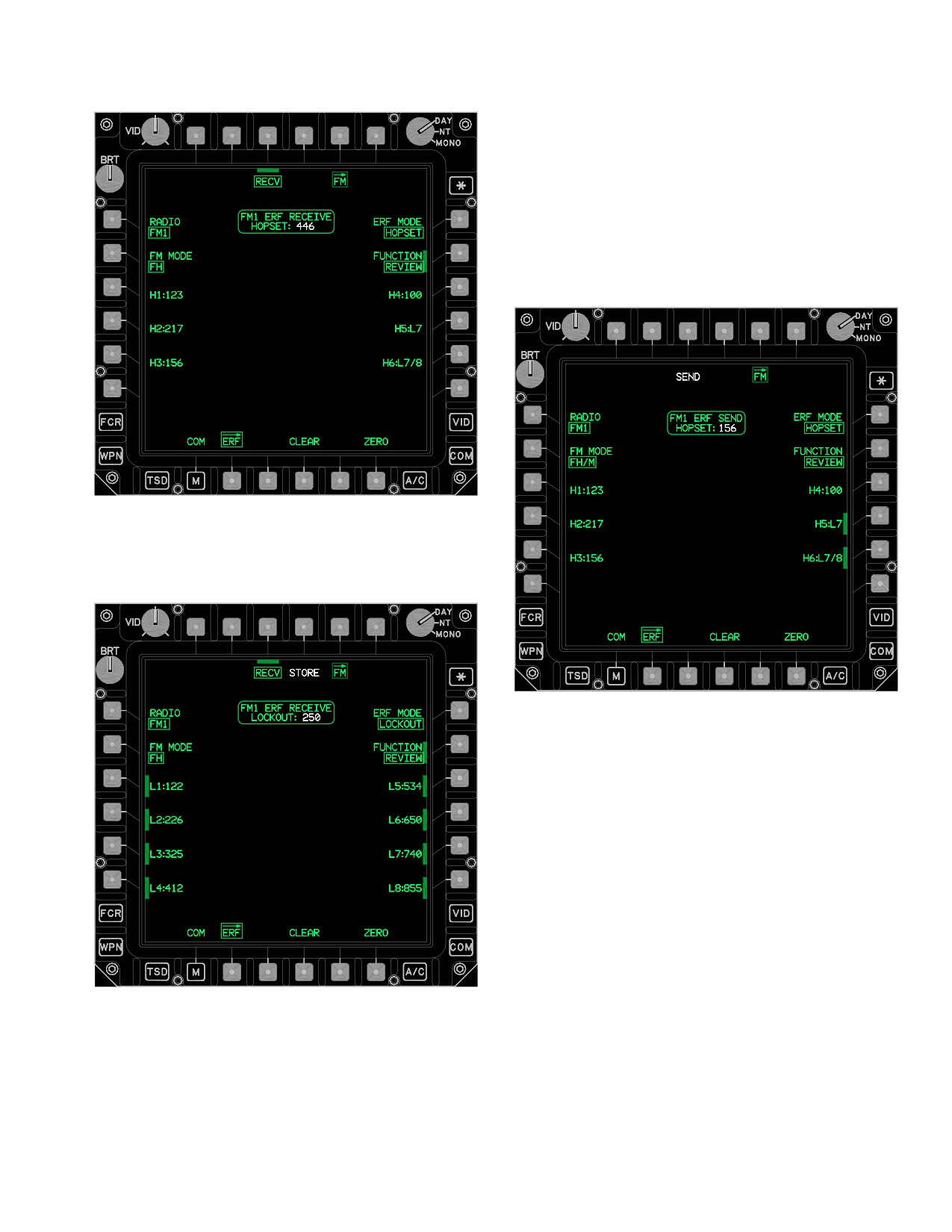
TM 1-1520-251-10
3A.48.2 SEND Button. The SEND button (fig 3A-67)
commands the radio to transmit the hopset or lockout ID
displayed within the FM ERF status window. This button is
only displayed when an H or L button is selected while the
FUNCTION button is set to REVIEW. The SEND button is
displayed in white and is only available when the FM
MODE button set to FH/M.
LBA5137
Figure 3A-65. FM ERF RECEIVE Page - Hopset
Received
LBA5139
Figure 3A-67. ERF Page - FH/M Mode, ERF SEND
HOPSET Displayed
3A.48.3 STORE Button. The STORE button is only
displayed when a valid lockout has been received into the
holding memory buffer as displayed in the FM ERF status
window. The STORE button is displayed in white and is
only available when the FM MODE button set to FH.
LBA5138
3A.48.4 RADIO Button. The RADIO button configures
Figure 3A-66. FM ERF RECEIVE Page - Lockout
the FM ERF page to present controls for either the FM1 or
Received
FM2 radio.
Use or disclosure of this information is subject to the restriction(s) on the title page of this document.
Change 2
3A-61
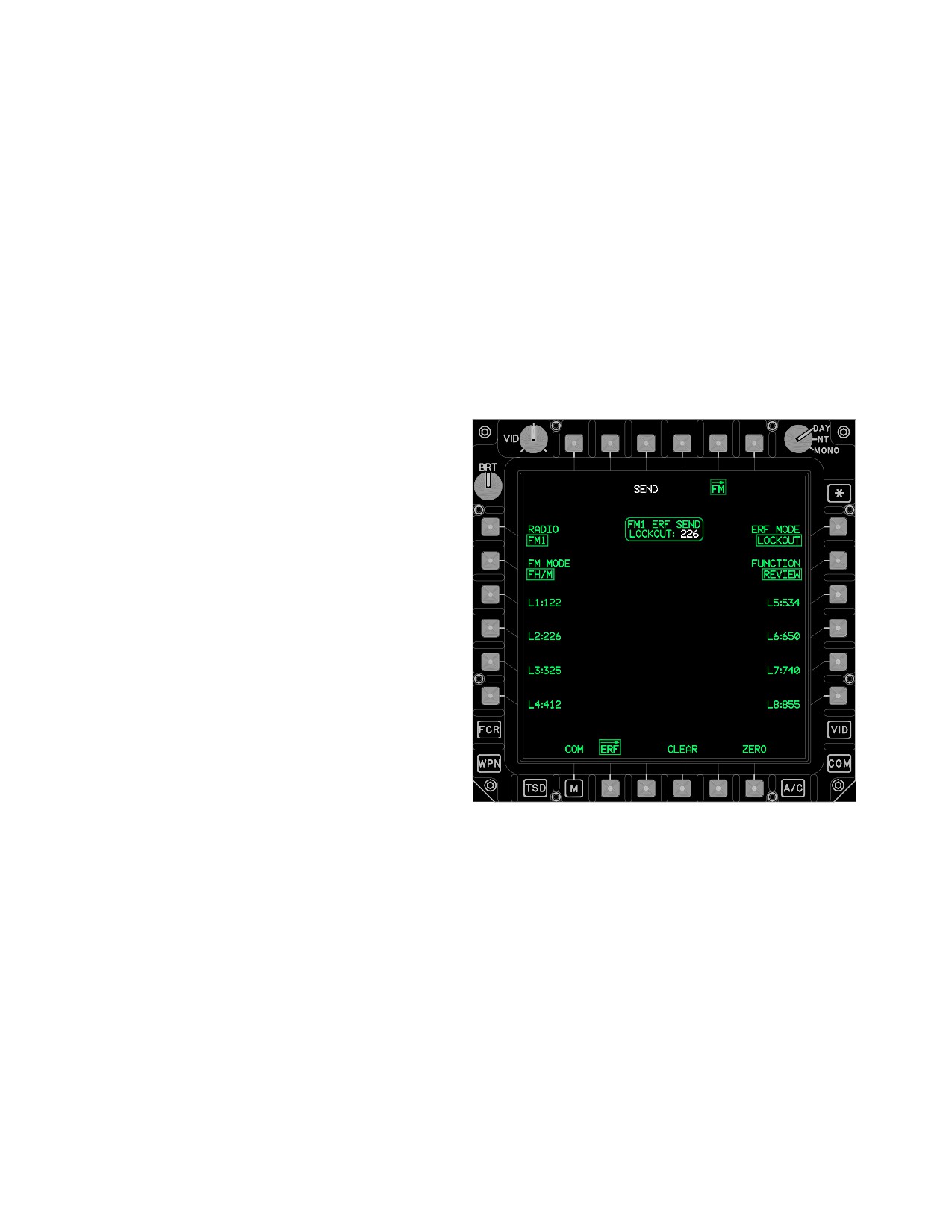
TM 1-1520-251-10
3A.48.5 FM MODE Button. The FM MODE button con-
b. FM MODE FH/M. When sending the ERF HOP-
trols the ECCM mode of the selected FM radio:
SET buttons (fig 3A-67) provide the capability to select a
hopset to be transmitted through the ERF process. The
• Single Channel
current hopset to be sent is displayed in the SEND HOP-
• Frequency Hopping
SET window and an intermittent beep will be heard until
the hopset is sent or cleared.
• Frequency Hopping Master
3A.48.9 Lockout (L) Buttons.
a. In Single Channel operation, the FM radio trans-
mits and receives on a single frequency. Although not op-
a. FM MODE FH. The L buttons are only selectable
erating in an ECCM mode, the radio can minimize interfer-
when deleting Lockouts.
ence with the use of frequency offsets. When operating in
Single Channel mode, a frequency hopping net can be ini-
b. FM MODE FH/M. The L buttons provide the ca-
tialized using the manual hopping frequency. Similarly, the
pability to select a lockout to be transmitted through the
CUE function is available in Single Channel mode, which
ERF process. The current lockout to be sent is displayed
allows a single channel operator that is not currently within
in the SEND LOCKOUT window ( fig 3A-68).
a frequency hopping net to “cue”, or contact, the frequen-
cy hopping net.
b. In Frequency Hopping modes, the FM radio auto-
matically changes its operating frequency at a predeter-
mined rate to reduce effects of jamming. Frequency hop-
ping mode allows the reception of hopset and lockout set
frequencies from other FM radios via the ERF function.
The FM radio generates the FM Load - Receiving ERF
tones when hopsets or lockout sets are received by the
radio.
c. Frequency Hopping Master mode is similar to Fre-
quency Hopping mode. However, the radio operating in
Frequency Hopping Master mode has additional capabili-
ties to allow it to be used by the frequency hopping net
controller. When operating as the Frequency Hopping
Master, the FM radio specifies the timing of all others in
the frequency hopping net. Frequency hopping master
mode allows the transmission of hopset and lockout set
frequencies to other FM radios via the ERF function.
LBA5140
3A.48.6 ERF MODE Button. The ERF MODE button
operates in two modes: HOPSET and LOCKOUT. The
Figure
3A-68.
FM ERF Page - SEND Lockout
HOPSET mode configures the system for the reception of
hopsets. The LOCKOUT mode configures for the recep-
3A.48.10 CLEAR Button.
tion of lockout sets.
a. FM MODE FH. The CLEAR button (fig 3A-65)
3A.48.7 FUNCTION Button. The FUNCTION button
provides the capability to clear a HOPSET or LOCKOUT
provides the capability to select REVIEW and DELETE for
from the holding memory buffer. The CLEAR button will
hopsets and lockouts and COPY functions for hopsets.
display upon receipt of a HOPSET or LOCKOUT and
when in COPY mode.
3A.48.8 Hopset (H) Buttons.
b. FM MODE FH/M. The CLEAR button (fig 3A-69)
a. FM MODE FH. When receiving HOPSETS, se-
clears the hopset or lockout that was selected for sending.
lecting one of the ERF HOPSET buttons (fig 3A-65) stores
The CLEAR button removes the SEND button and itself
the hopset that is displayed within the RECEIVE hopset
(fig 3A-71). The CLEAR button will display when in COPY
window to that button.
or EDIT modes.
Use or disclosure of this information is subject to the restriction(s) on the title page of this document.
3A-62
Change 2
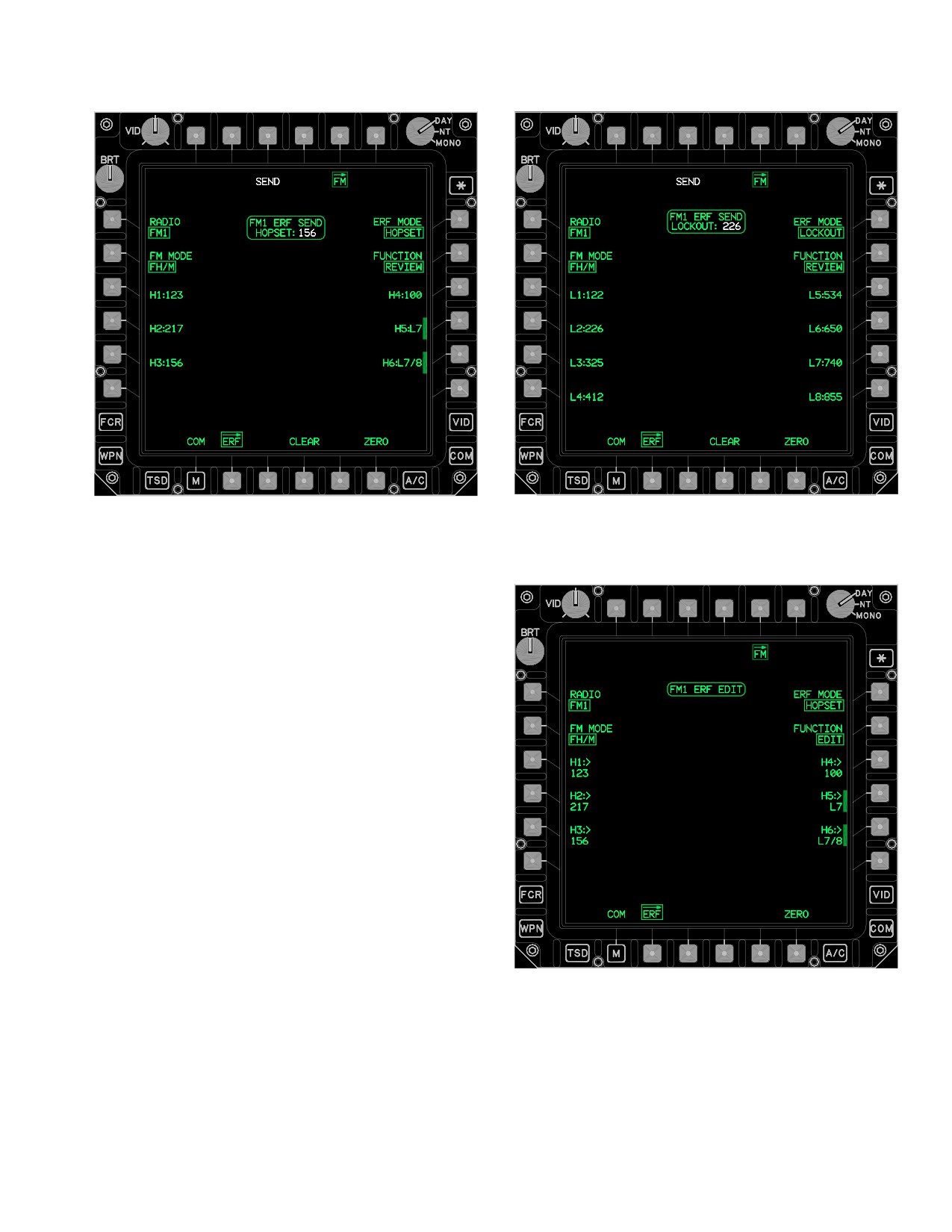
TM 1-1520-251-10
LBA5141
LBA5142
Figure 3A-69. ERF Page - SEND HOPSET
Figure
3A-70.
ERF Page - SEND LOCKOUT
NOTE
A YES/NO confirmation will only display
when the CLEAR button is used to clear a
received HOPSET or LOCKOUT.
3A.48.11 RECEIVE HOPSET Window. The RE-
CEIVED HOPSET window (fig 3A-65) is displayed when
the system has received a valid HOPSET. The HOPSET
will be displayed in white.
3A.48.12 RECEIVE LOCKOUT Window. The RE-
CEIVE LOCKOUT window (fig 3A-66) is displayed when
the system has received a valid LOCKOUT.
3A.48.13 ERF SEND HOPSET Window. The ERF
SEND HOPSET window (fig 3A-69) displays the hopset
data that is to be transmitted through the ERF process
with the selection of the SEND button.
3A.48.14 ERF SEND LOCKOUT Window. The ERF
SEND LOCKOUT window (fig 3A-70) displays the lockout
LBA5143
data that is to be transmitted through the ERF process
with the selection of the SEND button.
Figure
3A-71.
ERF Page - HOPSET Edit
Use or disclosure of this information is subject to the restriction(s) on the title page of this document.
Change 2
3A-63
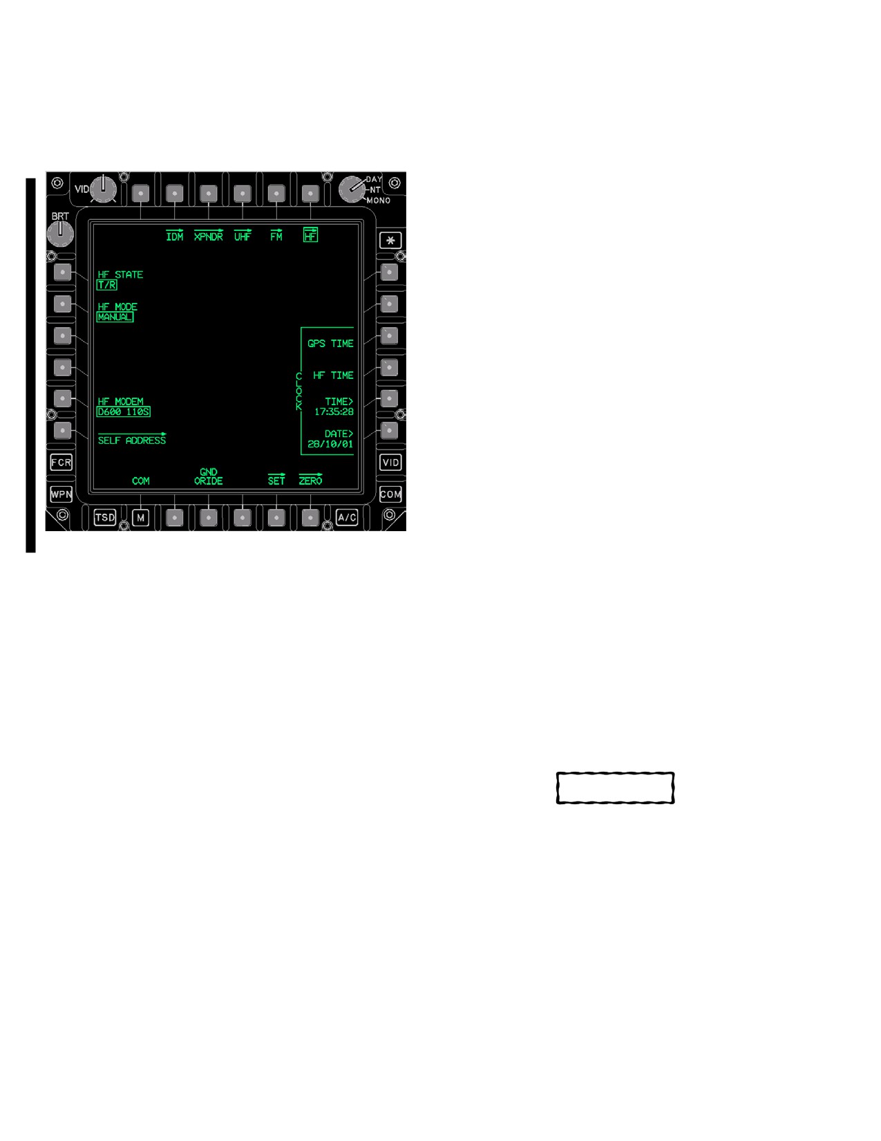
TM 1-1520-251-10
3A.49 HF PAGE
3A.49.2 HF MODE Button. The HF MODE button pro-
vides the capability to configure the HF radio into MANU-
The HF page (fig 3A-72) provides specific controls for the
AL, PRESET, ALE (Automatic Link Establishment),
ARC - 220 HF radio.
ECCM (Electronic Counter Counter Measure Frequency
Hop), or EMERGENCY. Manual mode allows for tuning of
the HF radio from the MAN page. Preset mode provides
up to 20 preprogrammed frequency channels to tune the
HF radio. ALE mode provides up to 20 preprogrammed
nets. And ECCM mode provides up to 12 preprogrammed
nets to establish links with various callers. Emergency
mode is a preprogrammed configuration of the radio for
use in an emergency.
3A.49.3 HF MODEM Button. The HF MODEM button
provides the capability to select from up to 12 prepro-
grammed modem configurations for data communica-
tions.
3A.49.4 SELF ADDRESS Page Button. The SELF
ADDRESS button displays the HF SELF ADDRESS page
(para 3A.50).
3A.49.5 CLOCK GPS TIME Button. The CLOCK GPS
TIME button causes the current time from the EGI to be
loaded into the HF radio’s internal clock. Selection of this
button changes the HF STATE to STBY.
LBA5144A
3A.49.6 CLOCK HF TIME Display Button. The
Figure 3A-72.
HF Page - MANUAL Mode
CLOCK HF TIME display button provides the capability to
get the current time and date from the HF radio and have
The HF page contains the following unique buttons when
it displayed in the CLOCK TIME and DATE buttons.
in MANUAL mode:
3A.49.7 CLOCK TIME Button. The CLOCK TIME but-
• L1
HF STATE button
ton provides the capability to view the current time in the
• L2
HF MODE button
HF radio or to change the time in the HF radio.
• L5
HF MODEM button
3A.49.8 CLOCK DATE Button. The CLOCK DATE
• L6
SELF ADDRESS page button
button provides the capability to view the current date in
• R3
CLOCK GPS TIME button
the HF radio or to change the date in the HF radio.
• R4
CLOCK HF TIME DISPLAY button
• R5
CLOCK TIME button
CAUTION
• R6
CLOCK DATE entry button
• B3
GND ORIDE button
There are no UFD/EUFD indications
• B5
SET page button
when the HF radio override is selected.
• B6
ZERO page button
3A.49.9 GND ORIDE Button. The GND ORIDE button
3A.49.1 HF STATE Button. The HF STATE button pro-
provides the capability when selected, to override the
vides the capability to set the HF radio to STBY (Standby),
safety inhibits, in order to transmit on the HF radio while
SILENT, or T/R (Transmit/Receive). Standby is the power
the aircraft is on the ground.
up mode of the HF radio. Silent mode allows reception of
voice and data, but not automated transmissions. Manual
3A.49.10 SET Button. The SET button displays the HF
transmissions of voice (using PTT switch) and data (using
SET page (para 3A.58).
HF SEND buttons) are still possible while in Silent mode.
Normal HF radio operations occur when in the Transmit/
3A.49.11 ZERO Button. The ZERO button displays the
Receive mode.
HF ZERO page (para 3A.59).
Use or disclosure of this information is subject to the restriction(s) on the title page of this document.
3A-64
Change 4
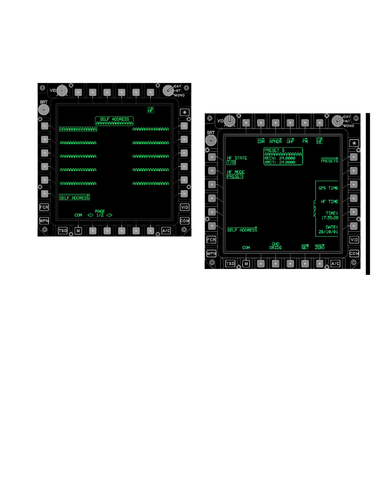
TM 1-1520-251-10
3A.50 HF SELF ADDRESS PAGE
3A.50.3 HF SELF ADDRESS Status Window. The HF
SELF ADDRESS status window displays the current self
The HF SELF ADDRESS page (fig 3A-73) provides up to
address selected in the HF radio.
20 non - modifiable self address options for selection.
3A.51 HF PAGE - PRESET MODE
The HF PRESET Mode (fig 3A-74) provides specific con-
trols and status when the HF radio is in the Preset mode.
LBA5145
Figure 3A-73. HF SELF ADDRESS Page
LBA5146A
The HF SELF ADDRESS page contains the following
unique buttons:
Figure 3A-74. HF Page - PRESET Mode
• L1 - L5
HF self address option buttons
• R1 - R5
HF self address option buttons
The HF page contains the following unique button when in
PRESET mode:
• B2
PAGE Back button
• B3
PAGE Forward button
• R1
PRESETS page button
3A.50.1 HF Self Address Option Buttons. The HF
3A.51.1 PRESETS Page Button. The PRESET button
self address option buttons provide the capability to select
displays the HF PRESETS page (para 3A.52).
from up to 20 non - modifiable self addresses in the HF ra-
dio.
3A.51.2 HF PRESET Status Window. The HF PRE-
SET status window displays the current preset channel
3A.50.2 PAGE Back and Forward Buttons. Allows
number, name, and receive/transmit frequencies when
selection between two pages of HF self addresses.
the HF radio is in Preset mode.
Use or disclosure of this information is subject to the restriction(s) on the title page of this document.
Change 4
3A-65
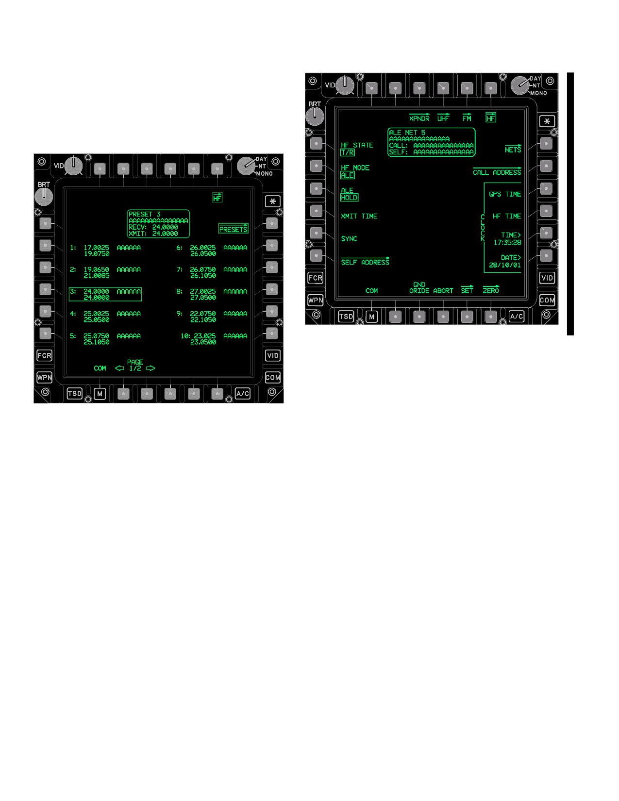
TM 1-1520-251-10
3A.52 HF PRESETS PAGE
The HF PRESETS page (fig 3A-75) provides up to 20
non - modifiable preset channels for selection, when the
HF radio is in the Preset mode.
LBA5148A
Figure 3A-76. HF Page - ALE Mode
The HF page contains the following unique buttons when
in ALE mode:
• L3
ALE HOLD/SCAN button
LBA5147
• L4
XMIT TIME button
Figure 3A-75. HF PRESETS Page
• L5
SYNC button
• R1
NETS page button
• R2
CALL ADDRESS page button
The HF PRESETS page contains the following unique
buttons:
• B4
ABORT button
3A.53.1 ALE HOLD/SCAN Button. The ALE HOLD/
• L2 - L6
HF preset channel buttons
SCAN button toggles between HOLD and SCAN.
• R2 - R6
HF preset channel buttons
3A.53.2 XMIT TIME Button. The XMIT TIME button
• B2
PAGE Back button
provides the capability to send the HF radio’s current time
• B3
PAGE Forward button
over the current ALE net.
3A.52.1 HF Preset Channel Buttons. The HF PRE-
3A.53.3 SYNC Button. The SYNC button provides the
SET CHANNEL buttons provide the capability to select
capability to synchronize with others on the current ALE
from up to 20 non - modifiable preset channels in the HF
net.
radio.
3A.53.4 NETS Page Button. The NETS page button
3A.52.2 PAGE Back and PAGE Forward Buttons. Al-
displays the HF ALE NETS page (para 3A.54).
lows selection between two pages of HF preset channels.
3A.53.5 CALL ADDRESS Page Button. The CALL
ADDRESS page button displays the HF CALL ADDRESS
3A.53 HF PAGE - ALE MODE
page (para 3A.57).
The HF ALE Mode (fig 3A-76) provides specific controls
3A.53.6 ABORT Button. The ALE ABORT button pro-
and status when the HF radio is in the ALE mode.
vides the capability to abort any ALE function in progress.
Use or disclosure of this information is subject to the restriction(s) on the title page of this document.
3A-66
Change 4
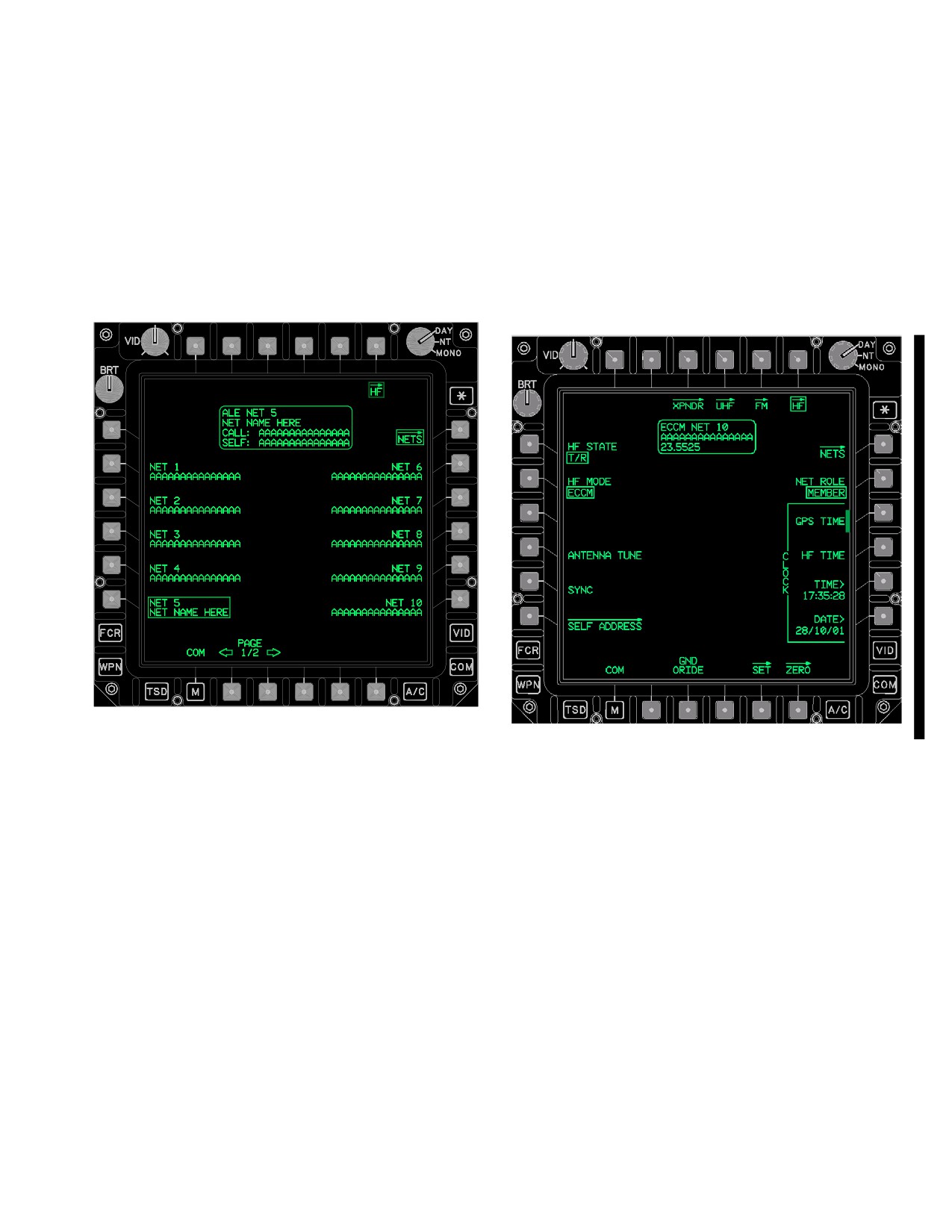
TM 1-1520-251-10
3A.53.7 ALE Status Window. The ALE status window
3A.54.2 PAGE Back and PAGE Forward Buttons. Al-
displays the current ALE net number, name, call address,
low selection between two pages of HF ALE nets.
and self address, when the HF radio is in ALE mode.
3A.55 HF PAGE - ECCM MODE
3A.54 HF ALE NETS PAGE
The HF ECCM Mode page (fig 3A-78) provides specific
controls and status when the HF radio is in the ECCM
The HF ALE NETS page (fig 3A-77) provides up to 20
mode. In ECCM operation the HF radio will frequency hop
non - modifiable ALE nets for selection.
on a set of frequencies. Each radio in the net must have
the same ECCM data fill and time of day to interchange
voice or data in this mode.
LBA5149
LBA5150A
Figure 3A-78. HF Page - ECCM Mode
Figure 3A-77. HF ALE NETS Page
The HF ECCM Mode page contains the following unique
buttons:
The HF ALE NETS page contains the following unique
buttons:
• L3
ANTENNA TUNE button
• L4
SYNC button
• R2 - R6
NET (1 - 5) option buttons
• R2
NET ROLE button
• L2 - L6
NET (6 - 10) option buttons
3A.55.1 ANTENNA TUNE Button. Selecting the AN-
• B2
PAGE Back button
TENNA TUNE button initiates tuning of the ECCM scan-
• B3
PAGE Forward button
set.
3A.54.1 NET (1 - 10) Option Buttons. Option buttons
3A.55.2 SYNC Button. Selecting the SYNC button ini-
provide the capability to select from up to 20 non - modifi-
tiates an ECCM time synchronization of the ECCM scan-
able ALE nets in the HF radio.
set.
Use or disclosure of this information is subject to the restriction(s) on the title page of this document.
Change 4
3A-67
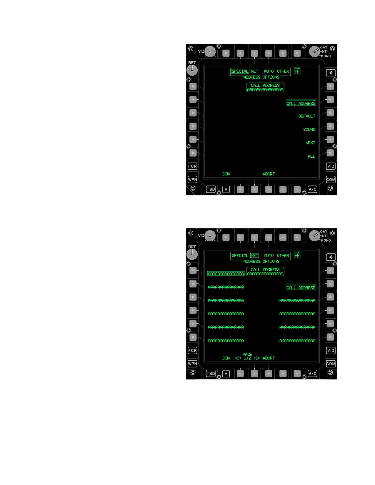
TM 1-1520-251-10
3A.55.3 NET ROLE Button. The NET ROLE button
provides the capability to select the Net Role of the own-
ship when the HF radio is in ECCM mode. The multi - state
options are:
• MEMBER, to select Member
• ALT TIME SERVER, to select Alternate Net Time
Server
• TIME SERVER, to select Net Time Server
Member is the default role upon power - up.
3A.56 HF ECCM NETS PAGE
Selecting the ECCM NETS page button calls the ECCM
NETS page to display. The HF ECCM NETS page pro-
vides up to 12 non - modifiable ECCM nets for selection
(fig 3A-77). The ECCM NETS page status window will dis-
play ECCM NET with the selected number of the selected
net.
The HF ECCM NETS page contains the following unique
buttons:
LBA5151
• R2 - R6
NET (1 - 5) options button
Figure
3A-79.
HF CALL ADDRESS Page (SPECIAL
• L2 - L6
NET (6 - 10) options button
Selected)
• B2
PAGE Back button
• B3
PAGE Forward button
3A.57 HF CALL ADDRESS PAGE
The HF CALL ADDRESS page (fig 3A-79, 3A-80, 3A-81,
and 3A-82) provides special call address controls, includ-
ing up to 20 non - modifiable Star Net call addresses, up to
20 non - modifiable Auto call addresses, and up to 100
Other call addresses for selection.
LBA5152
Figure 3A-80. HF CALL ADDRESS Page (NET
Selected)
Use or disclosure of this information is subject to the restriction(s) on the title page of this document.
3A-68
Change 2
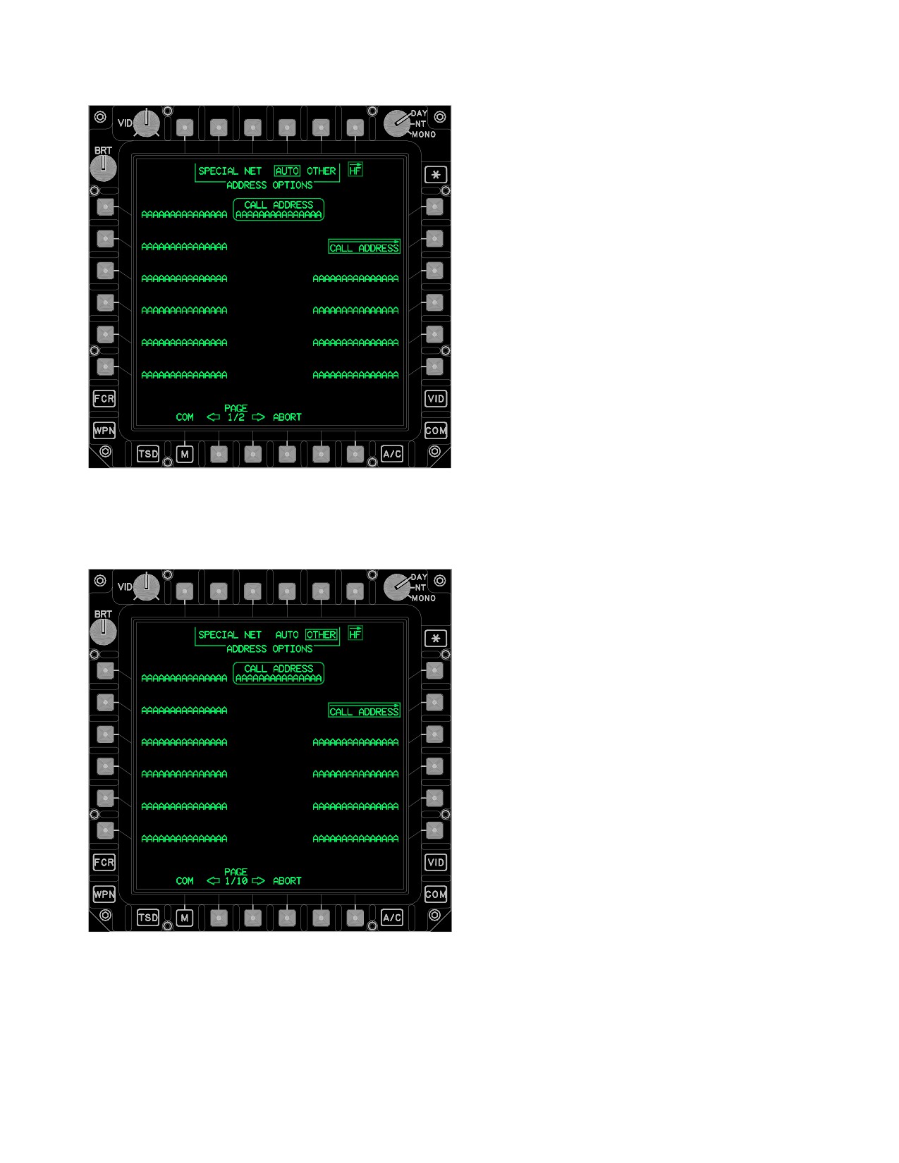
TM 1-1520-251-10
The HF CALL ADDRESS page contains the following
unique buttons when SPECIAL is selected:
• T2 - T5
ADDRESS OPTIONS buttons
• R3
DEFAULT button
• R4
SOUND button
• R5
NEXT button
• R6
ALL button
• B3
ABORT button
3A.57.1 ADDRESS OPTIONS Buttons. The AD-
DRESS OPTIONS buttons provide the capability to select
between SPECIAL, NET (Star Net), AUTO, or OTHER
call address selection options.
3A.57.2 DEFAULT Button. The DEFAULT button sets
the call address to the default call address for the current
ALE net.
3A.57.3 SOUND Button. The SOUND button sets the
LBA5153
current call address to SOUND and initiates sounding on
the current ALE net. This function can be terminated pre-
Figure
3A-81.
HF CALL ADDRESS Page (AUTO
maturely by selecting the ABORT button.
Selected)
3A.57.4 NEXT Button. The NEXT button sets the last
linked with call address for the current net and then tries to
connect on channels in the ranked channel list for the net
that would be considered poorer channels. This function
can be terminated prematurely by selecting the ABORT
button.
3A.57.5 ALL Button. The ALL button sets the call ad-
dress to ALL for the current ALE net and allows a call to all
ALE stations in the network.
3A.57.6 ALL Button. The ABORT button provides the
capability to abort any ALE function in progress.
3A.57.7 ALL Button. The HF CALL ADDRESS status
window displays the current Call Address selected in the
HF radio.
The HF CALL ADDRESS page contains the following
unique buttons when NET is selected:
• L1 - L6
NET CALL ADDRESS buttons
• R3 - R6
NET CALL ADDRESS buttons
LBA5154
• B2
PAGE Back button
Figure
3A-82.
HF CALL ADDRESS Page (OTHER
Selected)
• B3
PAGE Forward button
Use or disclosure of this information is subject to the restriction(s) on the title page of this document.
Change 2
3A-69
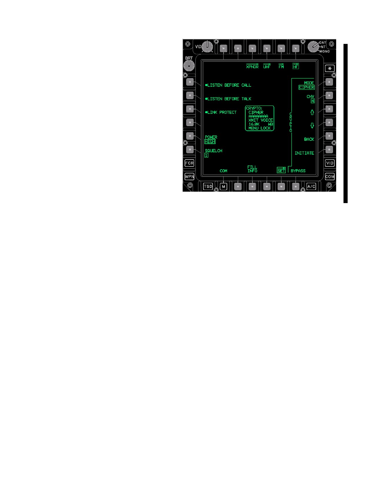
TM 1-1520-251-10
3A.57.8 NET CALL ADDRESS Buttons. The NET
CALL ADDRESS buttons provide the capability to select
from up to 20 non - modifiable Star Net Call Addresses in
the HF radio.
3A.57.9 PAGE Back and PAGE Forward But-
tons. These buttons allow selection between two pages
of HF Star Net Call Addresses.
The HF CALL ADDRESS page contains the following
unique buttons when AUTO is selected:
• L1 - L6
AUTO CALL ADDRESS buttons
• R3 - R6
AUTO CALL ADDRESS buttons
LBA5155A
Figure 3A-83. HF SET Page
3A.57.10 AUTO CALL ADDRESS Buttons. The
AUTO CALL ADDRESS buttons provide the capability to
The HF SET page contains the following unique buttons:
select from up to 20 non - modifiable Auto Call Addresses
• L1
LISTEN BEFORE CALL button
in the HF radio.
• L2
LISTEN BEFORE TALK button
• L3
LINK PROTECT button
• L5
POWER button
The HF CALL ADDRESS page contains the following
• L6
SQUELCH button
unique buttons when OTHER is selected:
•
R1
CRYPTO MODE button
• R2
CRYPTO CNV button
• L1 - L6
OTHER CALL ADDRESS buttons
• R3
CRYPTO UP ARROW button
• R4
CRYPTO DOWN ARROW button
• R3 - R6
OTHER CALL ADDRESS buttons
•
R5
BACK button
• R6
CRYPTO INITIATE button
3A.57.11 OTHER CALL ADDRESS Buttons. The
• B3
FILL INFO button
OTHER CALL ADDRESS buttons provide the capability to
• B6
CRYPTO BYPASS button
select from up to 100 non - modifiable Other Call Address-
3A.58.1 LISTEN BEFORE CALL Button. The LISTEN
es in the HF radio.
BEFORE CALL button enables/disables the listen before
call function in the HF radio.
3A.58.2 LISTEN BEFORE TALK Button. The LISTEN
3A.58 HF SET PAGE
BEFORE TALK button enables/disables the listen before
talk function in the HF radio.
3A.58.3 LINK PROTECT Button. The LINK PRO-
The HF SET page (fig 3A-83) provides on/off and ancillary
TECT button enables/disables ALE link protection in the
controls.
HF radio.
Use or disclosure of this information is subject to the restriction(s) on the title page of this document.
3A-70
Change 4
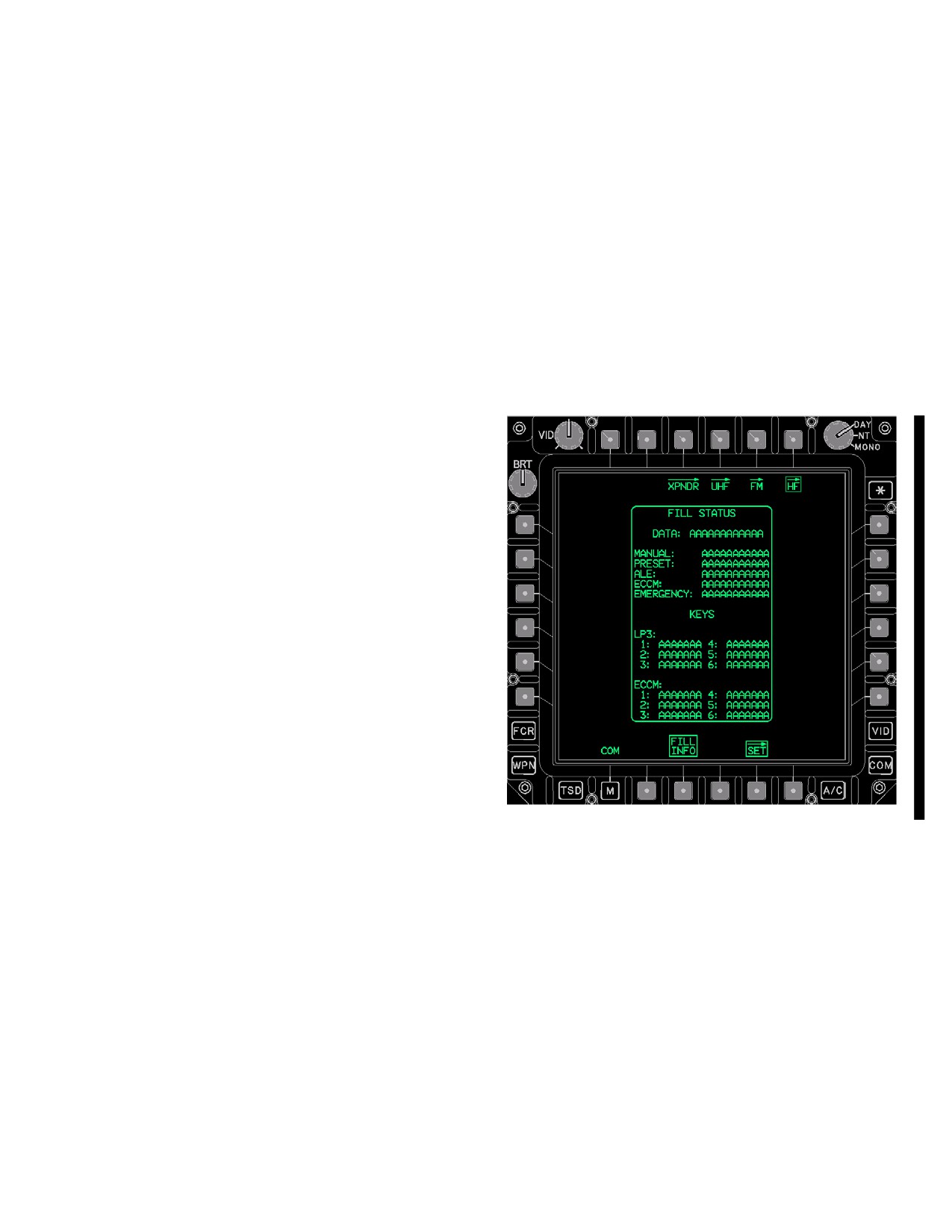
TM 1-1520-251-10
3A.58.4 HF POWER Button. The HF POWER button
3A.58.11 BACK Button. The HF BACK button pro-
provides the capability to set the HF radio power output to
vides the capability to back out of KY - 100 menus.
LOW, MEDIUM, or HIGH.
3A.58.12 HF FILL INFO Button. Selection of the HF
3A.58.5 HF SQUELCH Button. The HF SQUELCH
FILL INFO button commands the HF FILL status window
button provides the capability to set the HF radio squelch
to display.
level to 1, 2, 3, 4, or 5, which takes affect when squelch is
enabled from the COMM Panel.
3A.58.13 HF CRYPTO BYPASS Button. The HF
CRYPTO BYPASS button provides the capability to by-
3A.58.6 HF CRYPTO MODE Button. The HF CRYPTO
pass the HF radio’s crypto device in case of failure.
button provides the capability to control the operation of
the HF radio’s Crypto device. The button provides the op-
3A.58.14 FILL STATUS Window. The FILL STATUS
tions of:
window (fig 3A-84) displays the fill status of data in the HF
radio. The FILL STATUS window is not available while a
1) PLAIN, for non - encrypted communication;
fill is in progress.
2) CIPHER (for encrypted communication);
3) RECEIVE, to receive a Crypto Net Variable through the
RF link process;
4) OFFLINE, to turn off Crypto device.
The Crypto data field on the EUFD is updated when the
mode is changed. The Crypto state is uploadable from the
Data Transfer Cartridge. Upon power up, the last Crypto
state used is restored.
3A.58.7 HF CRYPTO CNV Button. The HF CNV but-
ton provides the capability to change the HF Crypto Net
Variable. The button provides 6 (1 through 6) variable op-
tions. The HF CNV data field on the EUFD is updated
when the code has been modified. The HF Crypto Net
Variable option may be set via the AMPS. Upon power up,
the last HF Crypto Net Variable option is used.
3A.58.8 HF CRYPTO UP ARROW Button. The HF
CRYPTO UP ARROW button provides the capability to
LBA5156A
scroll up thru the KY - 100’s menu system.
Figure 3A-84.
HF SET Page (FILL INFO Selected)
3A.58.9 HF CRYPTO DOWN ARROW Button. The HF
CRYPTO DOWN ARROW button provides the capability
to scroll up thru the KY - 100’s menu system.
3A.59 HF ZERO PAGE
3A.58.10 HF CRYPTO INITIATE Button. The HF
The HF ZERO page (fig 3A-85) provides controls to zer-
CRYPTO INITIATE button provides the capability to initi-
oize either data or keys in the HF radio, for diagnostic pur-
ate selections from the KY - 100 menus.
poses.
Use or disclosure of this information is subject to the restriction(s) on the title page of this document.
Change 4
3A-71
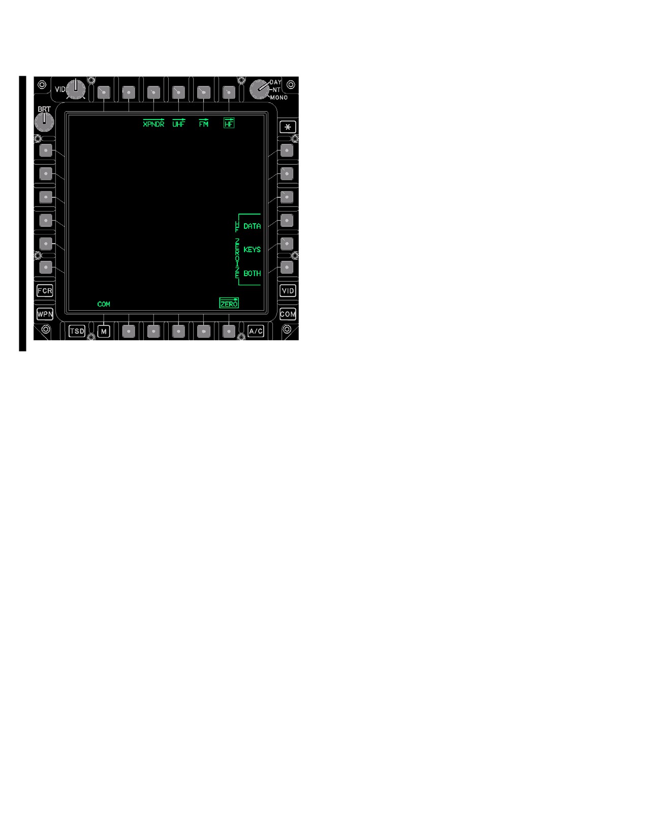
TM 1-1520-251-10
The HF ZERO page contains the following unique but-
tons:
• R4
HF ZEROIZE DATA button
• R5
HF ZEROIZE KEYS button
• R6
HF ZEROIZE BOTH button
3A.59.1 HF ZEROIZE DATA Button. The HF ZER-
OIZE DATA button will zeroize non - key data in the HF ra-
dio. Selection of this button will prompt for a YES or NO
confirmation to initiate the zeroize.
3A.59.2 HF ZEROIZE KEYS Button. The HF ZER-
OIZE KEYS button will zeroize LP1 and LP2 keys in the
HF radio. Selection of this button will prompt for a YES or
NO confirmation to initiate the zeroize.
3A.59.3 HF ZEROIZE BOTH Button. The HF ZER-
OIZE BOTH button will zeroize all data and keys in the HF
radio. Selection of this button will prompt for a YES or NO
LBA5157A
confirmation to initiate the zeroize.
Figure 3A-85. HF ZERO Page
Use or disclosure of this information is subject to the restriction(s) on the title page of this document.
3A-72
Change 4
TM 1-1520-251-10
3A.60 ARC-164 HAVE QUICK (HQ) PROCEDURES
When using the TSET segment list for
training, NET numbers are 0z.z25. The
3A.60.1
Automatic Loading HQ Data.
suffix of 25 specifies that the TSET fre-
quency list in the radio is to be used for
NOTE
hopping. The z.z is any number 0.0 to 1.5
and designates which of the frequencies
• When using the DTU to load HQ WOD
in the list will be used to start hopping.
data into the aircraft, all HQ WOD data is
loaded.
1.
COM - Select.
• HQ FMT data must be entered manually
into the aircraft. There is no DTU upload
2.
UHF - Select.
capability. HQ FMT data is the same data
for the UHF radio.
3.
WOD - Select.
1.
DTU - Select MASTER LOAD.
4.
WOD Day number - Enter.
or
5.
Enter WOD Segments1 through 6.
2.
DTU DATA COMMUNICATIONS - Select ALL
or MWOD.
6.
UPDATE - Press.
3A.60.2
Manual Loading HQ Data.
7.
Repeat steps 4 through 6 as necessary until all
NOTE
WOD Segments have been entered.
• The last two digits of the first segment in
8.
WOD - Deselect.
any WOD specifies the hoprate in the FH
mode:
xxx.x00 (slowest)
9.
NET - Enter.
xxx.x25
xxx.x50
10.
CAL DAY - Enter.
xxx.x75 (fastest)
Best results for FH (secure), use hop-
11.
UHF - Deselect when complete.
rates between xxx.x00 or xxx.x25.
• The calendar day (via GPS/RECEIVE
or
TOD/CAL DAY) number specifies which
WOD segment list the radio will use.
If FMT values are to be entered, perform the
following:
• Operational NET numbers are allocated
as follows:
12. UHF - Select.
yy.y00 - HQ1 Mode
yy.y25 - HQ2 NATO usage
yy.y50 - HQ2 non-NATO countries
13. FMT - Select.
Where y is any number 0 to 9. All other
operational NET number combinations
14. Enter FMT Frequencies1 through 16.
are illegal.
• Training NET numbers are allocated as
15. UPDATE - Press.
follows:
When using WOD segment lists for train-
16. FMT - Deselect.
ing (first segment in a given WOD must
be 300.0xx), NET numbers are 00.z00.
17. NET - Enter.
Where z is any number 0 to 4; z specifies
which of the frequencies in the WOD seg-
ments hopping will start on.
18. UHF - Deselect.
Use or disclosure of this information is subject to the restriction(s) on the title page of this document.
Change 3
3A-73
TM 1-1520-251-10
3A.60.3
Update FMT.
3A.60.8 Activation of HAVEQUICK (Frequency Hop-
ping).
1.
UHF - Select.
1. Automatic load HQ data (para 3A.60.1).
2.
FMT - Select.
or
2. Manual load HQ data (para 3A.60.2).
3.
TRAINING UPDATE - Press.
3. Update WOD or FMT segments in radio (para
4.
FMT - Deselect.
3A.62.3).
4. UHF - Select.
5.
UHF - Deselect.
5. UHF MODE - Select FH (verify no tone).
3A.60.4
Receive TOD Signal.
6. UHF - Deselect.
1.
UHF - Select (verify correct frequency).
3A.61 EMERGENCY LOCATOR TRANSMITTER
CHECK PROCEDURE
2.
RECEIVE - Select, can now receive TOD for the
NOTE
next 60 seconds.
If the UHF GUARD RECEIVER is enabled
during aircraft power up and the ELT warble
3.
UHF - Deselect.
tone is not heard, the following check is not
required.
3A.60.5
Create Cold Start TOD.
1. EMERGENCY PANEL GUARD button - Press
or manually input 121.500/243.000.
1.
UHF - Select.
2. Guard frequency - Monitor for ELT warble tone.
2.
CAL DAY - Enter.
if warble tone is heard:
3.
COLD START - Press.
3. ELT OFF - TEST/ARM/ON switch - Reset OFF -
TEST switch.
4.
UHF - Deselect.
3A.62 ARC-201D FM PROCEDURES
3A.60.6
Create GPS TOD.
NOTE
• Selections on the FM page take 3 to 4
1.
UHF - Select.
seconds to complete in changing the
modes of the ARC-201D radio. DO NOT
2.
GPS TIME - Press.
make a second or subsequent selection
until the first selection OPERATION IN
PROGRESS is complete.
3.
UHF - Deselect.
• In order to send or receive an ERF, using
the MAN hopset, a hopset must be stored
3A.60.7
Send TOD.
in location 1 in the ARC-201D radio.
• An ERF procedure (ERF SEND or ERF
1.
UHF - Select (verify correct frequency).
RECEIVE) WILL NOT work correctly if
the MAN and CUE frequencies are the
2.
SEND - Press.
same while in FH/M mode with the MAN
hopset selected. Avoid setting the same
3.
UHF - Deselect.
frequency for MAN and CUE.
Use or disclosure of this information is subject to the restriction(s) on the title page of this document.
3A-74
Change 2
TM 1-1520-251-10
3A.62.1 Automatic Loading of SINCGARS Data.
3A.62.3 Set Base Time-of-Day (TOD)/NET (Hopset)
Synchronization.
NOTE
NOTE
• To ensure all aircraft will use approxi-
The DTU will automatically load the initial
mately the same TOD within ± 4 seconds,
power-up, MAN, and CUE frequencies for
select the CLOCK GPS TIME button.
each radio. It WILL NOT load the hopset
Other methods are permissible but may
require more detailed coordination; any
and lockout set data. This must be done
method used must ensure that the base
through the LMP.
TOD is within ± 4 seconds.
• The base TOD only needs to be set once,
but the ERF SEND/RECEIVE procedure
1.
DTU - Select MASTER LOAD.
for final synchronization must be accom-
plished with each Net Control Station
(Hopset) using different base times.
2.
DTU DATA COMMUNICATIONS - Select ALL.
•
After TOD synchronization, if the
ARC-201D radio battery backup is
installed with good batteries, the radio will
3A.62.2
Manual Loading of SINCGARS Data.
hold synchronization for approximately
24 hours after aircraft power is off.
1.
FM - Select.
1.
COM - Select.
2.
RADIO - Select FM1 or FM2 as desired.
2.
FM - Select.
3.
GPS TIME - Press.
4.
FM DATE/TIME - Verify correct time is dis-
3.
RADIO - Select FM1 or FM2 as desired.
played.
If GPS time is unsuccessful or manual time
entry is desired, proceed to step 5
4.
MAN frequency - Enter.
5. FM DATE/TIME - Enter date, hours, and min-
utes in 24 hour format.
5.
CUE frequency - Enter.
If NET (Hopset) Synchronization only is re-
quired, perform the following Cold Start pro-
cedure:
6.
HOPSET - Select to verify loaded hopsets.
6. RADIO - Select FM1 or FM2, if required.
7. Execute ERF SEND/ERF RECEIVE procedure,
7.
HOPSET - Select.
as appropriate, to complete synchronization.
8. Repeat step 7, as necessary, for each different
Net Control Station (Hopset) that will be used.
8.
Repeat steps 3 through 7 for other FM radio, as
desired.
9. Repeat steps 2 through 8 for other FM radio, as
desired.
9.
FM - Deselect.
10. FM - Deselect.
Use or disclosure of this information is subject to the restriction(s) on the title page of this document.
Change 2
3A-75
TM 1-1520-251-10
3A.62.4
ERF Send.
11. Repeat steps 8 or 9 as necessary to complete
ERF transfer for all hopsets and lockout sets de-
1.
FM - Select.
sired.
2.
Automatic Loading of SINCGARS data
12. ERF - Deselect.
(para 3A.62.1).
or
13. FM - Deselect.
3.
Manual Loading of SINCGARS Data
3A.62.6 Activate Frequency Hopping Mode.
(para 3A.62.2).
4.
RADIO - Select FM1 or FM2 as desired.
1. FM - Select.
5.
HOPSET - Select MAN.
2. RADIO - Select FM1 or FM2 as desired.
6.
FM MODE - Select FH/M.
3. NET (Hopset) Synchronization (para 3A.62.6) -
7.
ERF - Select.
Verify complete.
8.
FUNCTION - Review.
4. HOPSET - Select desired hopset.
9.
ERF MODE - Select HOPSET or LOCKOUT as
desired.
5. FM MODE - Select FH or FH/M.
10.
HOPSET or LOCKOUT - SET - Select.
6. FM - Deselect.
11.
SEND - Select.
12.
Repeat steps 8 through 10 as necessary to com-
3A.63 COMSEC OPERATION
plete ERF transfer for all hopsets and lockout
sets desired.
3A.63.1
PRESET EDIT Method.
13.
ERF - Deselect.
14.
FM MODE - Set as desired.
1.
PRESET EDIT - Select.
3A.62.5
ERF Receive.
2.
EDIT buttons - Select V/UHF, FM, or HF as de-
sired.
1.
FM - Select.
2.
RADIO - Select FM1 or FM2 as desired.
3.
V/UHF - Select.
3.
HOPSET - Select MAN.
a. UHF MODE - Select PLAIN or CIPHER.
4.
ERF - Select.
b. UHF CNV - Select desired CNV fill number.
5.
FUNCTION - Set to Review.
4.
FM - Select.
6.
ERF MODE - Select hopset or lockout, as direc-
ted.
a. FM1 or FM2 MODE - Select PLAIN or CI-
PHER.
7.
RECEIVE - Select.
b. FM1 or FM2 CNV - Select desired CNV fill
8.
HOPSET data received - Store in desired stor-
number.
age location.
5.
HF - Select.
or
9.
LOCKOUT data received - STORE Select.
a. HF MODE - Select PLAIN or CIPHER.
10.
RECEIVE - Deselect.
b. HF CNV - Select desired CNV fill number.
Use or disclosure of this information is subject to the restriction(s) on the title page of this document.
3A-76
Change 2
TM 1-1520-251-10
3A.63.2
SET CRYPTO Operations.
4.
PRESET EDIT - Select.
1.
COM PAGE or MENU PAGE - Select.
5.
EDIT UNIT - Select (Selected on display of
page).
2.
UHF - Select.
a. UNIT ID - Select and edit as desired.
a. SET - Select.
b. CALL SIGN - Select and edit as desired.
b. CRYPTO MODE - Select PLAIN or CI-
6.
EDIT V/UHF - Select.
PHER.
a. VHF FREQ - Select and enter frequency.
c. CRYPTO CNV - Select desired CNV fill
number.
b. UHF MODE - Select CIPHER or PLAIN.
3.
FM - Select.
c. UHF CNV - Select CNV 1 - 6 as desired.
d. UHF HQ NET - Select and enter net ID.
a. SET - Select.
e. UHF FREQ - Select and enter frequency.
b. RADIO FM1 or FM2 - Select.
7.
EDIT FM - Select.
c. CRYPTO MODE - Select PLAIN or CI-
PHER.
a. FM1 MODE - Select CIPHER or PLAIN.
d. CRYPTO CNV - Select desired CNV fill
b. FM1 CNV - Select CNV 1 - 6 as desired.
number.
c. FM1 HOPSET - Select as desired.
4.
HF - Select.
d. FM1 FREQ - Select and enter frequency.
a. SET - Select.
e. FM2 MODE - Select CIPHER or PLAIN.
b. CRYPTO BYPASS - Deselect.
f. FM2 CNV - Select CNV 1 - 6 as desired.
c. CRYPTO MODE - Select PLAIN or CI-
g. FM2 HOPSET - Select as desired.
PHER.
h. FM2 FREQ - Select and enter frequency.
d. CRYPTO CNV - Select desired CNV fill
number.
8.
EDIT HF - Select.
3A.63.3
IMPROVED DATA MODEM PRESET- NET
a. HF MODE - Select CIPHER or PLAIN.
SETUP.
b. HF CNV - Select CNV 1 - 6 as desired.
3A.63.4
Automatic Loading of IDM NET Data.
c. PRESET CHAN - Select and enter 1 - 20 for
the desired preset channel.
1.
DTU - Select MASTER LOAD.
d. ALE NET - Select and enter 1 - 20 for the
desired ECCM net.
or
e. ECCM NET - Select and enter 1 - 12 for the
desired ECCM net.
2.
DTU DATA COMMUNICATIONS - Select ALL
or IDM.
f. HF RECV FREQ - Select and enter fre-
quency.
3A.63.5
Manual Loading of IDM PRESET - NET Data.
g. HF RECV EMISSION - LSB or USB as re-
quired.
1.
COM - Select.
h. HF XMIT FREQ - Select and enter frequen-
cy.
2.
DAY - Select desired day.
i. HF XMIT EMISSION - LSB or USB as re-
3.
PRESET - Select.
quired.
Use or disclosure of this information is subject to the restriction(s) on the title page of this document.
Change 2
3A-77
TM 1-1520-251-10
9. MODEM - Select.
e. NONE - Select for voice net as required.
NOTE
11.
PRESET EDIT - Deselect.
Lower baud rates for the Longbow protocol
may improve long range digital communica-
12.
NET - Select.
tions.
10. MODEM PROTOCOL - Select as required.
NOTE
a. LONGBOW - Select and set parameters as
• A maximum of 16 subscribers/team
required.
members of which 8 can be primary
(1) AUTO ACK - Select.
members
(including ownship) are
allowed when the protocol of the selected
(2) RETRIES - Select.
preset is Longbow or Internet.
• A maximum of 16 team members of
(3) BAUD RATE - Select.
which
2 can be primary members
b. TACFIRE - Select and set parameters as
(including ownship) are allowed when the
required.
protocol of the selected preset is Fire
Support.
(1) RETRIES - Select.
• Valid Longbow and Tacfire member sub-
scriber numbers range from 0 - 39, A - Z,
(2) BAUD RATE - Select.
1A - 1Z, 2A - 2Z, and 3A - 3I.
(3) AUTH - Select.
13.
NET Member location (1 - 15) - Select the de-
(4) BLOCK - Select.
sired location.
NOTE
a. MEMBER EDIT DEL - Select to clear mem-
ber data as desired.
If operating with crypto equipment, the mini-
mum preamble time that is functional is 0.7
b. MEMBER EDIT C/S - Select and enter call-
seconds.
sign as desired.
(5) PREAMBLE - Select.
c. MEMBER EDIT SUB - Select and enter
subscriber ID for Longbow or Tacfire as re-
(6) MONITOR - Select.
quired.
(7) XMIT RADIO - Select.
d. MEMBER EDIT URN - Select and enter
URN ID for Internet as required.
c. INTERNET - Select as required.
e. MEMBER EDIT URN - Select URN mode
d. FIRE SUPPORT - Select and set parame-
and edit Fire Support URN ID and IP as re-
ters as required.
quired for Fire Support.
(1) BAUD RATE - Select.
f. MEMBER EDIT TEAM - Select or deselect
as desired.
(2) NET ACCESS - Select.
g. MEMBER EDIT PRI - Select or deselect as
(3) TRAFFIC LOAD - Select.
desired.
(4) EDC FEC - Select.
14.
NET Member location (1 - 15) - Repeat step 13 a
through g as desired for other members.
(5) EDC TDC - Select.
(6) ECS SCRAMBLE - Select.
15.
NET - Deselect when completed.
Use or disclosure of this information is subject to the restriction(s) on the title page of this document.
3A-78
Change 2
TM 1-1520-251-10
3A.64 TRANSMITTING AIR FORCE APPLICATION
3A.66 TRANSMITTING JOINT VARIABLE MESSAGE
PROGRAM DEVELOPMENT (AFAPD) PROTOCOL
FORMAT (JVMF) PROTOCOL MESSAGES OVER THE
MESSAGES
FIRE SUPPORT NET
NOTE
NOTE
• The Longbow Protocol is sometimes re-
ferred to as the AFAPD protocol.
• The Fire Support Protocol is sometimes
• IDM Transmit Select must be used to se-
referred to as the JVMF protocol.
lect a radio with a valid IDM Net before
• If the message is being sent from the
transmission. The SEND selection will
ARTY page, the SEND selection will be
not be displayed if the selected radio
displayed when an FM radio is tuned to
does not have a valid IDM Net.
the Fire Support Protocol
(these
• IDM messages capable of being trans-
messages only apply to the Fire Support
mitted from the TSD or FCR displays will
Net and only one radio can be tuned to
only have the SEND selection displayed
that protocol at a time). For all other
if the member(s) have been selected.
messages, IDM Transmit Select must be
Member(s) will only be displayed on TSD
used to select a radio with a valid protocol
RPT display if they have been designated
and IDM Net before transmission. The
as primary members.
SEND selection will not be displayed if
the selected radio does not have a valid
3A.65 TRANSMITTING JOINT VARIABLE MESSAGE
protocol or IDM Net.
FORMAT (JVMF) PROTOCOL MESSAGES OVER THE
TACTICAL INTERNET
• IDM messages capable of being
transmitted from the TSD displays will
NOTE
only have the SEND selection displayed
• The Internet Protocol is sometimes
if the member(s) have been selected.
referred to as the JVMF protocol.
Member(s) will only be displayed on the
• IDM Transmit Select must be used to
TSD RPT display if they have been
select a radio with a valid protocol and
designated as primary members.
IDM Net before transmission. The SEND
selection will not be displayed if the
selected radio does not have a valid
protocol or IDM Net.
• IDM messages capable of being
transmitted from the TSD displays will
only have the SEND selection displayed
if the member(s) have been selected.
Member(s) will only be displayed on the
TSD RPT display if they have been
designated as primary members.
Use or disclosure of this information is subject to the restriction(s) on the title page of this document.
Change 2
3A-79
TM 1-1520-251-10
Table 3A-4. Messages
RADIO
Message Format
AFAPD
ATHS
JVMF
JVMF
N/A
Protocols
LONGBOW
TACFIRE
TI
FS
HF
VHF/ARC - 186
X
X
UHF/ARC - 164
X
X
FM/ARC - 201D
X
X
X
X
AN/ARC - 220HF
X
MESSAGE
TSD REC
TX
REC
TX
REC
TX
REC
TX
REC
TX
REC
FREE TEXT
X
X
X
X
X
X
X
X
MISSION 1 or 2
X
X
ALL IDM CEOI
X
X
WAYPOINT files
X
X
AREAS files
X
X
LINES files
X
X
INDIVIDUAL ROUTE file
X
X
ALL ROUTES file
X
X
TGT/THREATS files
X
X
CONTROL MEASURES files
X
X
LASER CODES (PRF only)
X
X
WAYPOINT/HAZARD
X
X
X
CONTROL MEASURE
X
X
X
TGT/THREAT
X
X
X
BDA (SHOT - AT)
X
X
X
BDA QUERY
X
X
X
FCR TARGET(S)
X
X
X
PRESENT POSITION
X
X
X
X*1
X
X*1
X
X
X
PRESENT POSITION QUERY
X
X
X
X
X
X
X
FARM
X
X
X
FARM QUERY
X
X
X
SITREP
X
X
X
X
X
SITREP REQUEST
X
X
SPOT REPORT *NOTE 4
X
X
X
X
X
PRIORITY FIRE ZONE(S)
X
X
X
NO FIRE ZONE(S)
X
X
X
FCR RFHO
X
X
X
AIR FIRE MISSION - SAL
X
X
X
REQUEST
AIR FIRE MISSION - FIRE
X
X
X
Use or disclosure of this information is subject to the restriction(s) on the title page of this document.
3A-80
Change 2