Carrier 30AWH004HB / 30AWH006HB / 30AWH008HB / 30AWH012HB. Service Manual - page 6
 

  Главная      Manuals     Carrier 30AWH004HB / 30AWH006HB / 30AWH008HB / 30AWH012HB. Service Manual (2010)


Search            copyright infringement  


Content      ..     4      5      6      7     ..


Carrier 30AWH004HB / 30AWH006HB / 30AWH008HB / 30AWH012HB. Service Manual - page 6


81

30AW

                                                     Diagnostic

6


Is the sensor correctly connected

?


(See Wiring Diagrams)


Are the resistance characteristics of the 
temperature sensor normal

?

Correctly connect the Sensor 


Replace defective Sensor 


Check Inverter board - replace if defective                                 *Check resistance table 


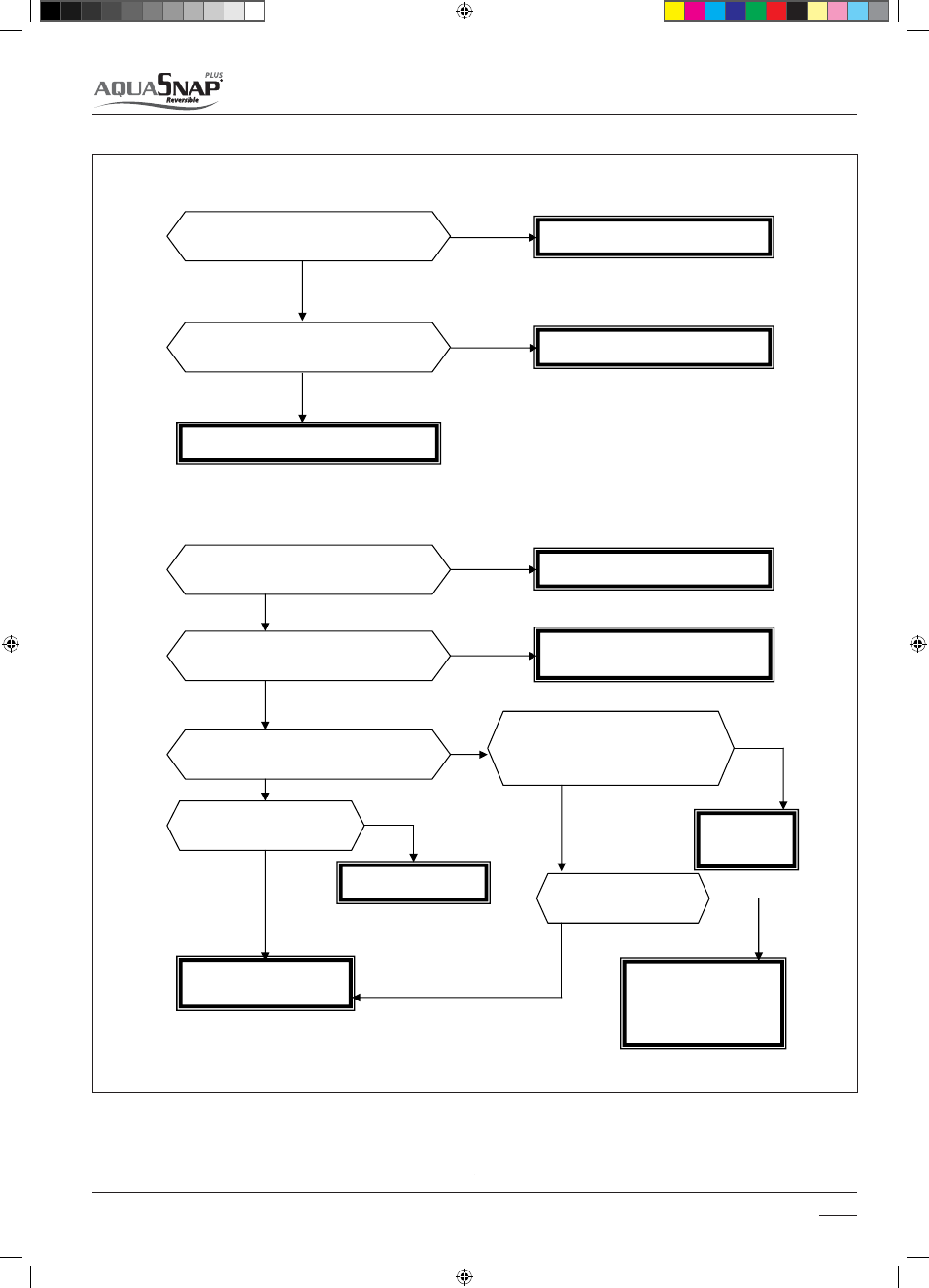
Fault code 18 – G - Tr Short-circuit protection  


Is the power supply (line) voltage correct

?


Are the inter-connections and cabling 
correct

?

 (See Wiring Diagrams) 


Does relay RY01 operate

?


Correct the power supply voltage    


Correct any inter-connecting or cabling 
errors 


Does the error code ‘Code 12 (o18

??

)’ 

appear when connector 3P is removed 
from the compressor

?


Has the AC fuse fused

?


        Replace PC 


    board 


                                                Replace PC board                               

Is compressor normal

?


Check/Replace PC board  
defective 


Replace defective 
compressor - a rare short 
circuit may have occurred 


Fault code 17 – Inverter Air sensor fault

NO 

YES 

YES 

NO 

NO 

YES 

YES 

YES 

NO 

YES 

NO 

NO 

YES 

NO 

YES 

14-03-2011   14:45:33

82

30AW

                                                     Diagnostic

6


Is the power supply cabling and sensor     
cabling correct? (See Wiring Diagrams) 


Check and correct cable 


Check inverter board 


Fault code 22 – Heat exchanger Sensors TE/TS 


Are the sensors correctly connected? 
(See Wiring Diagrams)


Are the resistance characteristics of the 
temperature sensors normal?* 

Correctly connect the Sensors 


Replace defective Sensors 


Check Inverter board - replace if defective                                  *Check resistance table 


Fault code 23 – Discharge Temperature Sensor 


Is the sensor correctly connected? 
(See Wiring Diagrams) 


Are the resistance characteristics of the 
temperature sensor normal?* 

Correctly connect the Sensor 


Replace defective Sensor 


Check Inverter board - replace if defective                                  *Check resistance table 


Fault code 21 – Inverter current sensor fault

NO 

YES 

NO 

YES 

NO 

YES 

NO 

YES 

NO 

YES 

14-03-2011   14:45:35

83

30AW

                                                     Diagnostic

6


Are connectors CN300, CN301, CN302 and CN303


connected 

correctly?*   


Is it possible to freely rotate the fan with hands  when CN300, 
CN301, CN302 & CN303 are disconnected?* 


Normal resistance value between leads: 
Between (1) (Red lead) and (2) (White lead) 
Between (2) (White lead) and (3) (Black lead) 
Between (3) (Black lead) and (1) (Red lead) on wind

ing 

connector CN301 & CN303* 


Normal resistance value between leads: 
Between _ (Yellow lead) and _ (Pink lead) of motor  connector 

CN300 & CN302 


Normal fan motor                                   

                                 Defective Fan Motor 


* 30AW004-006-008 have only CN300 connector
For the nominal resistance value, check
the 

relative 

tables. 


Note: 
A Ground circuit error inside the motor is rarely detected 
even with the above check. 
When the circuit is not normal, even after replacing the 
P.C. Board, replace the outdoor fan motor 


Fault code Fault code 24 – Outdoor fan motor error– Compressor lock

 Fan 

Motor 

Winding 

Motor position 

detection 

CN301 CN300 

30AWH012 
30AWH015 

CN303 CN302 

30AWH004 
30AWH006 
30AWH008 

CN300  

NO 

YES 

NO 

YES 

NO 

YES 

NO 


14-03-2011   14:45:36

84

30AW

                                                     Diagnostic

6


t

c

e

r

r

o

C


?

t

c

e

r

r

o

c


e

g

a

t

l

o

v


y

l

p

p

u

s


r

e

w

o

p


e

h

t


s

I

power supply voltage 


Are the connections of cables and 
connectors correct

?


Check and correct the 
cabling & connections 


Is the compressor 
functional

?


Has there been a refrigerant 
leak

?


Compressor lock - replace 


Does the electronic expansion 
valve operate normally

?


Check TE and TS Sensors, replace 
if defective  
Check expansion valve, replace if 
defective 


Check GMC & inverter Board – if 
defective, replace 


Fault code 28 – Discharge temperature error 

Fault code 27 – Compressor lock


Is the protective control, such 
as discharge temperature 
release, normal

?


 Are the connections of 
cables and connectors 
correct

?


Check and correct the 
cabling & connections 


Check parts, if defective 
replace 


Is the refrigerant charge correct

?


Does and overload condition exist

?


Are the resistance characteristics of the TD 
sensor normal

?


Check and correct the 
refrigerant charge 


Delete the cause of 
overload 
 
 
Replace the TD sensor 


Check Inverter board, 
replace if defective 


NO 

NO 

NO 

NO 

NO 

YES 

YES 

YES YES 

YES 

NO 

YES 

NO 

YES 

YES 

NO 

NO 

NO 

YES 

YES 

14-03-2011   14:45:37

85

30AW

                                                     Diagnostic

6

Fault code 29 – Compressor break down


Is the power supply voltage normal

?


Does and overload condition exist

?


Is the current detected by the current sensor 
normal

?


Correct the power supply 
voltage 


Delete the cause of 
overload 


Check and correct circuit 
cables 


Check P.C. boards, if 
defective replace. 


YES 

YES 

NO 

NO 

YES 

NO 

14-03-2011   14:45:38

86

30AW

                                                     Diagnostic

6


Fault code 14 – High temperature release 


       Does the unit operate

?


Are the inter-connecting 
cables correctly wired

?


Correct inter-connecting 
cabling 


Check  P.C. Board - if 
defect, replace 

Are the connectors 
correctly located

?


Ensure connectors are 
located correctly 


Does the voltage measured 
between _and _ on the 
terminal block (1,2,3) of 
the unit vary

?

Is a DC Voltage of 280V 
measured between the 
terminals of the electrolytic 
capacitor on inverter main 
board 


Replace inverter board 


Is a DC Voltage of 7V 
supplied to the CDB

?

  Are 

cables between Pin 2 and 
Pin 5 on CN800 normal

?


Replace inverter board / 
Ensure cabling is correct 


Is case thermocouple 
(CN500) connected

?


Connect thermocouple 
CN500 


Does case thermocouple 
operate

?


Normal Fan Motor 


Are the LEDs on receiver or 
main board flashing

?


Check receiver board, 
replace if defect 

Check & Correct refrigerant 
charge 


                                    Change GMC Board 


** S5277G or equivalent (G or J type) (Diode 
with rated voltage of 400V or more is 
acceptable).


NO 

NO 

NO 

NO 

NO 

NO 

NO 

YES 

YES 

YES 

 YES 

NO 

YES 

YES 

YES 

YES 

YES 

NO 

* As shown below, perform 
measurement within 20 seconds 
of power ON 


See DIODE data at the end of 
session

** S5277G or equivalent (G or 

J type) (Diode with rated 
voltage of 400V or more is 
acceptable).

3

2

1

+

Black

White

S5277G**

Inter - terminal block

14-03-2011   14:45:39

87

30AW

                                                     Diagnostic

6

6.4.1 Relational graph of temperature sensor resistance value and temperature

For 004, 006, 008, 012, sizes

TE,TO,TS 

s

en

s

or

0

50

100

150

200

-30

-20

-10

0

10

20

30

40

50

60

70

80

90

Temperature  [°  C]

Re

s

i

s

tence [k


]

T<10°  C

0

5

10

15

20

Re

s

i

s

tence [k ] 

T  >10°   C

Ω

Ω

TD


s

en

s

or

0

50

100

150

200

0

10

20

30

40

50

60

70

80

90

100

110 120 130 140

Temperature  [°   C]

Re

s

i

s

tence [k ]

T<50°  C

0

5

10

15

20

Re

s

i

s

tence [k ] 

T>50°   C

Ω

Ω

TR, TA 

s

en

s

or

0

5

10

15

20

0

10

20

30

40

50

60

70

Temperature  [°   C]

Re

s

i

s

tenc e  [k ]

Ω

14-03-2011   14:45:41

88

30AW

                                                     Diagnostic

6

For 004, 006, 008, 012, 015 sizes

Only 015 size

LWT,EWT 

s

en

s

or

s

0

10

20

30

40

50

60

70

80

90

100

-35

-15

5

25

45

65

85

105

125

Temperature  [°   C]

Re

s

i

s

tence [k ]

  T<50°  C

0

0.2

0.4

0.6

0.8

1

1.2

1.4

1.6

1.8

2

Re

s

i

s

tence [k ] 

T>50°C

Ω

Ω

TR, TA, TE, TS,TO 

s

en

s

or

s

0

5

10

15

20

25

30

35

40

0

20

40

60

80

100

120

Temperature  [°   C]

Re

s

i

s

tence  [k ]

Ω

TD, TL 

s

en

s

or

0

20

40

60

80

100

120

140

160

180

0

20

40

60

80

100

120

Temperature  [°  C]

Re

s

i

s

tence [k ]

Ω

14-03-2011   14:45:44

89

30AW

                                                     Diagnostic

6

6.4.1 Resistance values of main components

4

6

8

12

15

Ω

T ref

[°C]

Ω

T ref

[°C]

Ω

T ref

[°C]

Ω

T ref

[°C]

Ω

T ref

[°C]

PMV

46±4

25

46±4

25

46±4

20

46±3

20

46±3

20

4 Way

1795±150

25

1795±150

25

1765±150

24

1774±150

24

1489±150

22

Fan

motor

22±2

25

22±2

25

22.4±2

24

35.2±2

24

17.9±2

22

21.9±2

25

21.9±2

25

22.6±2

24

34.8±2

24

18.9±2

22

21.9±2

25

21.9±2

25

22.6±2

24

35±2

24

17.7±2

22

HP size: 4-6-8 kW

V1

V2

V3

Pump: NYL 63-15

Main

246.1±20

177.4±20

108.8±10

Ω

Aux

137.8±10

137.8±10

137.8±10

Ω

T ref [°C]

23

23

23

°C

HP size: 12-15 kW

V1

V2

V3

Pump: SXM 25-60

Main

144.7±15

107.3±10

70.9±7

Ω

Aux

72.8±7

72.8±7

72.8±7

Ω

T ref [°C]

23

23

23

°C

14-03-2011   14:45:44

90

30AW


   Carrier 

interfaces

7

7.1 Dry contacts control

The AquaSnap PLUS can use the following user interfaces:

ESZDPOUBDUT
UIF"RVB4OBQ1-64"83$SFNPUFDPOUSPMMFS

the 33AW-CS1 Comfort Series programmable thermostat
the Carrier Dealer Service Tool.

14-03-2011   14:45:45

91

30AW


   Carrier 

interfaces

7

7.2 33AW-RC1 user interface

WARNING:

#FGPSFJOTUBMMJOHUIFSFNPUFDPOUSPMMFSUVSOPòBMMQPXFSUPUIFVOJUUIBU

will supply power to the remote controller. Electrical shock can cause 
personal injury or death.
- Open the remote controller rear mounting base to expose mounting 

holes. The base can be removed to simplify mounting (snap apart 
carefully at hinge to separate mounting base from remainder of the 
remote controller).

- Route the remote controller wires through the large hole in the 

mounting base. Level mounting base against wall (for aesthetic value 
only).

- Mark the wall through the 2 mounting holes. Drill two 5 mm mounting 

holes in wall where marked.

- Secure mounting base correctly to wall with 2 screws and anchors 
  provided, (additional anchoring holes available for more secure 

mounting if needed) making sure all wires extend through hole in 
mounting base.

- Adjust length and routing of each wire to reach the proper terminal in 

the connector block on the mounting base. (Strip only 6 mm of 

  insulation from each wire to prevent adjacent wires from shorting 

together when connected).

- Match and connect equipment wires to proper terminals in the 
 connector block.
- Both power and communication wires must be connected correctly for 

proper remote controller operation.

- Push any excess wire into the wall and against mounting base..

14-03-2011   14:45:45

92

30AW


   Carrier 

interfaces

7

7.2.1 I/O features details

7.2.2 Main settings

On /Off

4UBOEBSE0ò.PEFPS'SFRVFODZUPDBOCFTFMFDUFECZDPEFJG

used an external thermostat

Heat / Cool

- Fixed Water Set Point can be selected for Heat (code 113) and Cool 

(code 115)

- Floating WSP based on OAT Climatic Curve can be selected (Installer 

customized CC or predefined Carrier CC) code 112, 117-125

ECO

%JòFSFOUEFMUB GSPNUP¡$POöYFE841DBOCFEFöOFEGPS)FBU

(code 114) and Cool (code 116)

Night Mode

(Frequency Reduction) To reduce max noise, max frequency can be
reduced (code 5, 6) 

Sanitary Hot Water


In case SHW dry contact input is exercised, unit is always moved in Heat 

mode at the max WSP

Water Pump

For x and NX version, 230VAC WP output is on terminal block (230V 2A 
max)

Alarm & Defrost

In case of Unit alarm or Defrost, an output is available on terminal block  
(H version 230V, X version dry contact)

External Heat Source

When an EHS is requested a 230V output is energized to drive an 
external heat source

SHW 3Way Valve

In case of SHW input is activated, unit is forced in heat mode at max 
WSP and a 230 VAC 2A max output is available to drive, a 3WV

Alarm code

An alternate 5V signal is activated to point out on SUI the error code

CODE

33AW-RC1 AND DRY-CONTACTS SETTINGS

Unit ON/OFF mode input

146

0''PS$POUSPMMFE0òDZDMF

Heating & cooling mode input

302

Heat only, Cool only or Reversible

Leaving Water Temperature 
(LWT) set-point

in heating

113

From + 20°C to +60°C

in cooling

115

From +4°C to +25°C

Climatic curve

112

No predefined Climatic Curve (Installer has to draw CC)
1-12 HTG CC
1-2 CLG CC
See Nui manual or paragraph 7.3.5 for climatic curve details.

Remote Out-door Air Temperature sensor

126

Enabled or disabled 
(when disabled the 30AWH OAT sensor is enabled)

ECO mode input

in heating

114

From 1°C to 20°C lower than LWT set-point (113)

in cooling

116

From 1°C to 10°C higher than LWT set-point (115)

Night mode

input

005

Enabled or Disabled

frequency

006

'PSNUPPGUIFDPNQSFTTPSOPNJOBMGSFRVFODZ

Sanitary Hot Water  (SHW)

demand input

-

Enabled

.BY-85BMMPXFEXJUIJOUIFDPNQSFTTPSFOWFMPQF TXJUDIPòBU¡$

3W valve output

-

Enabled

External Heat Source / Defrost output

106

Alternative heat-source (e.g. gas-boiler) or Defrost output

Alarm or Terminal Fan-coil contact

147

Alarm or terminal Fan-coil

Alarm Defrost or humidity selection

108

Alarm Defrost or humidity selection

Water pump output

-

Enabled

For more details refer to specific manuals

7.3 33AW-CS1 User interface

5ISFFEJòFSFOUBQQMJDBUJPOT

1. Service tool, for programming (customs settings) and diagnosis 

purposes, when temporarily wired to the 30AWH… 

2. All of the above, plus remote controller and programmer, when 

installed in a room that is not representative of the indoor 

  temperature and relative humidity (e.g. basement, technical room, 

garage, etc.).

3. All of the above, plus room thermostat and hygrostat, and many 

customizable functions.

14-03-2011   14:46:01

93

30AW


   Carrier 

interfaces

7

Carrier’s NUI series programmable user interface is wall-mounted, 
low-voltage user interface which maintains room temperature by 
controlling the operation of a heating and/or air conditioning system. 

i)FBUQVNQwi"JSDPOEJUJPOFSwBOEi)FBUPOMZwBSFBWBJMBCMFXJUIUIF

present versions. A variety of features are provided including separate 
heating and cooling set-points, keypad lockout, backlighting, and built-
in installer test etc. Programming features include 7-day (all days the 
same), 5/2 (Mon-Fri and Sat-Sun) and 1-day (all 7 days individually) with 
2 or 4 or 6 periods per day.
This Installation Instruction covers installation, configuration, and 
startup of NUI. For operational details, consult the Owner’s Manual.

WARNING:

#FGPSFJOTUBMMJOHUIFSFNPUFDPOUSPMMFSUVSOPòBMMQPXFSUPUIFVOJUUIBU

will supply power to the remote controller. Electrical shock can cause 
personal injury or death.

User Interface Location

· Approximately 5 ft (1.5m) from floor.
· Close to or in a frequently used room, preferably on an inside  


 partitioning wall.

· On a section of wall without pipes or duct work.
   User Interface should NOT be mounted
· Close to a window, on an outside wall, or next to a door leading to the   

 outside.

· Exposed to direct light or heat from the sun, a lamp, fireplace, or other   

 temperature-radiating objects which could cause a false reading.

· Close to or in direct airflow from supply registers and return-air  


 registers.

· In areas with poor air circulation, such as behind a door or in an alcove.

Install User Interface
 

Turn OFF all power to unit.

1. 

If an existing User Interface is being replaced:  

2. 

a. Remove existing User Interface from wall. 
b. Disconnect wires from existing User Interface, one at a time. 
c. As each wire is disconnected, record wire colour and terminal 
marking.
Open the NUI (mounting base) to expose mounting holes. The base 

3. 

can be removed to simplify mounting. Press the thumb release at 
thetop of the NUI and snap apart carefully to separate mounting 
base from remainder of the NUI.
Route the NUI wires through large hole in mounting base. Level 

4. 

mounting base against wall and mark wall through 2 mounting 
holes.
Drill two 5mm mounting holes in wall where marked.

5. 

Secure mounting base to the wall with 2 anchors and screws 

6. 

provided making sure all the wires extend through hole in the 
mounting base.
Adjust length and routing of each wire to reach proper terminal and 

7. 

connector block on mounting base with 6.5mm of extra wire. Strip 
only 6.5mm of insulation from each wire to prevent adjacent wires 
from shorting together when connected.
Match and connect equipment wires to proper terminals of the  

8. 

connector blocks. Refer to wiring diagram for more details.
Push any excess wire into wall and against mounting base. Seal hole 

9. 

JOXBMMUPQSFWFOUBJSMFBLT-FBLTDBOBòFDUPQFSBUJPO

Snap case back together. Attach thermostat to back plate by  

10. 

inserting tab on bottom edge and hinging up until top snap secures.
Close thermostat assembly making sure pins on back of circuit board 

11. 

align with sockets in connector.
Turn ON power to unit.

12. 

14-03-2011   14:46:02

94

30AW


   Carrier 

interfaces

7

7.3.1 Main functions

7.3.2 Displayed icons

User functionality (comfort):

t0OFUPVDIJOUFSGBDFUPTFMFDUEJòFSFOUSPPNUFNQFSBUVSFTFU
tQPJOUNPEF)PNF4MFFQ"XBZ
t%JTQMBZPG

t$MJNBUJDEJTQMBZ3PPN50"55BOE3PPN3)
t5JNFBOEEBZPGUIFXFFL
t)FBUTPVSDF )FBU1VNQ/JHIU4)8&)4
t.PEF0ò0òXJUIIPNFBOUJGSFF[F)FBUBOE$PPM
t"MBSNT
t3PPNTFUQPJOUNPEF

t3PPN63TFUQPJOUUPESJWFB%FIVNJEJöFS)VNJEJöFS
t4DIFEVMJOHQFSJPETEBZSPPNTQNPEF)FBU1VNQ
t0O0òBOEOJHIUPQUJPO
t3PPNTFOTPSBEKVTUNFOU
t%JòFSFOUUFNQFSBUVSFWBMVFDBOCFEJTQMBZFE
t,FZQBEDBOCFMPDLFE
t4FUQPJOUDBOCFUFNQPSBSZPSQFSNBOFOUMZNPEJöFE
t4IPSUDVUUP/JHIUNPEF CVUUPO

 for 10 sec)

t.VMUJQVSQPTFVTFS*OUFSGBDF$PNGPSU1SPHSBNNFS$POUSPMBOE4FSWJDF

tool

t.BJO$PNNJTTJPOJOHGFBUVSFT

t'PSDFPVUQVUTPOBOEUFTU)ZESBVMJDDJSDVJU DPEF
t%FöOFEJòFSFOUTZTUFNUZQFBOEVTFSJOUFSGBDF DPEF
t$POöHVSFUFSNJOBMCMPDLPVUQVUT DPEF
t8BUFSUFNQFSBUVSFTFUQPJOUTDMJNBUJDDVSWFT DPEFUP
t'SPTU1SPUFDUJPOTFUQPJOUT DPEF
t$POUSPMMFE0''TFUUJOH DPEF
t#BDLVQ)FBUFSTUSBUFHZ DPEF
t4BOJUBSZNPEFTFUVQ DPEF
t&YUFSOBM4FOTPSJOTUBMMFE DPEF

t.BJO4FSWJDFGFBUVSFT

t3FBE)FBU1VNQUFNQFSBUVSFT DPEFUP
t%JTQMBZ$PNQSFTTPS)[ DPEF
t%JTQMBZøPXTXJUDITUBUVT DPEF
t"MBSNIJTUPSZ DPEF
t%JTQMBZ$PNQSFTTPSXBUFSQVNQSVOUJNF DPEF

Room air  
temperature 

Heating mode

Cooling mode 

Home anti-freeze  
mode 

Timer on 

On / Off 

Back-up EHS 

mode 

Outdoor air 

temperature 

Alarm 

warning 

Room relative 
humidity % 

Service
mode 

Sanitary Hot 
Water Mode 

Time clock 

Day of the week 

and weekly timer 

I am at home


mode 

I am away 

mode 

I sleep


mode 

Compressor ON / Frequency reduction 

Humidifier / Dehumidifier 

Activated 

Child lock

14-03-2011   14:46:03

95

30AW


   Carrier 

interfaces

7

7.3.3 Control buttons

7.3.4 Codes table

Code Nr.

Name 

DESCRIPTION

VALUE RANGE

STANDARD

Min

Max

1

MODE

This code is use to select the Unit Mode:

2.   Cooling 
3.   Heating

-

-

2

HOME ANTIFREEZE

This code is use to enable the Home Atifreeze option when the 

TZTUFNJT0ò

1. Disable                                                                                           

1

2

1. Disable

3

HOME ANTIFREEZE 

TEMPERATURE

This code is use to select the threshold temperature value 
under witch the Home Antifreeze protection starts (-0/+2 °C of 
hysteresis).

6°C

12°C

6°C

4

ADJUST WATER 

TEMPERATURE    

SET-POINT

This code is use to adjust the water set-point changing the setted 
climatic curve. The value setted modifies the maximum tempera-
ture of heating and cooling climatic curves.

-5°C

+5°C

0°C

5

FREQUENCY 

REDUCTION MODE

This code is use to activate Silence / Frequency Reduction / Night 
mode:
1. Not Active 
2. Active

1

2

1. Not active

6

FREQUENCY 

REDUCTION VALUE

This code is use to set the value of the outdoor unit frequency 

SFEVDUJPOJO

(

ROOM MODE

This code is only displayed from the NUI based on room mode 
selection:  
1. Home  
2. Sleep 
3. Away 

1

3

1

(

CONTROL ROOM         

SET-POINT

This code displays the control room set-point set by the user.

12°C

38°C

20°C

(

ROOM AIR    

TEMPERATURE

This code displays the room air temperature read by the internal 
NUI Thermistor.

-20°C

50°C

-

10 

(

RELATIVE HUMIDITY 

SENSOR VALUE

This code displays the relative humidity value read by the internal 
NUI sensor.

0

100

-


For more details refer to specific manuals. 

Up & 

down 

Done 

Away 

Sleep 

Home 

Day/hour/min

Start time

Period 

Days 

Zone 

Mode 

Hold 

14-03-2011   14:46:18

96

30AW


   Carrier 

interfaces

7

11 

(

)

OUTDOOR 

TEMPERATURE

This code displays the Outdoor Air Temperature. The valid OAT 
value is used with this priority:
1. OAT from GMC thermistor (if it is installed)
2. OAT from inverter, read by TO sensor.

-30°C

90°C

-

12 

(

)

GMC OUTDOOR AIR 

TEMPERATURE

This code displays the Outdoor Air Temperature read by GMC 
thermistor.

-

-

-

13

TEMPERATURE ROOM 

SENSOR ADJUSTMENT

This code is use to adjust the temperature read by the sensor in 
order to recover bad positioning of the user interface.

-5°C

+5°C

0°C

14

DAY PERIOD

This code is use to select how many period per day will be availa-
ble for the scheduling:
2
4
6

2

6

4

15

HOME HEAT TEMPE-

RATURE

With this code the User can select the HOME Temperature set-
point in Heating Mode

12°C

38°C

20°C

16

HOME COOL TEMPE-

RATURE

With this code the User can select the HOME Temperature set-
point in Cooling Mode

12°C

38°C

24°C

17

SLEEP HEAT 

TEMPERATURE

With this code the User can select the SLEEP Temperature set-
point in Heating mode

12°C

38°C

18°C

18

SLEEP COOL 

TEMPERATURE

With this code the User can select the SLEEP Temperature set-
point in Cooling Mode

12°C

38°C

26°C

19

AWAY HEAT 

TEMPERATURE

With this code the User can select the AWAY Temperature set-
point in Heating mode

12°C

38°C

15°C

20

AWAY COOL 

TEMPERATURE

With this code the User can select the AWAY Temperature set-
point in Cooling Mode

12°C

38°C

28°C

21 

(

)

USER ROOM        

SET-POINT

This code displays the room set-point that the user, pressing the 
temporary/hold button, is selecting as temporary or hold.

12°C

38°C

20°C

22 

(

)

FAULT CODE

This code displays the last fault code occurred.  

-

-

-

23 

(

)

FAULT HISTORY

This code displays the recent 4 fault codes stored.

-

-

-

100

SYSTEM TYPE

This code is use to set the System type:
1.     A2W Monobloc fixed Water Temperature Value (dry contacts)
2.   A2W Monobloc Climatic Curve setup (dry contacts)
3.    A2W Monobloc Comfort with NUI
4.    A2W Monobloc Comfort with NUI as Thermostat
5.   N.A.
6.   A2W Monobloc RS485
7.   N.A.

1

7

1. A2W

101

USER INTERFACE TYPE 

This code is use to define if NUI User Interface is used and how it 
is used:
0.     Not Used (Input Relay active/SUI)
1.     NUI Installed
2.     NUI used as programmer

0

2

0. Not used

102  

(

)


NUI SOFTWARE 

RELEASE

This code displays the NUI Software Release

-

-

-

103 

(

)

NUI SOFTWARE 

VERSION

This code displays the NUI Software Version

-

-

-

104

OUTPUT TEST

This code is use to force Output ON to test (max 10 minutes):

0

9

0. No test

0. No test

1. Water pump 

2. Alarm / Ambient temperature reached 

3. External Heat Source / Defrost 

4. Alarm + Defrost / Humidity 

5. Trace Heater / Additional Water Pump 

6. 3 Way valve 

7. SUI Alarm 

8. Blank

105

RESET PUMP       

RUN-TIME

This code is use to reset the water pump timer to zero.

no

yes

no

106

EXTERNAL HEAT          

SOURCE / DEFROST

This code is use to select the output connected at PIN 4 on 
terminal strip: 
1. External Heat Source 
2. Defrost Output

1

2

1

107

HUMIDITY LIMIT

This code is use to define the humidity threshold limit to enable 
the output for the external de-humidifier system.

20

100

Code Nr.

Name 

DESCRIPTION

VALUE RANGE

STANDARD

Min

Max

14-03-2011   14:46:19


Content      ..     4      5      6      7     ..