Carrier 30AWH004HB / 30AWH006HB / 30AWH008HB / 30AWH012HB. Service Manual - page 5
 

  Главная      Manuals     Carrier 30AWH004HB / 30AWH006HB / 30AWH008HB / 30AWH012HB. Service Manual (2010)


Search            copyright infringement  


Content      ..     3      4      5      6     ..


Carrier 30AWH004HB / 30AWH006HB / 30AWH008HB / 30AWH012HB. Service Manual - page 5


65

30AW

                               Control management

5

Outdoor fan control

Allocations of fan tap revolutions

FAN  TAP

W1

W2

W3

W4

W5

W6

W7

W8

W9

WA

WB

WC

WD

WE

WF

WG

30AWH004

0

200

280

320

350

380

420

460

500

530

560

580

600

600

600

600

30AWH006

0

200

250

300

350

400

450

500

550

580

600

600

600

600

600

600

30AWH008

200

240

280

310

350

380

420

450

490

520

580

630

680

680

680

-

30AWH012

Higher fan

250

260

270

280

330

380

430

480

530

590

650

700

730

750

-

-

30AWH012

Lower fan

OFF

OFF

250

260

310

360

410

460

510

570

630

380

710

730

-

-

30AWH015

Higher fan

200

240

240

260

320

380

480

540

640

740

780

780

780

780

-

-

30AWH015

Lower fan

0

0

200

280

360

400

500

560

660

760

820

820

820

820

-

-

5XPEJòFSFOUBMHPSJUINTGPSFBDITJ[FNBOBHFGBOTQFFEPOFGPSDPPMJOHBOEPOFGPSIFBUJOHPQFSBUJPOT

1) 

Cooling fan control


004-006 sizes. 
The blowing air volume is controlled as follow:

When strong wind blows at outdoor side, the operation of heat pump continues with the fan motor stopped.

1. 

Whether the fan is locked or not detected, and the operation of heat pump stops and an alarm is displayed if the fan is 

2. 

locked.
According to each operation mode, by the conditions of outdoor temperature (TO) and compressor revolution, the 

3. 

speed of outdoor fan shown in the table is selected  

Compressor speed 

(Hz)

~ 13.8

~ 31.7

32.3 ~ MAX

MIN

MAX

MIN

MAX

MIN

MAX

TO

TO ≤ 38 °C

W3

W4

WD

WE

WF

WG

TO ≤ 28 °C

W3

W4

WB

WD

WE

WG

TO ≤ 15 °C

W3

W4

W8

WB

WA

WD

TO ≤ 5,5 °C

W2

W4

W3

W6

W5

W8

TO ≤ 0 °C

W2

W2

W2

W3

W3

W5

TO ≤ 0 °C

W1

W1

W1

W2

W2

W3

During 

ECO 

mode

TO ≤ 38 °C

W3

W4

WC

WD

WD

WE

TO ≤ 38 °C

W3

W4

W3

W4

WC

WD

When To is abnormal

WE

WG

WE

WG

WE

WG

008 size

The outdoor fan is controlled by TE, TD, and TO sensors and also revolution frequency of the operation. The outdoor is 

1. 

controlled by every 1 tap of DC fan control (15 taps).
Only during 60 seconds after the operation has started, the fan is fixed with the maximum fan tap which corresponds to 

2. 

the zone in the following table. After then the fan is controlled by TE sensor temperature.
Considering a case that TE sensor has come out of the holder, the fan is controlled so that revolution frequency of the 

3. 

fan increases regardless of TE if temperature of TD sensor has risen.

14-03-2011   14:45:13

66

30AW

The output frequency and the output voltage are controlled by AC current detected on the P.C. board.
The max current value of the inverter are shown in table below.

 015 size

The outdoor fan is controlled by TL sensor, TO sensor and the operation frequency. The outdoor fan is controlled by 

1. 

every 1 tap of DC fan control (14 taps).
Only for 60 seconds after the operation has started, the maximum fan tap corresponding to the zone in the following 

2. 

table is fixed and then the fan is controlled by temperature of TL sensor.

TO

TO < 5C

5 <= TO < 10C

10 <= TO < 15C 15 <= TO < 20C 20 <= TO < 25C

25 <= TO 

TO error

MIN

W1

W2

W3

W4

W5

WA

W1

MAX

W6

W8

WA

WC

WE

WE

WE

TE(

o

C)

46

37

34

20

+30 rpm/20 sec.

Hold zone

-30 rpm/20 sec.

MAX

MIN

Temp. range

20 Hz

or lower

20 Hz

to 45HZ

45 Hz

or higher

MIN

MAX

MIN

MAX

MIN

MAX

38 °C ≤ TO

W6

WC

W8

WC

WA

WD

29 °C ≤ TO < 38°C

W5

WB

W7

WC

W9

WC

15 °C ≤ TO < 29°C

W4

W8

W6

WA

W8

WC

5 °C ≤ TO < 15°C

W3

W6

W5

W8

W7

WA

0 °C ≤ TO < 5°C

W2

W4

W4

W6

W5

W8

- 4 °C ≤ TO < 0°C

W2

W3

W3

W5

W4

W6

TO< - 4°C

W1

W2

W1

W4

W2

W6

TO  error

W1

WC

W1

WC

W2

WD

                               Control management

5

14-03-2011   14:45:14

67

30AW

2) Heating fan control

004-006 sizes 

The blowing air volume at the outdoor unit side is controlled as follow:
1. When strong wind blows at outdoor side, the operation of heat pump continues with the fan motor stopped.
2. Whether the fan is locked or not detected, and the operation of heat pump stops and an alarm is displayed if the fan is 

locked.

3. According to each operation mode, by the conditions of outdoor temperature (TO) and compressor revolution, the 

speed of outdoor fan shown in the table is selected.

 008 size
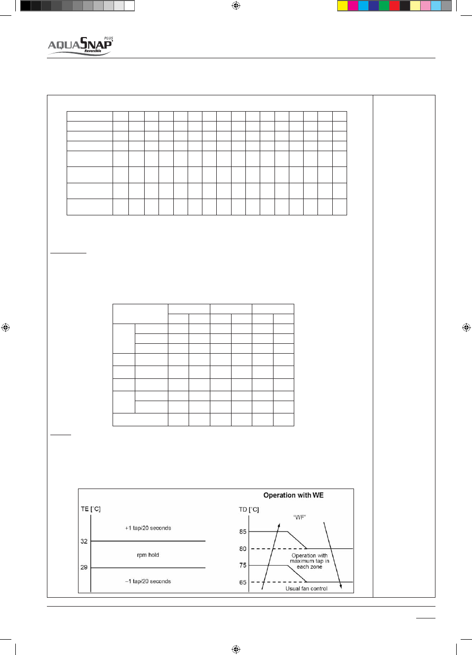
1. The outdoor fan is controlled by TE sensor, TO sensor and the operation frequency. (From Min. W1 to Max. are controlled 

according to the following table.)

2. During 3 minutes after start-up, the fan is fixed with the maximum fan tap corresponding to zone in the following table.

After then the fan is controlled by temperature of TE sensor.

3. If status, TE > 24°C continues for 5 minutes, the operation stops. This status is same to the usual Thermo-OFF which has 

no alarm display, and the fan restarts after 2 minutes and 30 seconds. This intermittent operation is not abnormal

 012 size
1. This control function lowers the fan tap according to the TE sensor value when the outdoor temperature is high.
2. When a status TE > 20C is detected continuously for 5 minutes, the operation may stop. Thisstatus does not output an error 

code and is assumed as usual status of thermo-OFF. The fan restarts after approx. 2 minutes 30 seconds and this intermittent 
operation is not an issue. 

3. This control function does not work for 30 minutes after activation, 1 minute after defrosting and during defrost operation

Control for fan tap by outdoor temperature in normal operation.

015 size
1. The outdoor fan is controlled by TE sensor, TO sensor and the operation frequency. (Control from minimum W1 to maxi-

mum (according to the following table) 

2. For 3 minutes after the operation has started, the maximum fan tap corresponding to the zone in the following table is 

fixed and then the fan is controlled by temperature of TE sensor.

3. When TE e 24°C continues for 5 minutes, the compressor stops. It is the same status as the normal thermostat- OFF 

without error display. The compressor restarts after approx. 2 minutes 30 seconds and this intermittent operation is not 
abnormal.

Compressor speed 

(Hz)

~ 16.8

~ 47.9

48.5 ~ MAX

MIN

MAX

MAX

TO

TO ≤ 15 °C

W4

W9

WA

TO < 15 °C

W4

WA

WB

TO < 5.5 °C

W9

WB

WE

TO < -5.0 °C

WC

WD

WE

During 

ECO 

mode

TO ≥ 15 °C

W4

W4

W7

TO < 15 °C

W4

W4

W9

TO < 5.5 °C

W6

W4

WA

TO < 5.5 °C

W8

WB

WC

When To is abnormal

WB

WC

WE

Temp. range

f <38.9 Hz

38.9 Hz ≤ f <67.6 Hz

67.6 Hz ≤ f

10 °C ≤ TO

W7

W8

W9

5 °C ≤ TO < 10°C

WA

WB

WD

-5 °C ≤ TO < 5°C

WE

WF

WF

TO ≤ - 5°C

WE

WF

WF

TO error

WE

WF

WF

TO

10≤TO

5≤TO<10

TO<5

MIN

W1

W1

W1

MAX

WE

WE

WE

Temp. range

20 Hz or lower

20 Hz to 45HZ

45 Hz or higher

MAX

MAX

MAX

10 °C ≤ TO

W7

W8

W9

5 °C ≤ TO < 10°C

W9

WA

WB

-3 °C ≤ TO < 5°C

WB

WB

WC

-10 °C ≤ TO < -3°C

WC

WC

WC

TO ≤ - 10°C

WD

WD

WD

TO  error

WD

WD

WD

                               Control management

5

14-03-2011   14:45:15

68

30AW

Coil heating control (compressor warm up process)

5IJTDPOUSPMSPVUJOFNBJOUBJOTTVóDJFOUMZIFBUFEUIFDPNQSFTTPSTUPQQFECZQPXFSJOHPOUIFXJOEJOHTJOTUFBEPGB

crankcase heater. The control purpose is to prevent slackness of refrigerant inside the compressor.

5PBWPJEDPNQSFTTPSEBNBHJOHEVSJOHUIFJOTUBMMBUJPOUFTUNPEFPSBGUFSMPOHDPNQSFTTPSPòUJNFJUTBEWJTFEUPTUBSU

the system when the control has interrupted the compressor warm up process.

3. A judgment for electricity is performed by TD and TO sensors. In the event of TO sensor failure, a backup control is auto-

matically performed by TE sensor (judging the TO sensor defect checking the outdoor LED display).

4. The right coil heating is controlled by TD and TE sensor.

'PSFBDINPEFMUIFDPNQSFTTPSXBSNVQQSPDFTTJTJOUFSSVQUFEUVSOJOHPòUIFQPXFSTVQQMZXIFO5%JT¡$PSNPSF


008 size 


004 006-008

012  015 

L 10W  10W 25W

40W* 

M 30W  30W  50W

40W 

It is not an abnormal phenomenon 
that electro-noise may be heard 
while heating the coil. 

 NOTIFICATION

JOUFSNJUUFOUQPXFSPONJOVUFTPONJOVUFTPò

TO:

 Outdoor

Temperature

TE:

 Entering

(in Heat
exchanger)
temperature

TD:

 Discharge

temperature

                               Control management

5

14-03-2011   14:45:17

69

30AW

High-Pressure suppression TE control

Over-current preventive control

Current release value shift control

1. This control routine suppresses that pressure which becomes abnormally too high during the cooling operation.

*UTUPQTUIFDPNQSFTTPSJG5&Ż¡$BOEDPVOUPOUIFFSSPSDPVOUFS"GUFSNJOVUFTTFDPOETPGDPNQSFTTPSPò UJNF

guard) if TE < 67°C, the compressor is enable to restart. After the compressor restart, the unit current is continuously con-

USPMMFEGPSNJOJNVNNJOVUFTöYJOHUIFMJNJUGSPNUPPGUIFDPOUSPMWBMVFEFöOFEGPSDVSSFOUSFMFBTFDPOUSPM

The error counter will be cleared if TE < 67 for 10 minutes of continuous operation.

3. When TE ≥ 67°C is detected again within 10 minutes, 1 is added to the error counter and restart is repeated.
4. If the errors counted are 10, the value is considered as a malfunctioning and the system operation is locked out .

TE: 

Entering

(in Heat
exchanger)
temperature

1. This control routine stops the compressor when over-current preventive circuit has detected an abnormal current.
2. The compressor restarts with error count 1 after 2 minutes 30 seconds (time guard).
3. If the error counted are 4, the value is considered as a malfunctioning and the system operation is locked out.

1. This control routine prevents troubles of the electron parts such as G-Tr of inverter compressor drive system and          

compressor’s troubles during cooling operation.

2. This control corrects the current release control value (l1) by TO sensor value.
3. The value corrected is based upon the following control diagram and correction value table.

T+8

TO[

o

C]

T+7

T+5

T+4
T+2

T+1

T

T-1

I1 x a%

I1 x b%

I1 x c%

I1 x d%

As I1

                               Control management

5

T

a

b

c

d

30AWH004

39°C

30AWH006

30AWH008

30AWH012

30AWH015

14-03-2011   14:45:18

70

30AW

Defrost control (Only in heating opearation)

In heating operation, defrost operation is performed when TE sensor temperature satisfies any condition in A zone to D 
zone.

* The minimum TE value between 10 and 15 minutes of compressor run time is stored inside the memory as TE0. TE0 is
calculated after each compressor restart in heating operation.
** 120 sec for sizes 004 , 006, 012
*** 2,5 for 004 and 006 sizes
****2,5 for 008 size

During the defrost:

tUIFSFWPMVUJPOTGSFRVFODZPGDPNQSFTTPSDIBOHFUPHVBSBOUFFUIFSJHIURVBOUJUZPGPJMJOTJEFUIFDPNQSFTTPS
tUIF1.7QPTJUJPOJTöYFE

The defrost operation is immediately finished if TE sensor temperature has become ε °C or more, or it also is also finished 
when defrost operation has continued for τ minutes.

TE: 

Entering

(in Heat
exchanger)
temperature

TE0:

 minimum

TE value
calculated 10-
15 min. after
each
compressor
restart in
heating
operation

For 004, 006 and 008 sizes, defrost operation is also finished if TE is kept at+5°C or higher for 80seconds.
For 012 and 015 sizes, defrost operation is also finished if -7 ≤ TE < 12 has continued for 60 seconds.

After defrost operation has finished, the compressor and the outdoor fan start heating operation after stopped for approx. 
50 seconds.

A zone

Defrost operation is performed in this zone when TE0-TE ≥ 3**** continued for T seconds**

B zone

Defrost operation is performed in this zone when TE0-TE ≥ 3**** continued for T seconds**

C zone

Defrost operation is performed when this zone continued for T seconds**

D zone

Defrost operation is performed when this zone continued for T seconds**

a

b

c

d (A)

(B)

(C)

(D)

27'70''

27'40''

34'

-

-5

-7

-

-20

Size 004-006

29

29

35

-

-4

-6

-10

-25

Size 008

34

40

55

90

-5

-10

-13

-18

Size 012

39

45

55

150

-5

-10

-2

-23

Size 015

size

004

006

008

012

015

Є [°C]

+8

+12

τ [min]

15

10

                               Control management

5

14-03-2011   14:45:19

71

30AW

                                                     Diagnostic

6

6.1 Diagnostic

6.1 Inverter alarms

6.1.1 Error codes 30AWH012 only

Troubles of the unit can be diagnosed by LED indications on the cycle 
control P.C. board of the unit. When multiple errors are detected, the
latest error is displayed.

t8IFO-&%JT0OUIFSFJTUIFNBJODBVTFPGUSPVCMFPOUIFPCKFDUJWFQBSU

of control at CDB side and the unit stops.

t8IFO-&%'MBTIJOHUIFSFJTUIFNBJODBVTFPGUSPVCMFPOUIFPCKFDUJWF

part of control at PC board side and the unit stops.

t8IFO DPNQSFTTPS DBTF UIFSNPTUBU PQFSBUFT UIF DPNNVOJDBUJPO JT

interrupted on the serial circuit. If the case thermostat operation happens 
continuously, a serial communication error occurs because of a serial 
message has been sent.

t#FGPSFBDIFDLDPOöSNFBDICJUPGUIF%*1TXJUDIJTTFUUP0''QPTJUJPO

LED indication and code checking

LED indication

Cycle control P.C. board

Cause

LED indication

D800

D801

D802

D803

D800 O: Red
D801 O: Yellow
D802 O: Yellow
D803 O: Yellow

G

: Flashing

)

: Off

D

: On

D

)

)

)

Heat exchanger sensor (TE) error

)

)

D

)

Suction sensor (TS) error 

D

D

)

)

Hot gas discharge sensor (TD) error

)

D

)

D

High-pressure protection error

)

D

)

)

Outdoor air temperature sensor error (TO)

D

D

D

)

Outdoor motorised fan error DC

D

)

)

D

Communication error between IPDU (Abnormal stop)

)

D

)

D

High-pressure release operation

)

D

D

)

Discharge temp. error: hot gas is too high

D

D

)

D

EEPROM error

)

)

D

D

Communication error between IPDU (No abnormal stop)

G

)

)

)

G-Tr short-circuit protection

)

G

)

)

Detect circuit error

G

G

)

)

Current sensor error

)

)

G

)

Comp. lock error

G

)

G

)

Comp. break down

LED
indication

ATTENTION: Problems of 30AWH004 -30AWH006 
-30AWH008 units can be diagnosed by GMC board.

IPDU are the Inverter Board.

14-03-2011   14:45:19

72

30AW

6.1.2 Error codes 30AWH015 only

The error which is generating at present and the latest error (Latest error 
information including present)
can be confirmed by lighting LED D800 toD804 on the control P.C. 
board.
a) When all DIP switch SW803 are OFF, the status of error which is gene-

rating at present is displayed.

b) <1> only of DIP switch SW803 is turned on, the error which generated 

before (Latest error information including present) is displayed.

c) If there is an error, any of LED D800 to D804 goes on. (Display 1)
d) When pushing the pushdown button switch SW800 for approx. 1 

second, the display is exchanged. (Display 2)

e) When pushing SW800 again or after 2 minutes, the status returns to 

that of Display 1.

(Legend)

  D800 (Yellow)

  D801 (Yellow)

  D802 (Yellow)

  D803 (Yellow)

  D804 (Yellow)

  D805 (Green)

 : Go off, 

 : Go on, 

 : Flash

Present error

SW803

ON

23

4

1

Latest error

SW803

ON

23

4

1

Di

s

play 1)

(Initial di

s

play)

Di

s

play 2)

(SW800 operation)

Error content

s

Normal

Discharge temp. sensor (TD) error

Heat exchanger temp. sensor (TE) error

Heat exchanger temp. sensor (TL) error

Outside temp. sensor (TO) error

Suction temp. sensor (TS) error

Heat sink temp. sensor (TH) error

Heat exchanger sensor (TE, TS) miswiring

EEPROM error

Compressor break down

Compressor lock

Current detection circuit error

Case thermostat operation

Model unset

Communication error between MCU

Other error (Compressor disorder, etc.)

Discharge temp. error

Power supply error

Heat sink overheat error

Gas leak detection

4-way valve reverse error

High pressure protective operation

Fan system error

Driving element short-circuit

Position detection circuit erro

                                                     Diagnostic

6

14-03-2011   14:45:21

73

30AW

TH

SW803

ON

23

4

1

SW803

SW803

SW803

ON

23

4

1

ON

23

4

1

ON

23

4

1

TD

SW803

ON

23

4

1

TA

SW803

ON

23

4

1

TE

SW803

ON

23

4

1

TC

SW803

ON

23

4

1

TS

SW803

ON

23

4

1

TCJ

SW803

ON

23

4

1

TO

SW803

ON

23

4

1

TL

SW803

ON

23

4

1

(Legend)

  D800 (Yellow)

  D803 (Yellow)

  D801 (Yellow)

  D804 (Yellow)

  D802 (Yellow)

  D805 (Green)

 : Go off, 

 : Go on

As TD, TL and TH are sensors for high temperature, there is error at normal temperature or below position.

For current value, the current for the outdoor unit only is displayed.

Item

s

etup

LED
di

s

play

Temperature 

s

en

s

or (°C)

Below –25

–25 to –21

–20 to –16

–15 to –11

–10 to – 5

–5 to –1

0 to 4

5 to 9

10 to 14

15 to 19

20 to 24

25 to 29

30 to 34

35 to 39

40 to 44

45 to 49

50 to 54

55 to 59

60 to 64

65 to 69

70 to 74

75 to 79

80 to 84

85 to 89

90 to 94

95 to 99

100 to 104

105 to 109

110 to 114

115 to 119

Over 120

Sensor error, unconnected

Current

(A)

 0 to 0.9

 1 to 1.9

 2 to 2.9

 3 to 3.9

 4 to 4.9

 5 to 5.9

 6 to 6.9

 7 to 7.9

 8 to 8.9

 9 to 9.9

10 to 10.9

11 to 11.9

12 to 12.9

13 to 13.9

14 to 14.9

15 to 15.9

16 to 16.9

17 to 17.9

18 to 18.9

19 to 19.9

20 to 20.9

21 to 21.9

22 to 22.9

23 to 23.9

24 to 24.9

25 to 25.9

26 to 26.9

27 to 27.9

28 to 28.9

29 to 29.9

30 to 30.9

Over 31

Compre

ss

or

operation

frequency

(rpm)

0 to 4

5 to 9

10 to 14

15 to 19

20 to 24

25 to 29

30 to 34

35 to 39

40 to 44

45 to 49

50 to 54

55 to 59

60 to 64

65 to 69

70 to 74

75 to 79

80 to 84

85 to 89

80 to 84

95 to 99

100 to 104

105 to 109

110 to 114

115 to 119

120 to 124

125 to 129

130 to 134

135 to 139

140 to 144

145 to 149

150 to 154

Over 155

PMV

 opening

(Pul

s

e)

  0 to 19

20 to 39

40 to 59

60 to 79

80 to 99

100 to 119

120 to 139

140 to 159

160 to 179

180 to 199

200 to 219

220 to 239

240 to 259

260 to 279

280 to 299

300 to 319

320 to 339

340 to 359

360 to 379

380 to 399

400 to 419

420 to 439

440 to 459

460 to 479

480 to 499

500

                                                     Diagnostic

6

The values detected by the controller, such as temperature sensor or current value are simply confirmed.

14-03-2011   14:45:22

74

30AW

6.2 GMC alarm codes

There is a LED on the GMC board that displays any board errors. The 
error code can be identified from the flashing LED using the following
 table. In the case of more than one error, the error with the highest
 priority will be displayed until it is resolved.
In the case of normal operation, the LED flashes at a frequency of ½ Hz. 

*OUIFDBTFPGBOFSSPSUIF-&%SFNBJOTPòGPSTFDPOETUIFOBUB

frequency of 1Hz, it flashes a number of times equal to the error code

BOEUIBOSFNBJOTPòBHBJOGPSTFDPOET*GUIFFSSPSDPEFIBTEJHJUT

the flashing is interrupted for  2 seconds between the first and second 
digits.

&YBNQMFFSSPS-&%PòGPSTFDPOETøBTIFTBUBGSFRVFODZPG)[
0òGPSTFDPOETøBTIFTBUBGSFRVFODZPG)[0òGPSTFDPOET
5IFDZDMFSFQFBUTVOUJMUIF-&%UVSOTPòCFDBVTFUIFQSPCMFNJT

 resolved or if an error with higher priority occurs.

                                                     Diagnostic

6

14-03-2011   14:45:24

75

30AW

6.3 GMC I/O

                                                     Diagnostic

6

PERIPHERAL INPUT DEVICE DESCRIPTION


Reference

Type

Units

Min

Max

Water Enter Exchanger 
Sensor

J6A

Sensor (Analog)

Volts

0

5

Refrigerant Sensor

J6B

Sensor (Analog)

Volts

0

5

Water Exit Exchanger 
Sensor

J6C

Sensor (Analog)

Volts

0

5

Outdoor Air Sensor

J22 Pin 1-2

Sensor (Analog)

Volts

0

5

Flow Switch Input

J17

Switch input (Discrete)

None

0

1

Mode (Heat/Cool)

J18 Pin 1 (pin 2 com-
mon for ECO and On/

0ò 

Switch input (Discrete)

None

0

1

EOL Test Start

Test

Analog

Voltage

0

5

Remote Control

J5 Pin 1 to 4

Discrete

Voltage

0

5

Zero Crossing

Zero Crossing

Discrete

Voltage (DC)

0

5

Eco 

J20 Pin 3

Switch input (Discrete)

None

0

1

Communications 
Interrupt

Comm Int

RS485 Communications

Voltage (DC)

0

5

Power Limitation 
Switch 

J16 Pin 5 - 1  

Switch input (Discrete)

None

0

1

Inverter Rx

HV Rx

Discrete

Voltage (AC)

0

264

SanWat Dry contact 

J20 Pin 4 - 7

Switch input (Discrete)

None

0

1

0O0ò

J16 Pin 4 

Switch input (Discrete)

None

0

1

Safety Input

J11 Pin2

Switch input (Discrete)

None

0

1

PERIPHERAL OUTPUT DEVICE DESCRIPTION

Description

Reference

Type

Units

220V min

220V Max

# Cycles / Year

Trace Heater / Additio-
nal Water pump

 J4, Pin3 

Relay

Voltage

198

264

15000

Amps

0.3

2

Power Factor

1

1

Freq

48

52

Water Pump Speed 1

J7 Pin 1

Relay

Voltage

198

264

15000

Amps

0.3

2

Power Factor

0.85

0.98

Freq

48

52

Alarms /TFC Contact

J7 Pin 2

Relay

Voltage

198

264

15000

Amps

0.3

2

Power Factor

0.85

0.98

Freq

48

52

NOTE:


Unit status OFF means that unit immediately stops.

14-03-2011   14:45:26

76

30AW

                                                     Diagnostic

6

EHS/defrost         

J7 Pin 3

Relay

Voltage

198

264

15000

Amps

0.3

2

Power Factor

0.85

0.98

Freq

48

52

Alarm Status for SUI 
(Low and High flashing as 
per on board led timing)

J11 Pin5

Open collector

Voltage

10

12

N/A

Amps

0.01

0.012

Alarm + defrost status/ 
Dehumidifier

J7 Pin 4

Relay

Voltage

198

264

15000

Amps

0.3

2

Power Factor

1

1

Freq

48

52

Amps

0.01

0.012

3 Way Valve

J4 Pin 5

Relay

Voltage

198

264

15000

Amps

0.3

2

Power Factor

1

1

Freq

48

52

Control Board Status 
LED (LED Board)

Control Operating 
Status

LED

mAmps

4

6

N/A

2 Way Remote Control 
Output

J5

Bitstream

Voltage (DC)

0

18

N/A

Communications 
Transmit

Trans

RS485 Communications

mAmps

5

95

N/A

Communications 
Direction

Dir

RS485 Communications

Inverter Transmit

HV Tx

Discrete

Voltage (AC)

0

264

N/A

6.3.1 System Block Diagram

Entering 

Water 

Temp 
(J6A) 

Carrier  

Monobloc 

Control Board 


Refrig  

Temp (J6B) 

On Board 

LED 

RS485 
Communications 

Communi- 

cations Board 

High Voltage 

Communications 

with Toshiba 

inverter board 

12 Vac  

Zero Cross 

3 Way Valve ( J4, Pin5 ) 

Water Pump Speed 1 (J7, Pin1)

Ext. Heat Source / Defrost Output (J7, Pin 3)  

Alarms Defrost / TFC output (J7, Pin2) 

Water 
Sanitary 
Input (J20 
Pin4) 

Eco/Anti 
freeze 
Switch    
(J20 Pin3) 

 Flow 
Switch (J17) 

Outdoor Air 
Sensor (J22, 

PIN 1-2) 

Mode 

Heat/Cool  

(J18) 


NUI  

P47, P51 

Alarm + Defrost / Dehumidifier output (J7 Pin 4) 

P24, P25, P23, P03 

P00 

Serial Communication  

Frequency 
Limit Input 
(J16 Pin5) 

Alarm status for SUI (J11, Pin5 )

Exchange Electric Heater / additional WP (J4, Pin 3 ) 

Leaving 
Water 
Temp (J6C) 

On/Off 
(J16 Pin 4) 

All Versions 
Only H and X Version 

Description

Reference

Type

Units

220V min

220V Max

# Cycles / Year

14-03-2011   14:45:28

77

30AW

                                                     Diagnostic

6

6.4 Troubleshooting

Fault code 3 – Enter Water Temperature sensor fault

Is the TA sensor correctly connected? 

(See Wiring Diagrams)

Are the resistance characteristics of the 

temperature sensor TA normal?*

Correctly connect the TA Sensor

Replace defective TA Sensor

Check indoor P.C. Board - replace if 

defective

NO

YES

YES

NO

* Check resistance curve

Fault code 4 – Actual Refrigerant Temperature sensor fault

Fault code 5 – Outdoor Air sensor of GMC fault

Is the TR sensor correctly connected? 

(See Wiring Diagrams)

Are the resistance characteristics of the 

temperature sensor TR normal?*

Correctly connect the TR Sensor

Correct connect the TR Sensor

Check indoor P.C. Board - replace if 

defective

NO

YES

YES

NO

* Check resistance curve

Is the sensor correctly connected? (See 

Wiring Diagrams)

Are the resistance characteristics of the 

temperature sensor normal?*

Correctly connect the Sensor

Correct connect the Sensor

Check indoor P.C. Board - replace if 

defective

NO

YES

YES

NO

* Check resistance curve

14-03-2011   14:45:30

78

30AW

                                                     Diagnostic

6

Fault code 6 – Loss communication to NUI control 

NO 

Are the connections of NUI and GMC board 
correct

?


Check and correct the connections 


Are all cables and connectors correctly    
fitted

?


Check cabling between NUI and GMC 
board 


Check GMC Board - if defective, 
replace 
Check NUI error - if defective, replace 


Fault code 7 – NUI control Room sensor fault 


Is the sensor correctly connected

?


Are the resistance characteristics of the 
temperature sensor normal

?

Correctly connect the Sensor 


Replace defective Sensor 


Check NUI - replace if defective                                                 *Check resistance tabl e 


YES 

NO 

YES 

NO 

NO 

YES 

YES 

14-03-2011   14:45:31

79

30AW

                                                     Diagnostic

6

Fault code 9 – Flow Switch error / Water Pump


Pump rotates

?


Flow switch is 
connected to board

?


Connect flow switch 
connector to board 


Perform air vent 


Excess air noise comes from 
inside the pump

?

Built-in pump is 
connected to board

?


Connect pump 
connector to board 


Flow switch is 
normal

?


Replace flow switch 


Chattering noise comes from 
flow switch

?


Replace pump 


Pump stops 2-3 minutes after 
its rotation started

?

 
Dirt clogging inside 
water circuit 


Remove waste  


12 meters or longer water 
pipe to a branch, or 5 or 
less branches 

Fit buffer tank and 
the second pump 


TR sensor characteristic is correct

?


Replace TR sensor 


l

f


e

c

a

l

p

e

r


r

o


h

c

a

t

t

A


?

l

a

m

r

o

n


s

h

c

t

i

w

s


w

o

l

F


ow switch 


 Check 

G.M.C. Board –  

replace if defective 


Flow shortage 

NO 

NO 

NO 

NO 

NO 

YES YES 

YES 

YES 

YES 

YES 

NO 

NO 

YES 

NO 

YES 

YES 

NO 

14-03-2011   14:45:31

80

30AW

                                                     Diagnostic

6

 
Are the connections  correct

?


Check and correct the connections 

(See Wiring Diagrams) 


Are all cables and connectors correctly    
fitted

?


Check cabling  


Check GMC Board - if defective, 
replace 


Fault code 14 – Loss of signal from inverter board 


Are the connections of inverter board and 
GMC board correct

?

 (See Wiring Diagrams)


Check and correct the connections 


Are all cables and connectors correctly    
fitted

?


Check cabling between inverter board 
and GMC board 


Check GMC Board - if defective, 
replace 
Check Inverter Board - if defective, 
replace 


Fault code 15 – Exit water temperature sensor fault


Is the sensor correctly connected

?


(See Wiring Diagrams)


Are the resistance characteristics of the 
temperature sensor normal

?

Correctly connect the Sensor 


Replace defective Sensor 


Check GMC board - replace if defective                                     *Check resistance table 


Fault code 13 – Loss communication to RS485

NO 

YES 

NO 

YES 

YES 

NO 

YES 

NO 

NO 

NO 

YES 

YES 

14-03-2011   14:45:32


Content      ..     3      4      5      6     ..