Carrier 30AWH004HB / 30AWH006HB / 30AWH008HB / 30AWH012HB. Service Manual - page 4
 

  Главная      Manuals     Carrier 30AWH004HB / 30AWH006HB / 30AWH008HB / 30AWH012HB. Service Manual (2010)


Search            copyright infringement  


Content      ..     2      3      4      5     ..


Carrier 30AWH004HB / 30AWH006HB / 30AWH008HB / 30AWH012HB. Service Manual - page 4


49

30AW

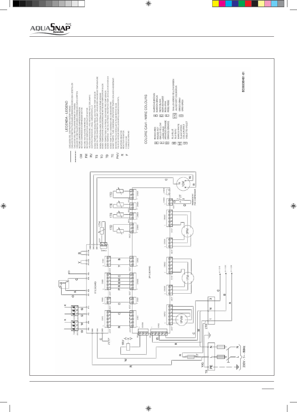
Inverter control size 012NX

                               Electrical connections

4

14-03-2011   14:43:10

50

30AW

GMC control size 012NX

                               Electrical connections

4

14-03-2011   14:43:13

51

30AW

Inverter control size 015HB

14-03-2011   14:43:16

52

30AW

GMC control size 015HB

14-03-2011   14:43:19

53

30AW

Inverter control size 015XB

14-03-2011   14:44:58

54

30AW

GMC control size 015XB

14-03-2011   14:45:01

55

30AW

                               Control management

5

GMC controller

Inverter controller

30AWH012_
30AWH015_

30AWH004_
30AWH006_
30AWH008_

Wired remote (RC1)

Code: 33AW-RC1_

Wired remote (CS1)

Code: 33AW-CS1_

14-03-2011   14:45:03

56

30AW

                               Control management

5

5.1 Introduction

5.2 Unit Control

USER INTERFACES

GMC CONTROL

INVERTER CONTROLLER

Users can select the desired operating

NPEFUISPVHIEJòFSFOUSFNPUFDPOUSPMMFST

Control is based on the GMC platform developed by Carrier. For the 
30AWH AquaSnap PLUS inverter chiller / heat pump a new GMC board 
has been developed as well as new algorithms have been implemented.
The GMC control elaborates the request from the user interface and 
translates it into a message for the chiller unit control. It continuously 
analyzes the water, indoor ambient conditions and the customer 
requests sending updated signals to the chiller unit control.
The chiller unit control takes care of the system reliability and satisfies 

The main flow of logic in this control is as follows: The control reads 
in inputs from discrete inputs, analog inputs, communications. These 
inputs are then processed by mode control. After the mode control 
comes the protections that protect the unit from damage. After the 
protections, the outputs are energized or de-energized. Then the loop 
repeats itself.
High voltage communications is used to communicate from the GMC 

the requests coming from Inverter control tuning chiller unit fan, PMV, 
compressor.
The chiller unit control continuously sends back signals to the Inverter 
control.

board to inverter control.
Maximum values are maximum compressor frequency allowed unless 
limited by a protection or message received from the User Interface.
The User Interface can limit the maximum compressor frequency from 

UP

A2W

Size

Inverter

Capacity

(kW)

GMC Control

returned to Inverter

(HP)

Minimum

Cooling

(Hz)

Maximum

Cooling

(Hz)

Minimum

Heating

(Hz)

Maximum

Heating

(Hz)

4   

4

1,25

20

90

20

95

6

6

1,75

10,2

100

10,2

104

8

8

3

10,2

82

10,2

104

12

12

5

15

65

15

60

15

15

6

10,2

65

10,2

70

14-03-2011   14:45:05

57

30AW

                               Control management

5

When power supply is reset

Fail Mode

Anti Freeze Protection in Off Mode

When a unit is powered up, depending on its Auto Start configuration, it will start up with its last operating parameters, or 
OFF Mode.

The EEPROM is available for saving the operating environment of the control in the event of a power-reset condition. If not 
configured for auto start, at the power up the system will remain in OFF Mode.

All the NUI codes will be restored on a power up condition.

When the unit has a diagnostic failure, fail mode is executed.

*GUIF0QFSBUJOH.PEFJT'"*-UIFOUIFPOCPBSE-&%XJMMCMJOLUIFGBVMUDPEFTFOEUIF'PSDFE0òNFTTBHFUPUIF6OJUJO

case of not recoverable error and Water pump remains energized. In addition and if connected, the same message code 
will be sent to NUI and, as an alternative, the alarm relay output should be activated as defined.

5IJTBMHPSJUINQSPUFDUTUIFSPPNGSPNGSFF[JOHXIFOJO0ò.PEFBOEJGTFMFDUFECZUIF6TFS )0.&"/5*'3&&;&FOBCMFE

that can also select the Antifreeze Temperature. An hysteresis of - 0°C /+2°C should be applied.

AF:

 Anti-

Freeze
NUI Code 2

HOME

ANTIFREEZE

AF

STATUS

CHILLER

UNIT: OFF

WP: OFF after

35 sec. if

was ON

NUI: OFF

Mode: ON Heat

WSP: 35°C

WP: ON

NUI: Display Antifreeze

CHILLER UNIT: OFF

WP: OFF after 30 sec. if

was ON

NUI: OFF + Antifreeze

START

Disable

enable

T< AF Value

T   AF Value

<

14-03-2011   14:45:05

58

30AW

                               Control management

5

Operating mode selection

The operating mode is selected based on the command chosen by the remote control.

Cooling Mode

Depending by the system configuration and when the operating mode is cool, the system could operate as follows:
With Comfort NUI (CS1).
With SUI (RC1) / Dry inputs.
The WSP (Water Set Point) will be defined as follow:

- Fixed WSP: as per the appropriate variable value (Standard and Eco)
- Climatic Curve depending by OAT (see the controls manuals and the paragraph 7.3.5 )

For more information about the cooling mode logics used to determine the WSP, refers to the SUI or NUI manuals.

Heating Mode

Depending by the system configuration and when the operating mode is Heat, the system could operate as follows:
With Confort NUI (CS1).
With SUI (RC!) / Dry inputs

The WSP will be defined as follow:

- Fixed WSP: as per the appropriate variable value (Standard and Eco)
- Climatic Curve depending by OAT (see the controls manuals and the paragraph 7.3.5 )

Off Mode

If the Operating Mode is OFF then:

- All outputs must be de-energized except those turn on by protections.
- Send Forced OFF Message to the unit
- Water pump is de-energized AFTER 30 SEC.
- Antifreeze and all protections algorithms will be always operative
- Sanitary Hot Water management in OFF mode is based on code 153 (1: always active 2: active only in HTG or CLG 

mode)

In case of User Interface is Simple User Interface (dry contacts). The code 100 must be 0 or 1 & code 101 must be 0.

*GUIFWBMVFPGUIFDPEFJTUIFTUBUFPGUIFVOJUJTi$POUSPMMFE0ò$ZDMFw5IJTGFBUVSFJTBWBJMBCMFJO)FBUJOHNPEFJO

Cooling mode and in SHW demand. Every time the compressor turns on a timer restarts to count the Compressor Run 
Time (CRT).

8IFOUIFESZDPOUBDU0òTJHOBMJTSFDFJWFEUIFi$POUSPMMFE0ò$ZDMFwGFBUVSFSFBETUIF$PNQSFTTPS3VO5JNF

- If CRT < 18 minutes the compressor frequency is progressively reduced from the current to the
minimum value until CRT >18 minutes.

*G$35NJOVUFTUIFVOJUJTUVSOFE0ò

OAT: 

Outdoor 

Air
Temperature

WSP: 

Water Set Point

Compressor Frequency Calculation

- When the Frequency reduction mode is activated through the NUI Bus, RS 485 bus or Limitation Frequency Input, the 

max compressor frequency

' O.BYJNVN$PPMJOH)FBU)['3&23&%6$5 UIBUWBMVFDPVMECFTFUCFUXFFOBOE

- When the Unit Mode is OFF, the unit operates in cool/heat satisfied mode with a compressor frequency of zero, F(n) =0.

Calculating Frequency

The calculated water temperature exiting exchanger and calculated set point are continuously monitored. The frequency 
is calculated on the values of LWT and WSP. If the leaving water temperature changes causing a positive delta or if the 
calculated set point changes, a normal demand calculation is performed every 90 seconds (60 in heat mode). Now the 
frequency is calculated on the values of E(n) and  ΔE(n).

Demand vs. Satisfied

8IFOUIFDPNQSFTTPSJTPòBOEEFMUB'UIFDPNQSFTTPSJTBMMPXFEUPTUBSU'NBY 'DNJO' O PSJOIFBUJOH'

max (Fhmin, F(n)) ) , and demand calculations execute every 90 (60 in Heat mode) 

seconds.

8IFOUIFDPNQSFTTPSJTPòTFOE$PPM)FBU4BUJTöFENFTTBHFUPUIFVOJU

- When the compressor is on send the Cool/Heat Demand message to the unit. 

Water pump is always energized

LWT:

 Leaving water

temperature

WSP:

calculated water
set point 

F(n):

 frequency

sent to the
unit, clamped
between zero
and Fcmax

E(n)=

LWT- WSP

Δ

E(n): 

E(n-1)-E(n)

Fcmax:

maximum com-
pressor
speed allowed
in cooling 

Fcmin:

minimum
compressor
speed allowed
in cooling 

Fhmax:

maximum
compressor
speed allowed
in heating

Fhmin:

minimum
compressor
speed allowed
in heating

14-03-2011   14:45:05

59

30AW

                               Control management

5

Dehumidifier activation (X and H terminal block pins 11 – N)

Compressor Short Cycling Protection (Timeguard)

Minimum Compressor Run Time

Water Freeze Protection

External dehumidifier source is based on NUI Relative Humidity value, (For this feature is necessary install 33AW-CS1 
interface).
Two codes shall be accesses through NUI:
Code 108:
It is for defining availability of external dehumidifier.

1 = Alarm or Defrost
2 = External Dehumidifier activation

Code 107:

- It is Relative Humidity Limit value to activate the heat source.
- If Relative Humidity is higher than Humidity Limit, Output PINS 11-N must be forced ON and display dry mode icon on 

NUI.

0VUQVUTIPVMECFGPSDFE0''XIFO3FMBUJWF)VNJEJUZJTMFTTUIBOTFMFDUFEWBMVF

Protections are activated based on operative Mode.

NUI code 108
and 107

'PSSFMJBCJMJUZQVSQPTFTXIFOUIFDPNQSFTTPSHPFTGSPN0OUP0òJUNVTUSFNBJOPòGPSBNJOJNVNPGNJOVUFTBOE

seconds. During that time F(n) = 0, and a Cool Satisfied or Heat Satisfied message is sent to the Unit depending on the 
mode.

5PBWPJETIPSUBOEGSFRVFOUPOPòDZDMFTUIFDPOUSPMBMHPSJUINXJMMBWPJEVOJUUVSOJOHPOVOUJMNJOVUFTIBWFFMBQTFEJG

last on cycle was shorter than 10 minutes. (The maximum number of cycles for hours is six).

8IFOUIFDPNQSFTTPSJTSFBEZUPUVSOPOBSBOEPNEFMBZPGoTFDPOETIPMETUIFDPNQSFTTPSPò

Water Pump remains always ON during Timeguard.

For reliability purposes this algorithm forces the compressor to run for a minimum amount of time.

0ODFUIFDPNQSFTTPSJTSVOOJOHJUNVTUSVOGPSBNJOJNVNPGNJOVUFTCFGPSFTXJUDIJOHPò

This protection is ignored when:

"EJBHOPTUJDGPSDFTUIFDPNQSFTTPSPò
6TFSSFRVFTUTUIFVOJUUPUVSOPò

- A/C Power Interruption
- A mode change occurs
- 20 second loss of high voltage communications
- High temperature protection

When the water starts gets too cold, there is the risk of freezing in the heat exchanger.
Certain actions are taken to prevent freezing.
This protection starts if TR or Tw go down particular values as per conditions below.

While in Zone N or H the frequency can’t increase.
While in Zone M the frequency is forced to decrease until Fcmin.

#FMPX[POF.UVSOPòUIFDPNQSFTTPSBOETFUNPEF0''

Tw:

Min(Actual
Water
Temperature
Entering,
Actual Water
Temperature
Exiting)

Fr(n):

real frequency
from the Unit

Fcmin:

minimum
compressor
speed allowed
in cooling

TR:

Refrigerant
temperature

Compressor OFF 

     4 °C 

  2 °C 

  5 °C 

  Tw 

 -5 °C 

 -7 °C 

 -3 °C 

 TR 

14-03-2011   14:45:06

60

30AW

                               Control management

5

High Temperature Protection

Anti frost protection

A/C Power Interruption

Envelope Limitation Protection

When the water starts to get to hot, this is a sign that the pressure in the system is increasing.
Certain actions are taken to decrease the pressure.

While in Zone N or L the frequency can’t increase.
While in Zone M the frequency is forced to decrease until Fcmin.

*G5XŻPS5Sƥ¡$UIFOUVSOPòUIFDPNQSFTTPSBOETFU'

Tw:

Max(Actual
Water
Temperature
Entering,
Actual Water
Temperature
Exiting)

Tr:

 Actual

Refrigerant
Temperature

Fr(n):

real frequency
from the chiller
unit

Fhmin:

minimum
compressor
speed allowed
in heating

This function shall run when the unit is manually stopped or shutdown due to alarm. It shall protect the water exchanger 
against freezing risk because of low outside temperature conditions.
The following logic shall be used:

EJòFSFOUGBMMEPXOUISFTIPMEMJNJUTIBWFCFFOCFEFöOFEUPTFRVFOUJBMMZQPXFS0O

o Trace Heater (first intervention) (when installed).
o Water Pump (second intervention)

P6OJU0OJO)FBU.PEF BOE5)0ò 

EJòFSFOUSJTFVQUISFTIPMEMJNJUTIBWFCFFOEFöOFEUPTFRVFOUJBMMZ1PXFS0ò

P6OJU0ò BOE5)0O
P8BUFS1VNQ0ò
P5SBDFIFBUFS0ò

DELTA SP: 

NUI CODE 

109

WP:

 Water Pump

TH: 

Trace heater

HP:

 Heat Pump

OAT: 

Outdoor Air 

Temperature

EWT:

 Enter Water

Temperature

LWT:

 Leaving Water

Temperature

This algorithm handles the case of losing A/C line cycles.

*GUIF"$XBWFGPSNJTMPTUGPSNJMMJTFDPOETGPSDFUIFDPNQSFTTPSPòCZTFOEJOH'PSDFE0òTJHOBMUP6OJU5IFOTFOE

 cool satisfied or heat satisfied until time guard expires.

This function limits frequency based on a combination of OAT and LWT, in order to guarantee the unit envelope. The

FOWFMPQFMJNJUTBSFEJòFSFOUGPSIFBUJOHBOEDPPMJOHNPEFBOEDIBOHFGSPNBTJ[FUPBOPUIFS

HEATING
-20 °C ≤OAT≤30 °C
20 °C≤LWT≤60 °C

COOLING
0 °C ≤ OAT ≤ 46 °C
4 °C ≤  LWT ≤ 18 °C

For more details see par 2.4 Operation Limits
When the OAT and/or LWT values are out of these limits the Aquasnap unit doesn’t stop but it works in particular 
conditions in order to preserve the compressor (frequency and for uptime limitation).

OAT:

 Outdoor Air 

Temperature

LWT:

 Leaving Water 

Temperature

TH

WP

HP

Threshold A

[(EWT or LWT < (DELTA SP + 4°C))]

ON

OFF

OFF

Threshold B

[(EWT or LWT < (DELTA SP + 3°C))]

ON

ON

OFF

Threshold C

[(EWT or LWT < (DELTA SP + 2°C )]

OFF

ON

ON

Threshold D

[(EWT and LWT > (DELTA SP + 5°C)] 

OFF

OFF

OFF

 Compressor OFF 

 61 °C 

60 °C 

 62 °C 

  Tw 

14-03-2011   14:45:07

61

30AW

                               Control management

5

Unit Status and Defrost output or Tair Setpoint status

Based on the NUI code 147 set-up, the Output J7 Pin 2 (N-5 on the terminal block) could play for one of these Functions:

- ALARM: The intent of this output is to point out the alarm condition. This signal could be
  used by an external control to verify if the Unit is able to operate with the requested function.
- Tair SETPOINT STATUS: The intent of this output is to give signal to a potential Fan Coil System when the T ambient 

set-up measured by the NUI is reached. A hysteresis of +1°C / –   1°C is used. This signal could be used like a window 
contact by the Fan Coil to stop the fans and/or the water valves.

NUI code 147

Sanitary water Input and 3 Way Valve Output

The combination of the Sanitary Water Inputs and Outputs should be able to manage an external Sanitary Water Boiler 
and this is the logic that is driving this function:

- When an external Sanitary Water Boiler needs hot water from the units, it close   the dry contact Pins 13-15 on the 

terminal block.

- The routing that is always running in order to verify Input changes detect this need and the unit   mode, whichever 

it is the current status, become in HEAT mode at the max allowed WSP   admitted as per the Enveloped Limitation 
protection.

- In case of no alarm or defrost is active, the 3 Way Valve Output (pins N-10-18 on terminal block) become ON while, vice
  versa, this output is always OFF in case of alarm and/or Defrost
- In addition, the NUI, if available, will display the relative Icon.

5IFDPEF 4)8JOPòNPEFEFUFSNJOFTJGUIF4)8-PHJDTIBMMCFBDUJWFPSOPUXIFO4ZTUFN.PEFJT0''*O)FBU

or Cool Mode the SHW logic is always actives.

NOTE: when SHW is ON, EHS is always OFF

SHW: 

Sanitary

Hot Water

EHS:

 External

Heat Source 

WSP:

 water set-point

NUI code 153

Water Pump On / Off Management

The water pump should be always ON apart if any alarms are active or if the unit is in OFF mode (selected or forced by the 
unit itself ).
When the system turn OFF the water pump must be ON for additional 30 seconds.

8IFOUIFVOJUJTTUPQQFEGPSNPSFUIBOIPVSTUIFQVNQTIBMMCFTUBSUFEGPSTFDPOETTUBSUJOHUIFQVNQQFSJPEJDBMMZ

for few seconds increases the life time of the pump.

If OAT < temperature set in code 148
The main water pump activation depending by the code 155 (0. always ON, 1. always OFF or 2. ON/ OFF depending by 
EHS)

SHW: 

Sanitary

Hot Water

EHS: 

External

Heat Source

NUI codes 148,
155

Additional water Pump On / Off Management

The management for the additional water pump, linked to the pin 12 on the X and H terminal block, is the following:

If OAT > temperature set in code 148
The additional water pump activation depending by the code 156

0/0''EFQFOEJOHCZNBJO81MPHJDJODBTFPG4)8BDUJWBUJPO"%%81JT0/
0/0''EFQFOEJOHCZNBJO81MPHJDJODBTFPG4)8BDUJWBUJPO"%%81JT0''

If OAT < temperature set in code 148
The additional water pump activation depending by the code 157 (0. always ON, 1. always OFF or 2. ON/ OFF depending 
by EHS)

SHW: 

Sanitary

Hot Water

EHS: 

External

Heat Source

WP: 

Water

Pump

ADD WP:

Additional
Water Pump

NUI codes 148,
156, 157

Flow Switch Protection

*GXBUFSJTOPUøPXJOHUISPVHIUIFIFBUFYDIBOHFSUIFDPNQSFTTPSDBOOPUUVSOPOBOEJGJUJTPOJUJTGPSDFEPò8BUFS
1VNQXJMMCFGPSDFE0OPS0òBTQFSøPXTXJUDIPVUQVU

- If flow switch contact is open (no water flow) Unit and WP turn OFF.
- The system retries to start for 5 times before displaying alarm.

The compressor is allowed to turn on if requested to when the water is flowing through the heat exchanger (flow switch 
contact OFF) and timeguard has expired.

Settings:
Size 4kW = 300 l/h
Other Sizes = 420 l/h

14-03-2011   14:45:07

62

30AW

                               Control management

5

Backup External Heat Source functionality 

(X and H terminal block pins 5 – N)

This functionality is valid when user mode is HEATING MODE.
Between pins 5 and N of terminal strip (see paragraph 4.1) an output is available (1 ph ~ 230V, 2A max) to activate a 
backup external heat source (such as Electric Heater or Boiler).
This functions is activates using the NUI.
NUI Codes for this function:

106: 1 for External heat source (2 for Defrost Output) 
148: OAT limit for External heat source (-20°C / +65°C)
150: Auxiliary OAT limit. This code is defining the EHS threshold value under witch both HP and EHS will be operative as 

per algorithm. (-20°C / +30°C)

151: Auxiliary Delay. Delay time before switching the back-up EHS ON min. (1 min / 60 min)
152: Auxiliary Hysteresis. Delta T needed to activate the Auxiliary Heater. (1°C / 20°C)
153: SHW in OFF MODE. This code is defining if, when System mode is OFF, the SHW logic can be activated.
154: EHS OUTPUT. This code is defining the EHS output status when EHS is activated and OAT<Code 148
155: Main water pump vs EHS OAT. This code is defining the water pump logic when EHS is activated and OAT<Code 148
156: Additional WP vs SHW (0 Trace heater Output active)
157: Additional WP ( X and H terminal block pins 12 – N)

If code 148 < OAT < code 150:

When LWT is below the water set-point minus the auxiliary hysteresis (code 152) starts the EHS timer (A). When the set delay 
(code 151) is passed (B) the External Heat Source turns ON and the HP is regulated at the max frequency. The EHS turns 
OFF when the LWT reached the water temperature set point (C) (EHS timer is set to 0). The additional water pump will be 
activated depending by main water pump (always ON if main water pump is ON) and by the code 156 (ON or OFF as per SHW 
activation).

If OAT < code 148:

The HP turns OFF (frost protection is active)
The EHS turns ON/OFF depending by setting of the code 154 (Always ON, Based on Room temperature or Water 
Temperature).
The main water pump activation depending by the code 155 (always ON, always OFF or depending by EHS status)
The auxiliary water pump activation depending by the code 157 (always ON, always OFF or depending by EHS status)

NOTE:

*ODBTFPG4)8BDUJWBUJPO QJOTDMPTFEIFBUQVNQXJMMUVSOPOBOECBDLVQIFBUFSXJMMUVSOPò5IJTXJMMIBQQFOJOCPUI

the above strategies based on OAT value.
In case of EHS installation it is mandatory to install a thermal switch on the water circuit to protect the system from too high 
water temperatures. This protection item has to be located Immediately downsteam the EHS (according to local/national 
legislations).

SHW: 

Sanitary Hot 

Water

EHS: 

External Heat 

Source

HP:

 Heat Pump

OAT: 

Outdoor Air

Temperature

WP: 

Water Pump

NUI Codes
106, 148,
150, 151,
152, 153,
154, 155,
156, 157

OAT < T set in CODE 148

A

B

C

Water Temperature Set-point

Indoor Temperature Set Point

ON

OFF

OFF

OFF

OFF

CODE 151

0=Always ON

1=ON/OFF based 
on room T

OFF

ON

OFF

ON

2=ON/OFF based 
on WSP

ON

OFF

ON

OFF

ON

OFF

OFF

0=Always OFF

1=ON/OFF based 
on EHS ON/OFF

2=Always ON

0=Always OFF
1=ON/OFF based 
on EHS ON/OFF

2=Always ON

E 152

 Auxiliary Hyst

HP System mode

OFF

ON

Frost protection

ON

OFF

EHS timer

OFF

ON

AUX Delay

EHS OUTPUT 

CODE 154

ON

OFF

ON

OFF

OFF

OFF

As per standard logic

Depending by EHS ON/OFF

ON

T set in CODE 148 < OAT < T set in CODE 148

ADDITIONAL 

WATER PUMP 

CODE 157

OFF

Depending on main water pump or, when SHW is active,   by 

CODE 156

Depending by EHS ON/OFF

ON

Max Frequency

OFF

OFF

MAIN WATER 

PUMP

     CODE 

155

14-03-2011   14:45:09

63

30AW

                               Control management

5

System Diagnostics

Output test

Pulse Modulating Valve [PMV] control (cooling and heating operation)

The control contains diagnostic tests to verify the integrity of the system.
The On Board LED is located on the circuit board. It is used to display normal operation status and diagnostic fault code 
information.
The control board status LED will flash at a rate of one (1) second ON and one (1) second OFF while the control is operating 
normally.
When in a diagnostic fault code, it will blink out the fault code.
Once a failure occurs, the system is considered failed. The failure could be recoverable or not. The lowest diagnostic number 
that is active will be the fault code that is displayed.

When a diagnostic is active the onboard LED will blink the fault code out. The sequence will be 4 seconds with the onboard 

-&%TPò5IFPOCPBSE-&%XJMMCMJOLBUBSBUFPGIBMGTFDPOEPOIBMGTFDPOEPòGPSFBDIOVNCFSJOUIFUFOTEJHJU5IFO
TFDPOETPò5IFPOCPBSE-&%XJMMCMJOLBUBSBUFPGIBMGTFDPOEPOIBMGTFDPOEPòGPSFBDIOVNCFSJOUIFPOFTEJHJU*GUIF

fault code is less than 10 the delay will be 6 seconds between onboard LED flash sequences.
Fault Codes associated with diagnostic will be available through communications.
Fault code 14 and 8 shall be give top priority and shall by pass other fault codes. Fault codes priority order shall be the same 
as in the given below table in absence of Fault codes 14 and 8.

SUI Alarm:

When any diagnostic is active and in case SUI is connected, SUI Alarm LED shall blink as just the same way as Onboard LED. In 
absence of diagnostics SUI Alarm LED shall remain OFF.

Fault codes on NUI:

Main Board shall communicate the diagnostic with NUI. User or Installer can view these fault codes through an entry into 
User settings mode or Installer settings Mode and scroll to the fault code as mentioned in the Variable table. NUI shall scroll all 
the active fault codes. In absence of diagnostics, NUI shall display blank. NUI shall also manage to store the latest 4 fault codes 
and Installer can view this value by scrolling to Fault code History parameter.
For more information about the fault code on controls NUI and/or SUI refer to their specific manuals.
For specification of fault code refer to the specific paragraph:

i(.$BMBSNDPEFTw

Recoverable:

self healing
diagnostic

Not
Recoverable:

Must cycle
power up to the
unit to fix the
system.

This test will be used by the Installer to test and/or to force ON the outputs, setting the code 104 on the NUI:

NUI Code 104

0. No test
1. Water pump
2. Alarm / Ambient temperature reached
3. External Heat Source / Defrost

4. Alarm + defrost / Humidity
5. Trace Heater / Additional Water Pump
6. 3 Way Valve
7. SUI Alarm
8. N.A.

5PQFSGPSNBOZPVUQVUUFTUUIF6OJUNVTUCFJO0ò JGOPU0òNVTUCFGPSDFE"GUFSNJOVUFTUIFVOJUBVUPNBUJDBMMZFYJU
GSPNPVUQVUUFTU5PQFSGPSNBOZPVUQVUUFTUUIF6OJUNVTUCFJO0ò JGOPU0òNVTUCFGPSDFE

Pulse Modulation Valve is a refrigerant bi-flow electronic expansion device driven by a stepper motor.
It’s use to optimize refrigerant superheating and avoid refrigerant liquid back into the compressor. 
1) The PMV is controlled with 50 to 500 pulses during the operation, respectively.

5IF1.7JTDPOUSPMMFEVTJOHUIFUFNQFSBUVSFEJòFSFODFCFUXFFO

54TFOTPSBOE53TFOTPSJODPPMJOHNPEF54TFOTPSBOE5&TFOTPSJOIFBUJOHNPEF5IFUBSHFUJTUPNBJOUBJOUIF
UFNQFSBUVSFEJòFSFODFGSPNUP,

3) During max loading conditions, the refrigerant circuit pressures & temperatures can increase excessively, so the PMV is
     controlled by the TD sensor.

TS:

 Suction

temperature

TR:

Refrigerant
temperature

TE:

 Entering

(in Heat
exchanger)
temperature

14-03-2011   14:45:10

64

30AW

                               Control management

5

Discharge temperature release control

Current release control

1) This function controls the compressor frequency, when the discharge temperature has increased due to max load 
condition or during PMV control. It subdivides the frequency control up to a unit of 0.6 Hz to stabilize the cycle. 
2) When the discharge temperature is detected in an abnormal stop zone, the unit stops the compressor and restarts it after 
2 minutes, 30 seconds (time guard). The error count is cleared when operation of 10 minutes without error occurs. If the 
abnormal stop zone has been detected 4 times without clearing, an error code is displayed.
* Possible causes include excessive amount of refrigerant, defective PMV, or blockage in the refrigeration cycle.

a

b

c

d

e

30AWH004

117

112

108

105

98

30AWH006

117

112

108

105

98

30AWH008

117

107

103

100

93

30AWH012

111

106

100

95

90

30AWH015

111

109

106

103

96

TD: 

Discharge

temperature

The output frequency and the output voltage are controlled by AC current detected on the P.C. board.
The max current value of the inverter are shown in table below.

Frequency down

Frequency holding

Frequency slow-up
(Based on command)

As command

Error stop ("P03" displayed after 4 error counts)

a

b

c

d

e

TD[

o

C]

Frequency down

Hold

Hold

Normal operation

[A]

l1 value [A]

COOL

HEAT

30AWH004

6.3

6.3

30AWH006

8.5

10.8

30AWH008

10.1

12

30AWH012

23

23

30AWH015

20

20

14-03-2011   14:45:11


Content      ..     2      3      4      5     ..