UD Trucks. Owner’s Manual (2011-2013) - page 7


  Главная      Manuals     UD Trucks. Owner’s Manual (VEHICLE SERVICE AND MAINTENANCE) (2011-2013)


Search            copyright infringement  


Content      ..     5      6      7      8     ..


UD Trucks. Owner’s Manual (2011-2013) - page 7


-------------------------------------------------------------------------------------------------------------------------------------------------------------
INSTRUMENTS AND CONTROLS
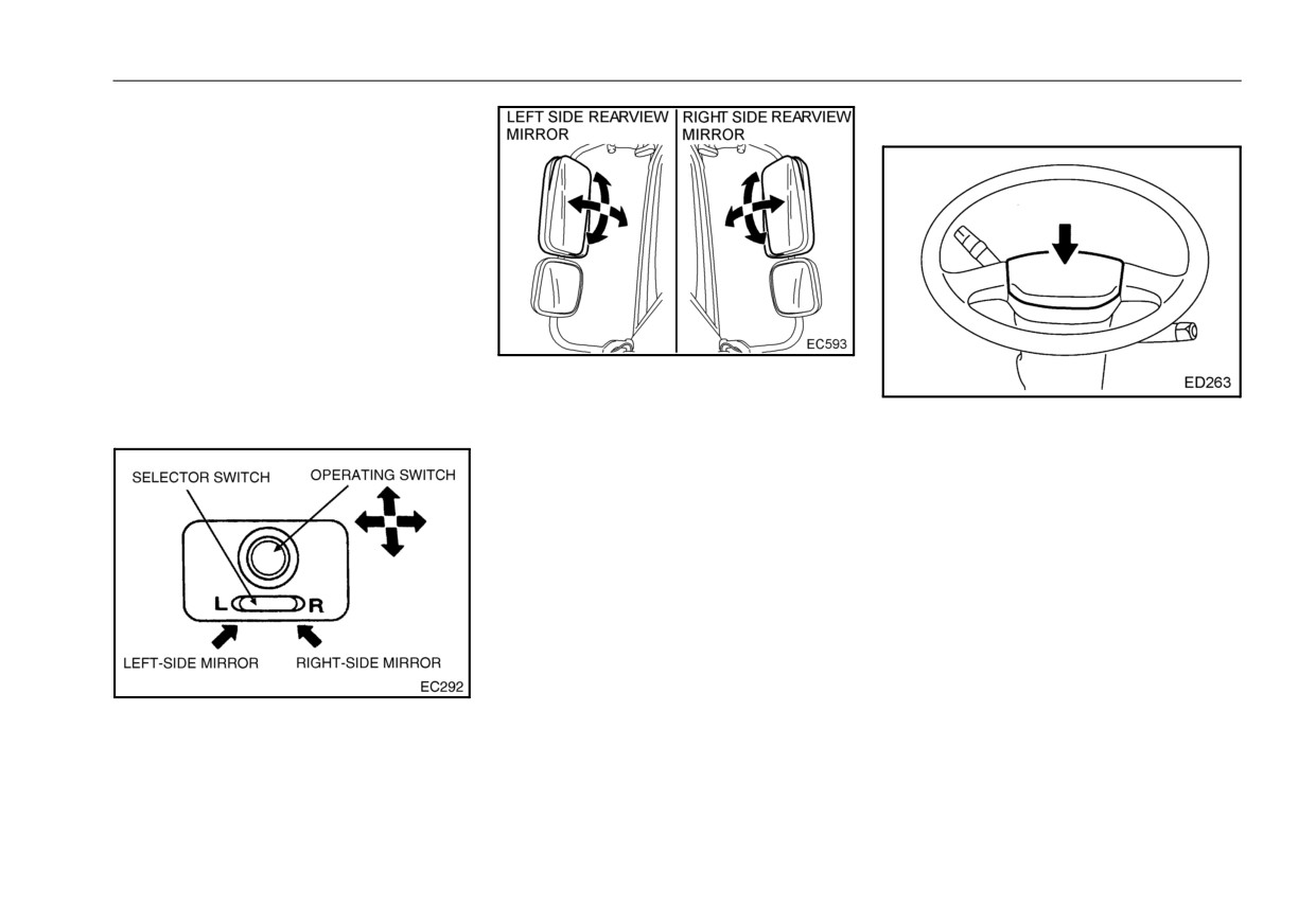
Power mirror switch (Optional)
Horn
This switch is located on the instru-
ment panel below the heater control.
This switch is used to adjust the
angle of the rear view mirrors on the
driver’s side and passenger side. It
will operate when the ignition key is
turned to the ON position.
z Push the right/left selection switch
and then move the operation
switch up or down, left or right to
adjust the view to the rear.
The horn pad is mounted in the cen-
ter of the steering wheel. Press on
the pad to sound the horn.
7 - 68

-------------------------------------------------------------------------------------------------------------------------------------------------------------

INSTRUMENTS AND CONTROLS
DPF SYSTEM
NOTE:
z
If a certain amount of soot from
z
The PM reduction device collects
exhaust gas accumulates in the
the soot (particulate matter) that is
DPF, the PM reduction device
part of exhaust gas through the
automatically burns
(regener-
aftertreatment diesel particulate fil-
ates) the collected soot.
Depending on the driving condi-
ter
(DPF) located in the muffler,
tion, soot may not be com-
and then continuously regenerates
pletely burned (regenerated). In
(burns) the soot by oxidation catal-
that case, the DPF clogging
ysis.
warning light and the indicator
z
When continuous DPF regenera-
light that is built in the manual
tion cannot be performed due to
forced regeneration switch will
low speed driving, the automatic
flash to indicate that manual
DPF regeneration starts to burn
DPF regeneration is needed.
(regenerate) the soot to prevent
excessive accumulation in the
DPF that is located inside the muf-
fler.
z
When automatic regeneration
does not operate due to low speed
driving or starting/stopping the
engine many times while driving,
manual regeneration must be per-
formed after stopping the vehicle.
z
Based on the amount of soot accu-
mulated in the DPF, perform DPF
regeneration following the table
below.
7 - 69

-------------------------------------------------------------------------------------------------------------------------------------------------------------

INSTRUMENTS AND CONTROLS
Soot deposit
Status of the vehicle
Cleaning method
accumulation
Little
(Continuous regeneration is performed while driving at a high
Normal driving
speed or with a high load, therefore, soot is burned and
cleaned.)
When a certain amount of soot is accumulated, the soot is
Automatic DPF regeneration
automatically burned and cleaned.
Flashing of the DPF clogging warning light
Stop the vehicle in a safe location, and then perform manual
and the indicator light that is built in the
DPF regeneration.
manual forced regeneration switch
DPF system warning (Amber) and warning
Contact your nearest UD Trucks dealer for inspection.
message are displayed
Large
Device information
DPF clogging warning light
z The DPF clogging warning light
Manual forced regeneration switch
will blink if manual DPF regenara-
tion should be performed due to
soot accumulation in the DPF.
When the warning light blinks, per-
form the following procedure.
z Also, when the ignition key is
turned to the ON position, it illumi-
nates for
1 second for a bulb
check.
Procedure
Stop the vehicle in a safe location,
and then perform manual DPF
7 - 70

-------------------------------------------------------------------------------------------------------------------------------------------------------------

INSTRUMENTS AND CONTROLS
regeneration by operating the man-
DPF soot level gauge
ual forced regeneration switch.
z
The DPF soot level gauge indi-
WARNING
cates the accumulation level of the
z
Immediately after the vehicle is
Manual forced regeneration switch
soot in the DPF. Check if neces-
stopped or while the system is
z
By operating this switch, the soot
sary.
in the cleaning mode, the area
collected in the DPF is manually
z
For details on how to display, refer
around the muffler and
burned (regenerated) to keep the
to the “Multi-display monitor” sec-
exhaust gas are extremely hot.
function of the exhaust gas clean-
tion in “INSTRUMENT AND CON-
Do not stop the vehicle in a
ing device properly.
location where there are flam-
TROLS”.
For details on how to use this
mable materials such as dried
switch, refer to the “Manual DPF
grass or paper waste.
regeneration operation” section.
z
If there are flammable materi-
z
The indicator light that is built in
als around the vehicle, a fire
may occur. This could cause
the switch will blink just as the DPF
burns from the heated exhaust
clogging warning light blinks if
gas.
manual cleaning should be per-
formed due to soot accumulation
in the DPF.
NOTE:
z While performing automatic
regeneration, engine noise will
vary and engine speed at idle
Automatic DPF regeneration
will increase. This does not indi-
z To prevent excessive accumula-
cate a malfunction.
tion of soot in the DPF, the soot is
automatically burned and cleaned.
Though engine noise and engine
speed at idle will vary, the vehicle
can be driven as usual.
7 - 71

-------------------------------------------------------------------------------------------------------------------------------------------------------------

INSTRUMENTS AND CONTROLS
Manual regeneration (when the
z The approximate time required for
NOTE:
DPF clogging warning light
manual
DPF regeneration
z If the vehicle is driven under any
blinks)
of the following conditions, the
depends on the conditions the last
DPF clogging warning light may
time the vehicle was driven and
z If the vehicle is driven at a low
blink many times because the
the engine idling status, however
speed or the engine is started/
automatic regeneration may not
normally it takes 25 minutes.
stopped many times while driving,
operate.
the soot in the DPF may not be
The vehicle is frequently driven
1.Stop the vehicle in a safe location,
burned and cleaned automatically.
at a low speed.
and then keep the engine idling.
z In this case, the DPF clogging
The engine is started/stopped
2.Be sure to apply the parking brake.
warning light informs the driver
many times while driving.
Place the gearshift lever in the
that the soot in the DPF must be
The vehicle is driven many
neutral position. Do not depress
burned and cleaned manually.
times for only a short distance.
the accelerator pedal.
The engine is always stopped
3.Press the ON side of the manual
before it warms up.
CAUTION
forced regeneration switch.
4.When the DPF regeneration starts,
z When the DPF clogging warn-
Manual DPF regeneration
the warning of DPF regeneration
ing light blinks, operate the
operation
appears on the multi-display moni-
manual forced DPF regenera-
z When the DPF clogging warning
tor. The engine speed at idle will
tion switch to perform the
cleaning manually, and then
light blinks, perform manual DPF
increase.
burn and clean the soot in the
regeneration according to the fol-
DPF.
lowing procedure, and then burn
If driving is continued, clog-
and clean the soot in the DPF.
ging in the DPF or a system
Note that manual regeneration can
malfunction may occur.
be performed when the indicator
light blinks or automatic DPF
regeneration is started.
7 - 72

-------------------------------------------------------------------------------------------------------------------------------------------------------------

INSTRUMENTS AND CONTROLS
device appears
on
the
multi-dis-
WARNING
play monitor.
z
Do not perform manual DPF
regeneration in a location with
poor ventilation. Exhaust gas
may cause carbon monoxide
poisoning especially in an
enclosed location, such as in a
garage, indoors, etc.
z
Do not perform manual DPF
regeneration in a location
where there are flammable
5.When the warning of DPF regener-
materials such as dried grass
ation by the exhaust gas cleaning
or paper waste. The tempera-
device is no longer displayed on
ture of the exhaust gas and the
the multi-display monitor, manual
area around the exhaust pipe
DPF regeneration is completed.
and muffler become high dur-
The engine speed at idle will return
ing the cleaning mode. There-
to normal.
fore, if there are flammable
6.After manual regeneration is com-
materials nearby, a fire may
pleted, the vehicle can be driven
occur.
as usual.
In addition, never allow your
body to contact the exhaust
7.To stop manual regeneration part-
gas and the area around the
way, press the CANCEL side of
exhaust pipe and muffler.
the manual forced DPF regenera-
Doing so may cause burn inju-
tion switch. When manual DPF
ries. If the vehicle is stopped
regeneration is stopped partway,
over a road surface that is
the warning of regeneration restric-
painted, the road surface may
tion of the exhaust gas cleaning
be discolored.
7 - 73

-------------------------------------------------------------------------------------------------------------------------------------------------------------

INSTRUMENTS AND CONTROLS
the engine depends on the out-
partway, it is not completed.
NOTE:
side temperature, but generally
Resume manual regeneration
z
The engine speed at idle
it takes about 5 to 10 minutes.
soon.
increases while manual DPF
Therefore, manual DPF regener-
z If the vehicle is driven before the
regeneration is being per-
ation should be performed
regeneration is completed, the
formed. This is due to a temper-
immediately after the vehicle is
DPF clogging warning light will
ature increase of the exhaust
stopped (while the engine is still
blink again.
gas to burn (regenerate) the col-
warm).
z Manual DPF regeneration can be
lected soot. This does not indi-
z Manual cleaning cannot be per-
performed as stated above even
cate a malfunction.
formed under the following con-
if automatic cleaning is being
z
While performing manual DPF
ditions.
performed.
regeneration, the aftertreatment
The engine coolant
hydrocarbon doser system sup-
temperature (ECT) is low.
When the DPF system warning is
ports the manual DPF regenera-
(Perform after the engine warms
displayed
tion by automatically injecting
up.)
fuel in the exhaust pipe.
z
If the soot accumulation level
z
If the temperature of the inside
The accelerator pedal (AP) is
reaches a specified limit by driving
of the muffler is higher, the man-
depressed.
the vehicle with the DPF clogging
ual DPF regeneration is com-
The parking brake is released.
warning light blinking, the DPF
pleted in a shorter time.
The transmission gear is
system warning, warning message
z
Manual DPF regeneration is
placed in any position other
and comment are displayed on the
completed in a shorter time
than the neutral position.
when the engine is hot immedi-
z For the models equipped with
multi-display monitor to alert the
ately after the vehicle is stopped
the PTO switch, be sure to turn
driver. The warning appears in two
than when the engine is cool.
the PTO switch off when turning
different steps, amber and red.
When the engine is cool, the
the manual forced aftertreat-
z
When it appears, clogging in the
time required for DPF regenera-
ment DPF regeneration switch
DPF or system malfunction may
tion takes longer because the
on. The regeneration process
occur.
DPF regeneration is performed
does not start.
after the engine warms up.
z When manual aftertreatment
The time spent for warming up
DPF regeneration is stopped
7 - 74

-------------------------------------------------------------------------------------------------------------------------------------------------------------

INSTRUMENTS AND CONTROLS
LEVERS AND CONTROL
CAUTION
Transmission gear shift lever
z If the vehicle is continued to be
driven, the engine shutdown
will operate.
z Do not drive the vehicle with
the DPF system warning dis-
played. The DPF that is
equipped with muffler may be
damaged.
NOTE:
z When the amber DPF system
z If the DPF system warning
warning appears, contact your
appears, the exhaust gas clean-
nearest UD Trucks dealer for
ing device may be damaged.
inspection.
Manual DPF regeneration is not The transmission gear shift lever is
z While the amber DPF system
possible.
located on the right of the driver’s
warning appears, engine torque is
seat. When shifting gears, depress
reduced to protect the DPF.
the clutch pedal fully and move the
z When the red DPF system warning
lever firmly. When the shift lever is
appears, immediately stop the
moved into reverse, the backup
vehicle in a safe location and con-
lights come on and the backup
tact your nearest UD Trucks
buzzer sounds. The backup lights
and buzzer are located on the rear of
dealer.
the vehicle.
7 - 75

-------------------------------------------------------------------------------------------------------------------------------------------------------------

INSTRUMENTS AND CONTROLS
Automatic transmission selector
When the selector lever (switch) is
Parking brake valve
lever (switch)
moved (pushed) into R (Reverse)
position, the backup lights come on
and the backup buzzer sounds and
the back buzzer sounds in the cabin.
The backup lights and buzzer are
located on the rear of the vehicle.
The engine starts in the N (Neutral)
or P (Park) position.
Allison 1000, 2200 and 2500 series
The parking brake valve is located to
the rear of the gear shift lever. Pull
the knob up to operate the parking
brake. When the knob is pulled up,
the PARKING BRAKE warning light
comes on. To release the parking
brake, press the knob down. The
warning light will go out.
Allison 3000 series
The selector lever (switch) is located
on the right of the driver’s seat.
7 - 76

-------------------------------------------------------------------------------------------------------------------------------------------------------------

INSTRUMENTS AND CONTROLS
z When parking on a grade,
apply chocks to the wheels in
addition to using the parking
brake.
CAUTION
z
Release the parking brake
before driving the vehicle. Fail-
ure to release the parking
brake
can
cause
brake
dam-
age.
WARNING
z
Never apply the parking brake
when the vehicle is moving.
Such application will lock the
rear wheels and may result in
loss of vehicle control, could
cause damage to the driveline
and/or brake drum on the
transmission.
z
Do not operate the parking
brake valve with a person near
the rear axle. The movement of
the parking brake actuating
rod can cause serious injury.
7 - 77

-------------------------------------------------------------------------------------------------------------------------------------------------------------

ACCESSORIES
Cigarette lighter
ACCESSORIES
CAUTION
z
To avoid damage to the lighter,
do not hold the lighter in man-
ually.
z
Avoid deforming the cigarette
lighter. Using a deformed
lighter could be dangerous, as
it will not pop out. Make sure
that defective parts are
replaced with genuine parts or
equivalent.
z
If the cigarette lighter does not
The cigarette lighter is located at the
pop out within
20 seconds
right side of the heater control. To
after it has been pushed in,
operate the lighter, push it in. The
remove it immediately and
lighter will pop out to its normal posi-
have it checked at an autho-
tion when heated.
rized UD Trucks dealer or other
qualified service facility.
z
Never leave your vehicle with
the cigarette lighter pushed in.
8 - 1

-------------------------------------------------------------------------------------------------------------------------------------------------------------

ACCESSORIES
Power socket
Ashtray
CAUTION
z Do not use a TV while driving.
The use of a TV may shorten
the life of the battery depend-
ing on operating or use condi-
tions. Keep the use of a TV to a
minimum when ever possible.
WARNING
z
The use of any device with a
The power socket is located at the
The ashtray is located inside of the
right side of the cigarette lighter.
higher current than the allow-
right and left doors.
Use the power socket in the cab to
able load can heat the socket
To open the ashtray, pull the tab
connect commercially available car
and cord and cause fire. Use
upward.
accessories. Remove the cap before
devices with the allowable load
To remove the ashtray for cleaning,
use. The following devices can be
current.
pull the tray upward.
connected to the socket.
z
The socket is for 12 volts only.
Do not use any car accessory
for 24 volts with the socket. A
WARNING
Device
Rated current
trouble may be caused in the
Charger for mobile
z To prevent fire, ensure that any
2A
device.
phone
lit or smoldering materials in
z
The socket can be used while
GPS
2A
the ignition key switch is in the
the ashtray are completely
ACC position. Before leaving
extinguished.
TV
9.5A
the vehicle, disconnect the
Wireless device
2.2A
device from the socket.
Computer
7A
8 - 2

-------------------------------------------------------------------------------------------------------------------------------------------------------------

ACCESSORIES
Overhead box
Cup holder
z Be sure to keep the overhead
box closed while driving.
Driving with it open could
allow the items in the box to
fall over and hinder driving.
Store only lightweight items, such as
This is used to hold bottle and cup
the vehicle inspection certificate and
for drinks, etc.
magazines, in the large box with the
lid.
CAUTION
z Avoid abrupt starting and brak-
CAUTION
ing to prevent a drink from
The standard weight of objects
being spilt when it is stored in
stored in the overhead is indi-
the cup holder.
cated below. Storing objects
with the weight exceeding the
following limit may damage the
console and lid.
z Overhead box: 6.6 Ib (3 kg) or
less
8 - 3

-------------------------------------------------------------------------------------------------------------------------------------------------------------

ACCESSORIES
Room light
Card holder
Room light switch
State of the doors
position
Driver’s
Passen-
ON
OFF
DOOR
side
ger side
Turn
Close
off
Open
Close
Turn
Turn
on
off
Turn
Close
Open
on
Open
z
Turning on the room light switch
This can be used to hold such cards
as telephone cards and highway
to ON turns on the room light
cards.
regardless of whether or not a
door is open or closed.
z
The room light turns off when
CAUTION
the room light switch is turned
z To prevent theft, do not leave
to OFF.
credit cards in the card holder
z
When the room light switch is in
when away from the vehicle.
the DOOR position, the room
light will turn on when the
driver’s seat door or the pas-
senger seat door is opened,
and will turn off when the door is
closed.
8 - 4

-------------------------------------------------------------------------------------------------------------------------------------------------------------

ACCESSORIES
Door pocket
Console box (optional)
Door pockets are located in the left
When the seatback of the center
and right doors. Place road maps,
seat is folded forward, some docu-
magazines, etc. inside it.
ments, small items, etc. can be
stored on the reverse side of the
seatback.
8 - 5

-------------------------------------------------------------------------------------------------------------------------------------------------------------

-------------------------------------------------------------------------------------------------------------------------------------------------------------

HEATER OR AIR CONDITIONER CONTROL
AIR CONDITIONER
Air vent
z Use the air conditioner when the
engine is running.
z The engine coolant is used to heat
the air used for heating. The air
coming from the air vent will not be
warm until the engine coolant tem-
perature.
<Handling the blower motor filters>
become clogged, so inspect and
z Both the outside and inside air
clean them periodically.
intakes have a cartridge air filter.
z For information about how to clean
The air conditioner will not be as
the air filter, refer to "BLOWER
effective if these air filters
MOTOR FILTERS" on page 11-82.
9 - 1

-------------------------------------------------------------------------------------------------------------------------------------------------------------

HEATER OR AIR CONDITIONER CONTROL
Manual air conditioner
Change the switch and dial selections to match the season to make your driving pleasant.
Operation Panel
9 - 2

-------------------------------------------------------------------------------------------------------------------------------------------------------------

HEATER OR AIR CONDITIONER CONTROL
Name
Position
Purpose and Function
To stop fan operation:
z This stops the air from the fan and the compressor. However, the fan continues
OFF
operating at the minimum air level when the mode dial is in the “Defrost” posi-
Fan dial
tion.
To adjust the fan speed: The fan speed is adjusted manually.
- HI
z Turn right: Increases airflow, Turn left: Reduces airflow
Use maximum cooling:
COLD
Blows a cool air without passing the air through the heater core.
HOT
Use maximum heating: Blows a warm air after passing the air through the heater core.
Temperature
control dial
Adjust the temperature of the air:
COLD - HOT
This changes the temperature of the air to match the temperature control dial setting.
z Turn right: Increases temperature, Turn left: Lowers temperature
Dial
Vent
Send air from the vent: Set the air outlet to the Vent position.
Vent & Foot
Send air from the vent and foot vents: Set the air outlet to the Vent & Foot position.
Foot
Send air from the foot vents: Set the air outlet to the Foot position.
Send air from the foot and defrost vents: Set the air vents to the Foot & Defrost posi-
Foot & Defrost 1
tion.
Mode dial
Send air from the foot and defrost vents:
Foot & Defrost 2
Set the air vents to the Foot & Defrost position.
(This divides the air to blow more from the defrost vents than from the foot vents.)
Send air from the defrost vents:Set the air vents to the Defrost position.
Set the intake vents to outside air.
Defrost
Run the compressor.
z The minimum air will blow even if the fan dial is set to OFF.
9 - 3

-------------------------------------------------------------------------------------------------------------------------------------------------------------

HEATER OR AIR CONDITIONER CONTROL
Name
Position
Purpose and Function
This switches between the dehumidifier mode (light on) and heater mode (light off).
The light turns on/
Air conditioner
off each time this
z Light on: Compressor is operating normally
switch
is pushed.
z Light off: Heater is operating (compressor is not operating)
Switch
Alternates
between turning
It switches between insider air recirculation and letting in the outside air.
Fresh/Recircula-
on the inside air
z Inside air light: Set to inside air recirculation.
tion switch
light and outside
air light each time
z Outside air light: Set to let in the outside air.
this is pushed.
NOTE:
z Do not operate the dials or switches while driving.
9 - 4


Content      ..     5      6      7      8     ..